

Page 1

BARCOPROJECTION
BARCOELM R18
R9001990
OWNERS MANUAL
17092002 R5976333/02
Page 2

Barco nv Events
Noordlaan 5, B-8520 Kuurne
Phone: +32 56.36.89.70
Fax: +32 56.36.88.24
E-mail: events@barco.com
Visit us at the web: www.barco.com
Printed in B elgium
Page 3

Changes
Barco provides this manual “as is” without warranty of any kind, either expressed or implied, including but not limited to the implied warranties or merchantability andfitnessfora particular purpose. Barcomay make improvements and/or changes to the product(s) and/or the
program(s) described in this publication at any time without notice.
This publication could c ontain technical inaccuracies or typographical errors. Changes are periodically made to the information in this
publication; these changes are incorporated in new editions of this publication.
Copyright ©
All rights reserved. No p art of this document may be copied, reproduced or translated. It s hall not other
stored in a r etrieval system without the prior written consent of BARCO.
wise be recorded, transmitted or
Trademarks
Brand and product name s mentioned in this manual m ay be trademarks, registered trademarks or copyrights of their respective holders.
All brand and produc t names mentioned in this manual serve as com men ts or examples and are not to be understood as advertising for
the products or their manufactures.
Page 4

Page 5

Table of contents
TABLE OF CONTENTS
1. Safety Instructions........ ................ ................ ................ ................ ................ .......... 5
1.1 Warnings ................................................................................................................................ 5
1.2 FCC statement .......................................................................................................................... 5
1.3 Note ..................................................................................................................................... 5
2. Packaging and Dimensions ....................................................................................... 7
2.1 Box Content ............................................................................................................................. 7
2.2 Lens Packaging ......................................................................................................................... 7
2.3 Projector Case .......................................................................................................................... 7
3. Installation Guidelines........ ................ ................ ................ ................ .............. ........ 9
3.1 General.................................................................................................................................. 9
3.2 Configuration...........................................................................................................................10
3.3 Warning on Rotating the Projector ....................................................................................................14
3.4 Safety Area around ProjectorSafety Area.............................................................................................15
3.5 Installation of the Lamp Casing ........................................................................................................15
3.6 Transporting the projector .............................................................................................................17
3.7 Re-adjusting the lamp position in the lamp casing.................................................................................... 17
3.8 Lenses. .................................................................................................................................18
3.8.1 Lenses...........................................................................................................................18
3.8.2 Lens selection ...................................................................................................................19
3.8.3 Lens Formulas................................................................................................................... 19
3.8.4 Lens Installation ................................................................................................................. 19
3.8.5 Cleaning the lens................................................................................................................20
3.9 Battery Installation in the RCU ........................................................................................................20
3.10StackingTwo Projectors...............................................................................................................21
3.11Rigging points and Accessories.......................................................................................................22
4. Connections.... ................ ................ ................ ................ ................ ................ .....25
4.1 Power connection......................................................................................................................25
4.2 Switching on............................................................................................................................25
4.3 Switching to standby...................................................................................................................26
4.4 Switching off............................................................................................................................27
4.5 Input Sour ce Connections ............................................................................................................. 27
4.5.1 Input Facilities ................................................................................................................... 27
4.5.2 Inputs via RCVDS05 ............................................................................................................27
4.5.3 Input module insertion...........................................................................................................27
4.5.4 Fixed slot (slot 1 & 2)............................................................................................................28
4.5.5 Serial Digital Input ( slot 3 & 4) ..................................................................................................30
4.5.6 HD SDI Digital input (slot 3 & 4) ................................................................................................ 30
4.5.7 Digital Video Decoder Input ... .................................................................................................. 31
4.6 Communic ation Connections..........................................................................................................32
4.6.1 RS232 (RS422) Connection .................................................................................................... 32
4.6.2 Communication with peripherals................................................................................................ 32
4.6.3 Network connection ............................................................................................................. 33
5. GettingStarted......................................................................................................35
5.1 RCU & Local keypad...................................................................................................................35
5.2 Terminology overview .................................................................................................................. 35
5.3 Operating the projector ................................................................................................................36
5.3.1 Switching on.....................................................................................................................36
5.3.2 Switching to standby ............................................................................................................37
5.3.3 Switching off.....................................................................................................................37
5.3.4 Temperature error DMD......................................................................................................... 37
5.4 Quick Set up Adjustment .............................................................................................................. 38
5.4.1 Quick Language Change........................................................................................................38
5.4.2 Quick Lens Adjustment..........................................................................................................38
5.4.3 Quick On Screen Color change................................................................................................. 39
5.5 Using the RCU ......................................................................................................................... 40
5.6 Projector Address......................................................................................................................42
5.6.1 Controlling the projector......................................................................................................... 42
5.6.2 Displaying and Programming addresses .......................................................................................43
6. Start up of theAdjustment mode................................................................................45
6.1 Start up.................................................................................................................................45
6.2 Password............................................................................................................................... 45
6.3 Menus on Local LCD Display..........................................................................................................46
7. Random Access Adjustment Mode .............................................................................47
7.1 Overview Flow ......................................................................................................................... 47
7.2 Picture Services........................................................................................................................48
7.2.1 File annotation...................................................................................................................48
7.2.2 Possible filemanipulations......................................................................................................48
R5976333 BARCOELM R18 17092002
1
Page 6

Table of contents
7.2.3 Start up ..........................................................................................................................49
7.2.4 Load file. .........................................................................................................................49
7.2.5 Edit File..........................................................................................................................50
7.2.5.1 Start up....................................................................................................................50
7.2.5.2 Changing the settings ....................................................................................................51
7.2.5.3 Correct value..............................................................................................................51
7.2.6 Rename.. ........................................................................................................................54
7.2.7 Copy .............................................................................................................................55
7.2.8 Delete............................................................................................................................ 55
7.2.9 File Options...................................................................................................................... 56
7.3 Picture Tuning.......................................................................................................................... 56
7.3.1 Start up ..........................................................................................................................57
7.3.2 Color Temperature...............................................................................................................57
7.3.3 Gamma ..........................................................................................................................58
7.3.4 Decoding.........................................................................................................................58
7.3.5 Dynamic Color Depth ...........................................................................................................58
7.3.6 Noise Reduction................................................................................................................. 59
7.3.7 Input Balance.................................................................................................................... 59
7.3.7.1 Input Balance for RGB input signals .. ...................................................................................60
7.3.7.2 Input Balance for YUV signals ...........................................................................................61
7.4 Geometry............................................................................................................................... 61
7.4.1 Introduction ......................................................................................................................61
7.4.2 Geometry start up ............................................................................................................... 62
7.4.3 Shift ..............................................................................................................................62
7.4.4 Size ..............................................................................................................................63
7.4.5 Side Keystone................................................................................................................... 64
7.4.6 Blanking.......................................................................................................................... 64
7.4.7 Aspect Ratio .....................................................................................................................65
7.5 ScenergiX ..............................................................................................................................66
7.5.1 Order information................................................................................................................66
7.5.2 Introduction ......................................................................................................................66
7.5.3 Preparations ..................................................................................................................... 67
7.5.4 Scenergix........................................................................................................................67
7.5.5 ScenergiX overlap zo ne (horizontal scenergix) ................................................................................68
7.5.6 ScenergiX overlap zo ne (vertical scenergix) ...................................................................................69
7.5.7 ScenergiX size adjustment......................................................................................................69
7.5.8 Adjusting the black level of the images......................................................................................... 71
7.6 Picture in Picture (PiP)................................................................................................................. 72
7.6.1 Introduction to PiP............................................................................................................... 72
7.6.2 Picture in Picture activation.....................................................................................................73
7.6.3 Picture in Picture source ........................................................................................................74
7.6.4 Position of Picture in Picture window ...........................................................................................74
7.6.5 Set upof the Quick Selection...................................................................................................74
8. Installation Mode ........ ................ ................ ................ ................ ................ ...........75
8.1 Start up of the Installation mode.......................................................................................................75
8.2 Input Slots ..............................................................................................................................75
8.3 800 peripheral..........................................................................................................................77
8.3.1 Definingthe output m odule of the RCVDS05...................................................................................77
8.3.2 Defining the Infrared Communication protocol ................................................................................. 77
8.4 Source Switching....................................................................................................................... 78
8.5 No Signal...............................................................................................................................78
8.5.1 Changing the Background Color................................................................................................79
8.5.2 Changing the Sh utdown Setting ................................................................................................79
8.5.3 Changing the Shutdown Time ..................................................................................................79
8.6 Contrast Enhanc ement ................................................................................................................80
8.7 Convergence ... ........................................................................................................................80
8.8 Configuration...........................................................................................................................81
8.9 Lens Adjustment ....................................................................................................................... 81
8.10Quick Access Keys.................................................................................................................... 83
8.11OSD ....................................................................................................................................84
8.11.1Color Settings ...................................................................................................................84
8.11.2Menu Position...................................................................................................................85
8.12Internal Patterns .......................................................................................................................85
9. Service Mode..... ................ ................ ................ ................ ................ ................ ...87
9.1 Built-up .................................................................................................................................87
9.2 Start up.................................................................................................................................87
9.3 Identification............................................................................................................................ 87
9.4 Password............................................................................................................................... 88
9.4.1 Change Password............................................................................................................... 88
9.4.2 Access Control List..............................................................................................................90
9.5 Changing Language ...................................................................................................................91
9.6 Change Projector Address.............................................................................................................91
9.7 Serial Communication .................................................................................................................92
9.7.1 Start Up of the Serial Communication..........................................................................................92
2
R5976333 BARCOELM R18 17092002
Page 7

Table of contents
9.7.2 Baud rate Setting................................................................................................................ 92
9.7.3 Setting up the Interface Standard............................................................................................... 93
9.7.4 RS422 Termination ..............................................................................................................93
9.8 Network Configuration.................................................................................................................93
9.9 Lamp ...................................................................................................................................94
9.10BARCO Logo ..........................................................................................................................96
9.11Add-Ins.................................................................................................................................96
9.12Preset Input Balance ..................................................................................................................97
9.13Advanced Processing .................................................................................................................97
9.13.1Minimum Delay..................................................................................................................98
9.14Diagnosis ..............................................................................................................................98
9.14.1Howto start up the Diagnosis?.................................................................................................98
2
9.14.2I
C Diagnoses...................................................................................................................99
9.14.3Formatter........................................................................................................................ 99
9.14.4SMPS............................................................................................................................99
10.Programmable Function Keys .......................... ....................... ............................... . 101
10.1FunctionKeys.........................................................................................................................101
11.Standard Source set upFiles..... ................ ................ ................ ................ ............. 103
11.1Table overview........................................................................................................................103
A. Barco Control Manager.......................................................................................... 107
A.1 General requirements.................................................................................................................107
A.2 About the control manager ... ........................................................................................................107
A.3 Control manager Start Page..........................................................................................................108
A.4 Control.................................................................................................................................109
A.4.1 Start up .........................................................................................................................109
A.4.2 G eneral Control.................................................................................................................111
A.4.3 Source ..........................................................................................................................112
A.4.4 Image Settings..................................................................................................................112
A.4.5 Image Enhancement ...........................................................................................................113
A.4.6 Lens adjustment................................................................................................................113
A.4.7 G eome try adjustment ..........................................................................................................114
A.4.8 Blanking adjustment............................................................................................................115
A.5 Configuration ..........................................................................................................................116
A.5.1 Start up .........................................................................................................................116
A.5.2 Mail Set up......................................................................................................................117
A.5.3 Security .........................................................................................................................117
A.5.4 Data& Time ....................................................................................................................118
A.5.5 Settings .........................................................................................................................119
A.6 Diagnostics............................................................................................................................120
A.6.1 Start Up.........................................................................................................................121
A.6.2 G eneral Status..................................................................................................................121
A.6.3 Job Log .........................................................................................................................121
A.6.4 Adv anced Diagnostics..........................................................................................................122
R5976333 BARCOELM R18 17092002
3
Page 8

Table of contents
4 R5976333 BARCOELM R18 17092002
Page 9

1. Safety Instructions
1. SAFETY INSTRUCTIONS
1.1 Warnings
To prevent personnel injury
The customer should never attempt to disassemble the lam p casing or to dispose of the lamp casing other than by returning it to
BARCO.
To pr event injuries and physical damage, always read this manual and all labels on the system before connecting to the wa ll outlet,
or adjusting the projector.
To prevent injuries, take note of the weight of the projector. Minimum 4 persons are needed to carry
NEVER look into the lens ! Due to the high luminance damage to the ey e can happen.
Before attempting to remove the projector’s cover, you must turn off the pr ojector and disconnect from the wall outlet.
When performing set up work at a ceiling mounted projector, to prevent injury caused by falling objects or the system, set out a keep
out are a.
Consult a professional structural eng ineer prior to suspending the ceiling mount from a structure
ensure the working load limit of the structure s upporting the projector.
The power input at the projector side is considered as the d isconnect d evice. When mentioned to switch of the projector, to access
some parts inside, always disconnect the power cord at the projector s ide.
the projector.
not intended for that use. Always
To prevent projector damage
If the Air Filters are not regularly replaced, the air flow inside the projector cou ld be disrupted, causing overheating. Overheating
may lead to the projector shutting down during operation.
In order to ensure that correct airflow is maintained, and that the p rojector complies with Electromagnetic Compatibility requirements,
it should always be o perated with all of it’s covers in place.
Ensure that nothing can be spilled on, or dropped inside the projector.
immediately. D o not operate the projector again until it has been checked by qualified service personnel.
The p rojector must always be mounted in a m anner which ensu res free flow of air into its air inlets and unimpeded evacuation of the
hot air exhausted from its cooling system. Heat sensitive materials should notbe placed in the path of the exhausted air.
Special care should be used when DLP projectors are used in the sa me r oom as performant laser equipment. Direct or indirect
hitting of a laser beam on to the lens can severely damage the Digital Mirror Devices (TM) in which case there is a loss of warranty
If this does happen, switch off and unplug the mains supply
To prevent battery explosion
Danger of explosion if battery is incorrectly replaced.
Replace only with the same or equivalent type recommended by the manufacturer.
Dispose of used batteries according to the manufacturer’s instructions.
1.2 FCC statement
Federal Communication Commission (FCC Statement)
This equipment has been tested and found to comply with the limits for a class A digital device, pursuant to P art 15 of the FCC
rules. These limits are designed to provide
commercial environment. This equipme nt genera tes, uses , and can radiate radio frequency energy and, if not installed and used in
accordance with the instruction manual, may cause harmful interference to radio communications. Operation of this equipm ent in a
residential area may c ause harmful inte
reasonable protection against harmful interference when the equipment is operated in a
rference, in which case the user will be responsible for correcting any interference.
1.3 Note
Definitions
Definition Qualified service technicians or Qualified technicians : Persons having appropriate technical training and experience necessary to be awar e of hazards to which they are exposed in performing a task and of m easures to minimize the danger to themselves
or o ther persons.
R5976333 BARCOELM R18 17092002
5
Page 10

1. Safety Instructions
Extra Safety manual
Read also safety instructions in separate manual (R5976125).
6
R5976333 BARCOELM R18 17092002
Page 11
2. PACKAGING AND DIMENSIONS
This chapter handles about the way the projector is packed and gives a n overview of the dimensions.
• Box Content
• Lens Packaging
•ProjectorCase
2.1 Box Content
Content
• 1 projector BARCO ELM R18 (weight ± 143.5 kg, 316 lbs)
• 1 rem ote control unit RCU + 1 battery.
• 1 power cable with outlet plug type IEC308 2p+G 32A/250V.
• 1 owners manual
• 1 safety m anual
2.2 Lens Packaging
2. Packaging and Dimensions
Way of Packaging
Lenses are supplied as an individual item.
They are packed in a carton.
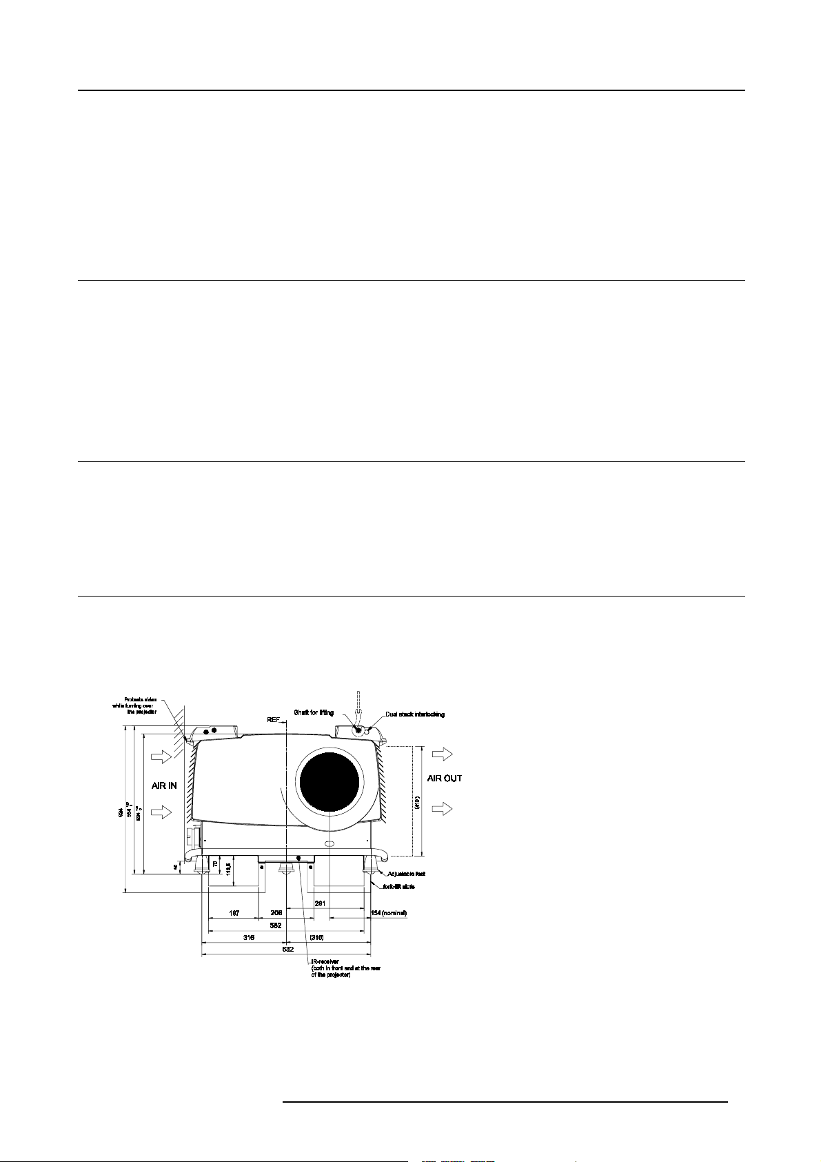
2.3 Projector Case
Dimensions
The d imensions are given in mm.
25.4mm = 1 inch
Image 2-1
Front view dimens ions
R5976333 BARCOELM R18 17092002 7
Page 12
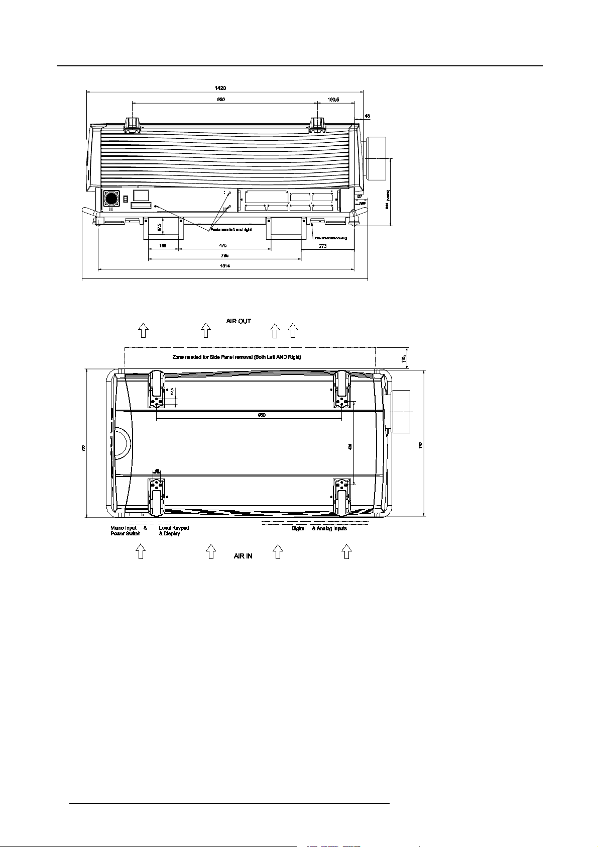
2. Packaging and Dimensions
Image 2-2
Side view dimensions
Image 2-3
Top View dimensions
8 R5976333 BARCOELM R18 17092002
Page 13
3. Installation Guidelines
3. INSTALLATION GUIDELINES
Never use the projector when turned with the inputs downwards.
3.1 General
Before installing t he projector, read first the safety instructions.
Ambient Temperature Conditions.
Careful consideration of things such as image size, ambientlight level, projector placement and type of screen to use are critical to
the optimum use of the projection system.
Max. ambient temperature : 35
Min. ambient temperature : 10
The projector will not operate if ambient air temperature falls outside this range (10
Storage temperature: -35
C or 104 F
Cor50 F
C- 35 Cor50F-10 F-95 F).
Cto+65C (-25.6 F to 149 F)
Humidity Conditions
Storage: 0 to 98 % RH Non-condensing
Operation: 0 to 95 % RH Non-condensing
Harmful Environmen tal Contamination Precaution
Environment
Do not install the projection system in a site near heat sources such as radiators or air ducts, or in a place subject to direct sunlight,
excessive dust or humidity. B e aware that room heat rises
excessive.
to the ceiling; check that temperature near the installation site is not
Environment condition check
A projector must always be m ounted in a manner which ens ures the free flow of clean air into the projectors ventilation inlets. For
installations in environments where the projector is subject to airborne contaminants such as that produced by smoke m achines or
similar (these deposit a thin layer of greasy residue upon the projectors internal optics and imaging electronic surfaces, degrading
performance), then it is highly advisable and desirable to have this contamination removed pr ior to it reaching the projectors clean
air supply. Devices or structures to extract or shield c ontaminated air well away from the projector are a prerequisite, if this is not a
feasible solution then measures to relocate the projector to a clean air env ironment should be considered.
Only ever use the manufactures recommend ed cleaning kit which has been specifically des igned for cleaning optical parts, never
use industrial strength cleaners on a projectors optics as these will degrade optical coatings and damage sensitive optoelectronics
components. Failure to take suitable precautions to protect the projector from the effects of per sistent and prolonged air contaminants will culminate in extensive and irreversible ingrained optical dam age. At this stage cleaning of the internal optical units will be
non-effective and impracticable. Damage of this nature is under no c ircumstances covered under the m anufactures warranty and
may deem the warranty null and void. In such a case the client shall be held solely responsible for all costs incurred during any
repair. It is the clients respons ibility to ensure at all times that the projector is protected from the harmful effects of hostile airborne
particles in the environment of the projector. The manufacture reserves the right to refuse repair if a projector has been subject to
wantful neglect, abandon or improper use.
Special Care for Laser Beams
Special care should be used when DLP projectors are used in the sa me r oom as performant laser equipment. Direct or indirect
hitting of a laser beam on to the lens can severely damage the Digital Mirror Devices (TM) in which case there is a loss of warranty
Which screen type ?
There are two major categories of s creens us ed for projection equipment. Those used for front projected images and those for re ar
projection applications.
R5976333 BARCOELM R18 17092002
9
Page 14

3. Installation Guidelines
Screens are rated by how much light they reflect (or transmit in the case of rear projection systems) given a determined amount
of light projected toward them. The ‘GAIN’ of a screen is the term used. Front and rear screens are both rated in terms of gain.
The gain of screens range from a white matte screen with a gain of 1 (x1) to a brus hed aluminized screen with a gain of 10 (x10)
or more. The choice between higher an d lower gain screens is largely a matter of personal preference and another consideration
called the Viewing angle. In considering the type of screen to choose, determine where the viewers will be located and go for the
highest gain screen pos sible. A high gain screen will provide a brighter picture but reduce the viewing angle. For more information
about screens, contact your local screen supplier.
What image size? How big should the image be?
The projector is designed for projecting an image size : min 1.00m (3.3ft) to max (15 m 49.2ft) (depending on the ambient light
conditions), with a aspect ratio of 4 to 3.
3.2 Configuration
Which configuration can be used?
The projector can be installed to project images in four different configurations:
• Front/table
• Rear/table
• Front/ceiling
• Rear/ceiling
10
R5976333 BARCOELM R18 17092002
Page 15
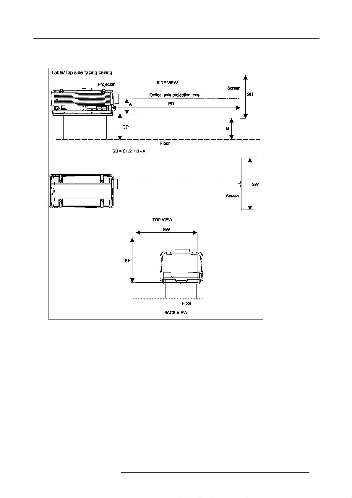
Positioning the projector
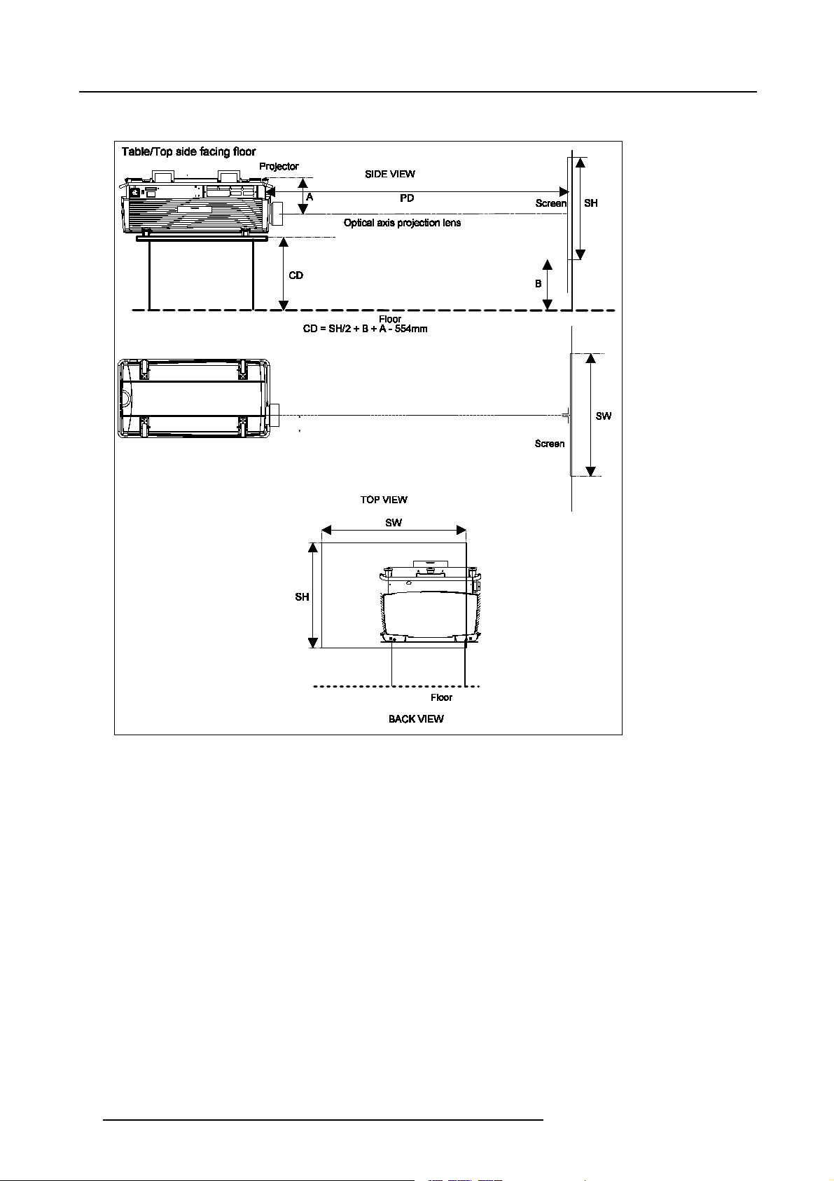
Table mounted, front projection
3. Installation Guidelines
Image 3-1
Table mounted configuration
R5976333 BARCOELM R18 17092002 11
Page 16
3. Installation Guidelines
Table mounted, front projec tion. Configuration 2
Image 3-2
Table mounted configuration
12 R5976333 BARCOELM R18 17092002
Page 17
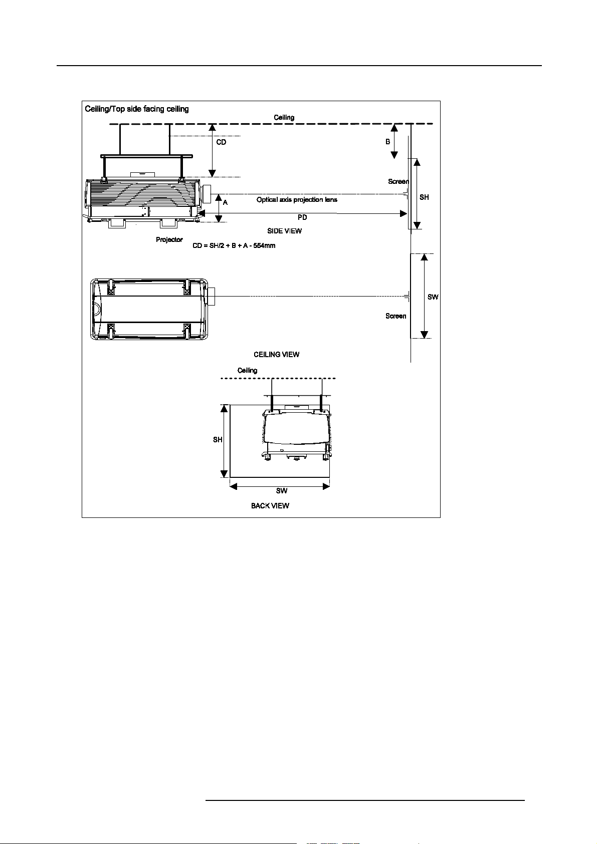
Ceiling mounted, front projection.
3. Installation Guidelines
Image 3-3
Ceiling mounted configuration
R5976333 BARCOELM R18 17092002 13
Page 18
3. Installation Guidelines
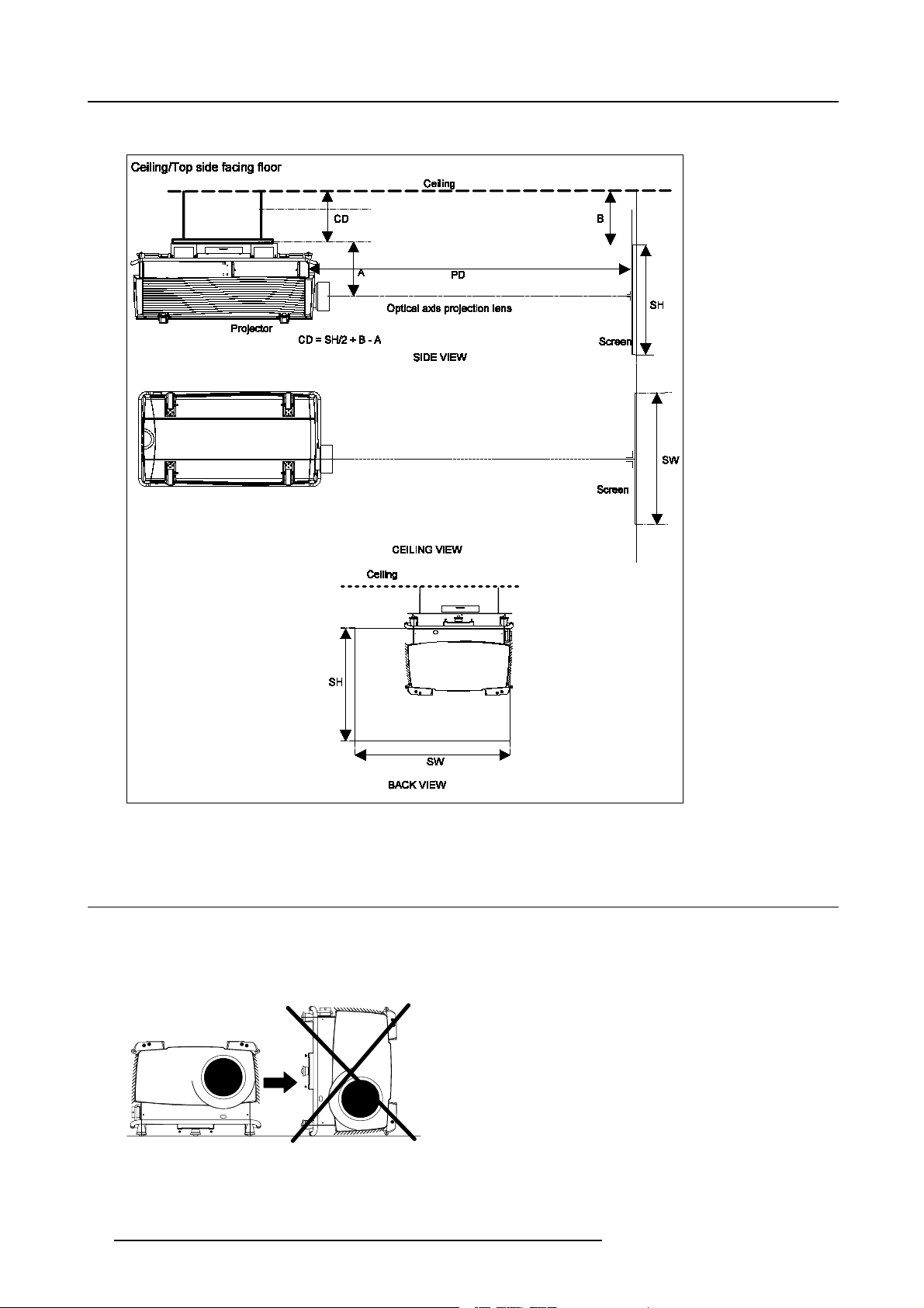
Ceiling mounted, front projection.
Image 3-4
Ceiling mounted configuration
3.3 Warning on Rotating the Projector
Warning
When the lamp casing is installed, it is not allowed to rotate the projector clockwise when facing the lenses. An internal tilt switch
will provide to start up the projector. Correct way of rotating the projector, see image 3-6.
Image 3-5
Not allowed Rotation.
14 R5976333 BARCOELM R18 17092002
Page 19
3. Installation Guidelines
Image 3-6
Rotating the Projector 180
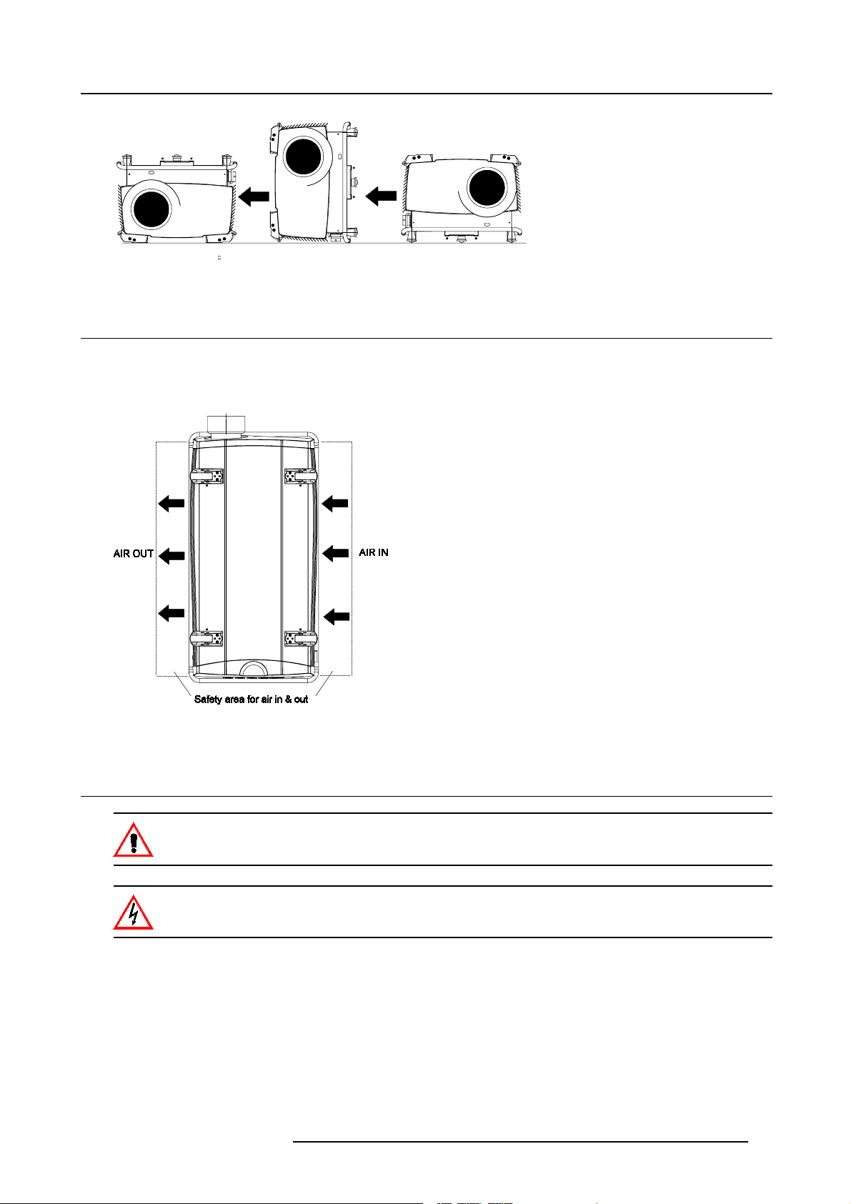
3.4 Safety Area a round ProjectorSafety Area
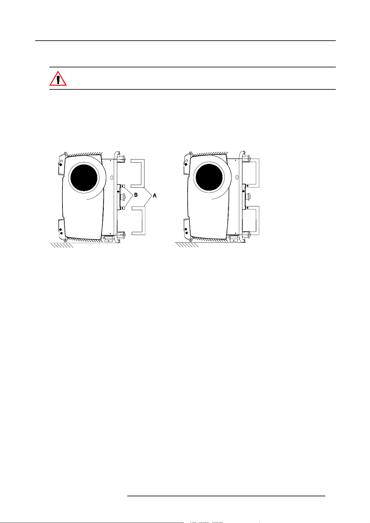
Safety area
Make sure the projector is located so that the air inlets and outlets for the cooling system are not obstructed. Leave a safety area A
of about 1 meter on the left and the right s ide of the projector.
Image 3-7
Safety area around the projector.
3.5 Installation of the Lamp Casing
Never transport the projector with the lamp casing installed. The lamp ca sing should always been transported
in a vertical way to avoid damaging the lamp.
Never attempt todisassemble the lamp from its housing or to dispose of it other than by returning it to BARCO.
Due to its high internal pressure, the lamp may explode in either hot or cold state.
Installing the p rojection lamp.
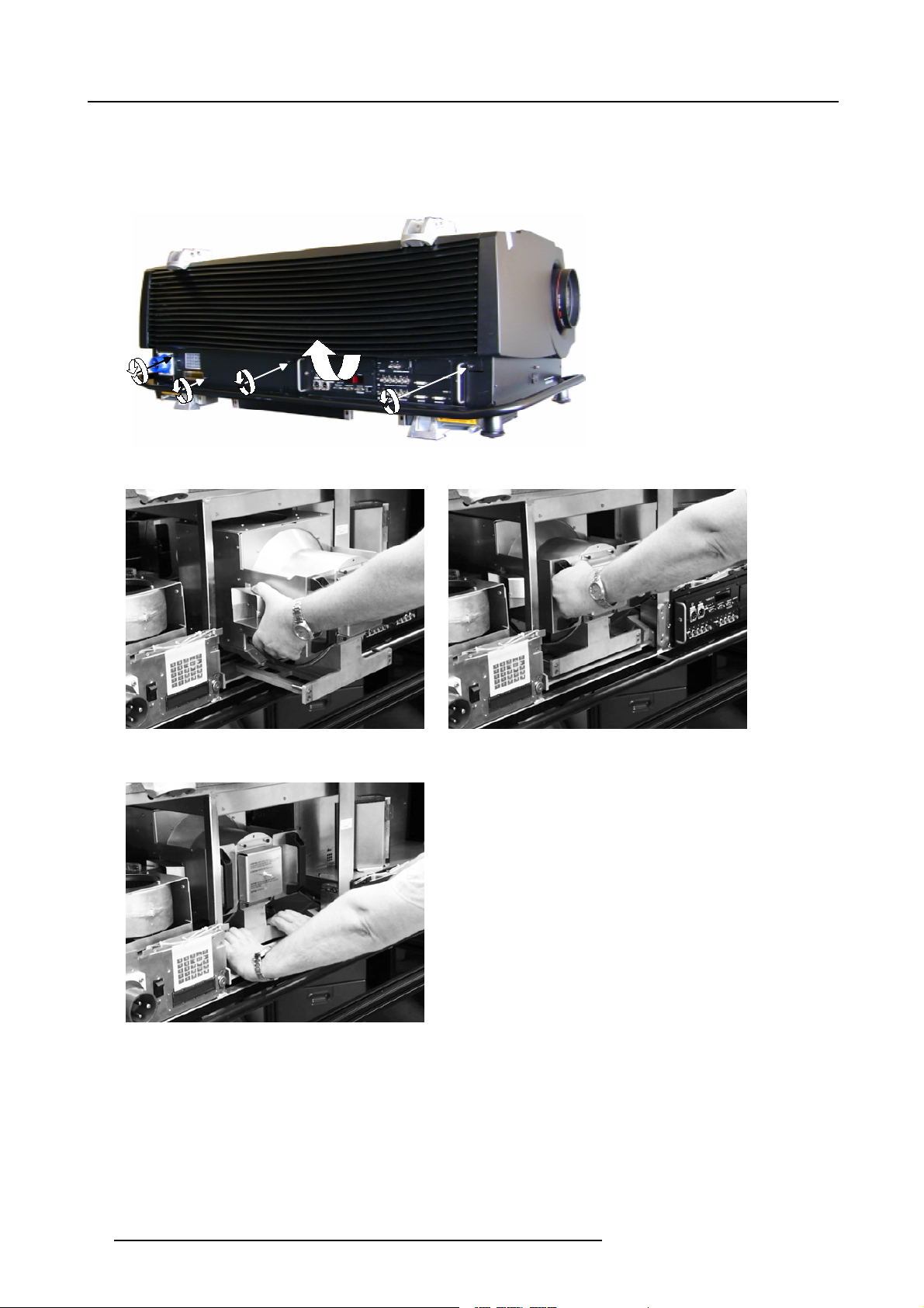
1. U nplug the projector from the wall o utlet.
2. O n the input side of the projector, remove the side by turning the 4 quarter turn fastener studs a quarter turn counter clockwise.
(image 3-8)
3. Flip the lower side of the plate a little and carefully pull it downwards to remove.
4. Take the lamp casing carefully out of its shipping box.
5. P lace the lamp casing on the optical base plate. (image 3-9)
R5976333 BARCOELM R18 17092002
15
Page 20
3. Installation Guidelines
6. P ush the lamp casing forward until the lamp slide fully into the projector. Both center pins must match both center holes. (image 3-10, image 3-11)
Both center pins must m atch both center holes. (image 3-12)
7. S ecure the correct position by turning both bolts a quarter turn clockwise.
Image 3-8
Image 3-9
Mounting the lamp casing
Image 3-11
Mounting the lamp casing
Image 3-10
Mounting the lamp casing
16 R5976333 BARCOELM R18 17092002
Page 21
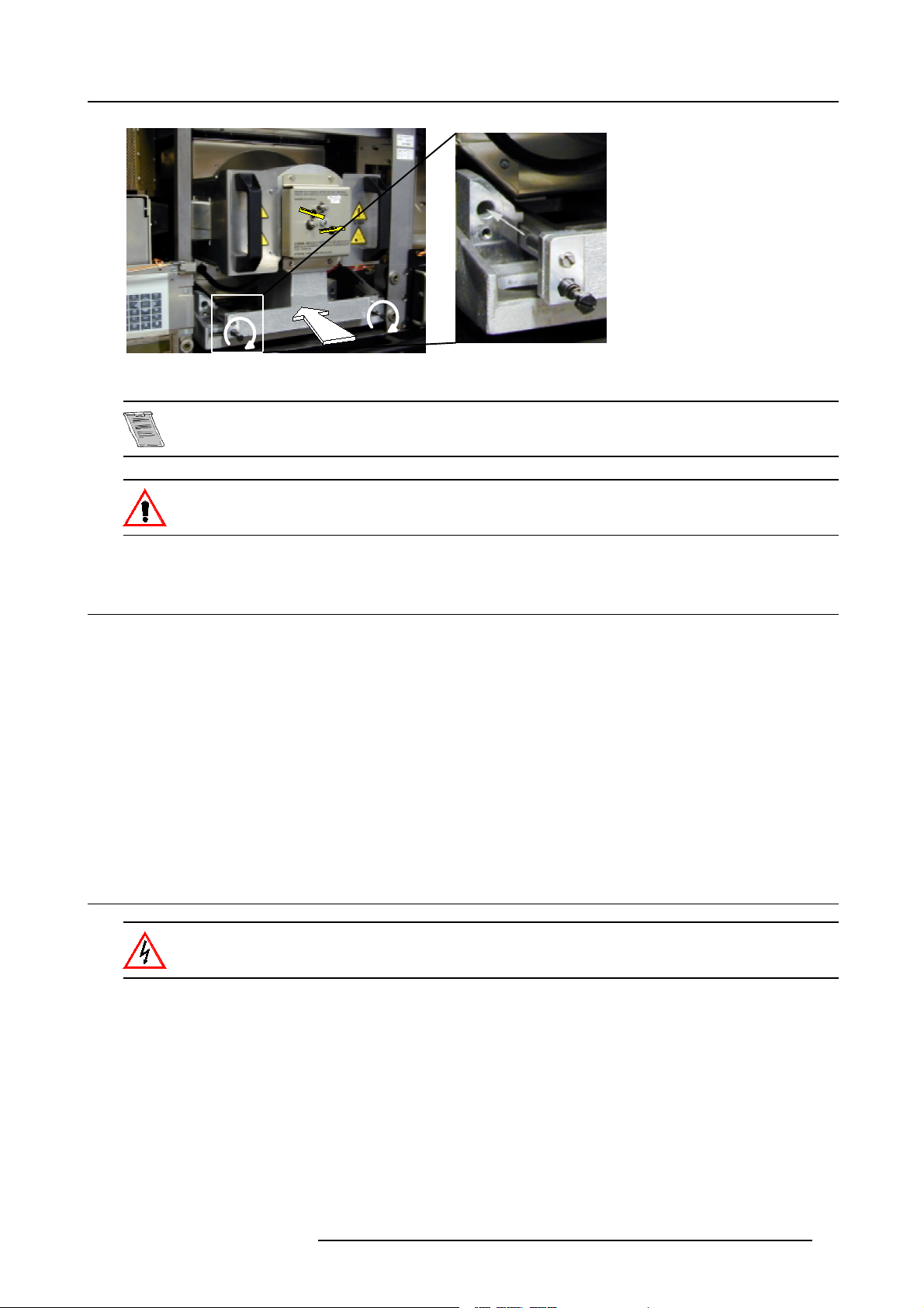
Image 3-12
Center pins must match center holes
No electrical connections have to be made while installing the lamp casing. All connections are automatically
made while inserting the lamp casing.
While starting up the projector, t he electronics detect if a lamp is installed. If no l amp is installed, it is not
possible to start up the projector.
3. Installation Guidelines
3.6 Transporting the projector
What to do?
1. S witch the projector to stand by.
2. L et cool down the projector for at least 15 minutes.
3. S witch off the projector and unplug from the wall outlet.
4. O n the input side of the projector,remove the side by turning the 3 bolts a quarter turn counter clockwise.image 3-8
5. Flip the lower side of the plate a little and pull then downward to rem ove the plate.
6. Turn the retaining bolts of the lamp a quarter counter clockwise.image 3-12
7. P ull out the lamp casing. Wear heat resistant gloves, the case can be hot.
8. P ack the lamp casing into the lamp flightcase and transport it verticaly.
3.7 Re-adjusting the lamp position in the lamp casing
As the projector has to be opened, this procedure has to be performed by qualified service technician.
Why
With higher run times, the light output of the lam p w ill dec rease, which results in a lower light output on the screen. Thislight output
decrease can be compensated by readjusting the position of the lamp.
How to readjust.
1. O n the side of the inputs, turn the 3 retaining bolts a quarter counter clockwise.
2. Flip the lower side a little backwards and take off the side cover.
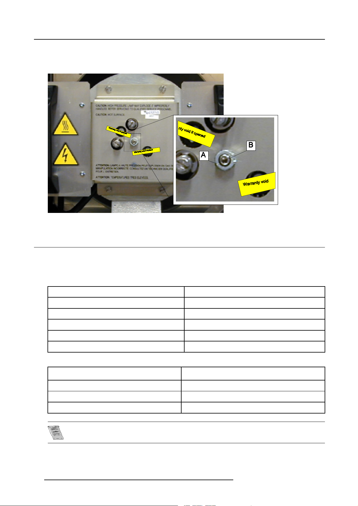
3. S tart up the adjustment mode and select Service.
4. S elect Lamp. T he Z-axis indication (lamp menu in service mode) will be helpful while turning screw B . (image 3-13)
5. L oosen the nut A (image 3-13)on the back of the lamp casing (nutdriver 10).
R5976333 BARCOELM R18 17092002
17
Page 22
3. Installation Guidelines
6. A djust the screw B (image 3-13)with an Allen key by turning a little clockwise until the maximum light output is reached (the
maximum value of the Z-AXIS indication on the lamp menu).
7. Fas ten the nut on the back of the lamp casing to secure this position (nutdriver 10).
Image 3-13
3.8 Lenses
3.8.1 Lenses
Available lenses
QLD lenses
QLD ( 1.5-2.0:1)
QLD ( 2.0-2.5:1) R9840140
QLD ( 2.5-4.0:1) R9840150
QLD ( 4.0-7.0:1) R9840160
QLD ( 5.6-12.0:1) R9840430
QLD (1.2:1)
LD lenses
LD (0.8:1) R
LD (1.5-2.5:1)
R9840130
R9840120
9840420
R9840090
LD (2.5-4.0:1) R9840270
LD (4.0-7.0:1) R9840280
These lenses can only be used in combination with an adaptor ring.
18 R5976333 BARCOELM R18 17092002
Page 23

3. Installation Guidelines
3.8.2 Lens selection
How to select ?
1. D etermine the required screen width.
2. D etermine the approximate position of the projector in t he projection room with regard to the screen a nd measure the pr ojector-
screen distance (PD).
3. U se the lens formulas to find the best corresponding PD with regard to the mea sured projector-screen distance for the required
screen width.
3.8.3 Lens Formulas
Formulas
QLD Lenses:
Metric formulas (meter ) Inch formulas (inch)
QLD (1.5-2.0:1) Min:PD=1.53xSW-0.05
Max : PD = 2.05 x SW - 0.07
QLD (2.0-2.5:1) Min : PD = 2.04 x SW - 0
Max : PD = 2.51 x SW - 0.02
QLD (2.5-4.0:1) Min:PD=2.50xSW-0.12
Max : PD = 4.01 x SW - 0.20
QLD (4.0-7.0:1) Min:PD=3.99xSW-0.05
Max : PD = 7.04 x SW - 0.23
QLD (5.6-12.0:1) Min:PD=5.64xSW±0.15
Max : PD = 12.0 x SW ± 0.15
QLD ( 1.2:1) PD = 1.24 x SW - 0.08 PD = 1.24 x SW - 3.14
LD Lenses:
Metric formulas (meter ) Inch formulas (inch)
LD (0.8:1) PD = 0.64 x SW - 0.03 PD = 0.64 x SW - 1.18
LD (1.5-2.5:1) Min:PD=1.19xSW-0.01
Max : PD = 2.01 x SW - 0.05
LD (2.5-4.0:1) Min:PD=1.97xSW-0.01
Max : PD = 3.17 x SW - 0.05
Min:PD=1.53xSW-1.97
Max : PD = 2.05 x SW - 2.76
Min:PD=2.04xSW-0
Max : PD = 2.51 x SW - 0.79
Min:PD=2.50xSW-4.72
Max : PD = 4.01 x SW - 7.87
Min:PD=3.99xSW-1.97
Max : PD = 7.04 x SW - 9.06
Min:PD=5.64xSW±5.9
Max : PD = 12.0 x S W ± 5.9
Min:PD=1.19xSW-0.39
Max : PD = 2.01 x SW - 1.97
Min:PD=1.97xSW-0.39
Max : PD = 3.17 x SW - 1.97
Lens program to calculate the projector distance is available on the BARCO webside :
h
ttp://www.barco.com/projection_systems/customer_services/lens_program.asp
3.8.4 Lens Installation
To install a pro jection lens, the projector must be switched ON.
Installation of QLD lenses :
1. R emov e the foam rubber in the opening of the lens holder.
2. S witch on the projector.
3. P ush 3x on the HELP key.
4. P ush the ↑ key to pull up the lens bridge (zoom & focus part of t he lens housing)
R5976333 BARCOELM R18 17092002
19
Page 24
3. Installation Guidelines
5. Take the new lens out of its shipping carton and remove the lens covers.
6. Turn the lens into the lens h older by turning c lockwise.
7. P ush the ↓ key to bring the lens bridge back on its position.
8. P ress EXIT to return to operational mode.
Installation of LD lenses :
LD lens will be delivered with an adapter ring.
They can be mounted in the same manner as QLD lenses.
No motorized zoom function is standard available. Toadd this motorized zoom function to the lens, a zoom ring kit has to be ordered
separately.
Zoom ring kits :
For LD(2.5-4:1) and LD(4-7:1) lens : R9840310
For LD(1.5-2.5:1) lens : R9840320
Use of lenses of compatiteurs.
The lenses of competitors can be used in this ELM projector in combination with a lens m ount adapter ring kit. This kit can be
ordered separately, order number : R9840370.
Why using an adapter ring? The ELM lens holder has been designed for QLD type lenses. These lenses in turn have been des igned
for the SXGA DLP chip. This chip is bigger than the XGA chip. In order to offer sufficient lens shift c apabilities and corner focus
performance, the diameter of the QLD lenses is larger than the LD type.
3.8.5 Cleaning the lens
To minimize the possibility o f damaging the optical coating or scratching exposed lens surface, w e have d eveloped recommenda tions for cleaning the lens. FIRST, we recommend you t ry to rem ove any material from
the lens by blowing it off with clean, d ry deionized air. DO NOT use an y liquid to clean the lenses.
Necessary tools
TorayseeTMcloth (delivered together with the lens kit). Order number : R379058.
Howtocleanthelens?
Proceed as follow :
TM
1. A lways wipe lenses with a CLEAN Toraysee
2. A lways wipe lenses in a single direction.
Warning: Do not wipe back and forwards across the lens s urface as this tends to grind dirt into the coating.
3. D o not leave cleaning cloth in either an open room or lab coa t pocket, as doing so can contaminate the cloth.
4. If smears occur when cleaning lenses, replace the cloth. Smears are the first indication of a dirty cloth.
Do not use fabric softener whe n washing the cleaning cloth or softener sheets when drying the cloth.
Do not use liquid cleaners on the cloth as doing so will contaminate the cloth.
Other lenses can also be cleaned safely with this TorayseeTMclo
cloth.
th.
3.9 Battery Installation in the RCU
How is the battery delivered ?
A battery (not yet installed to s ave the battery life time) is delivered inside the plastic bag with the power cord.
20
R5976333 BARCOELM R18 17092002
Page 25
3. Installation Guidelines
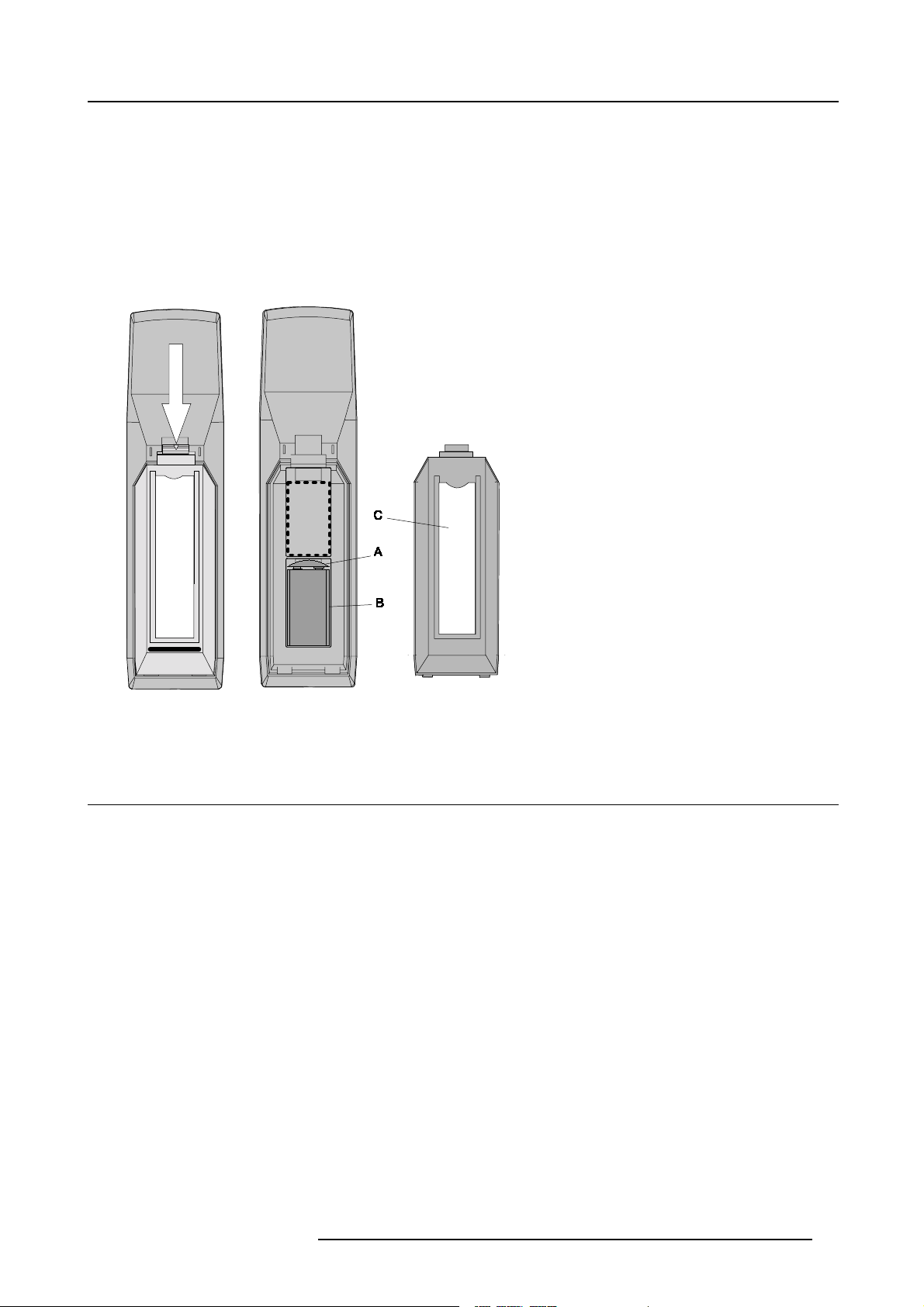
How to install ?
1. R emov e the battery cover on the backside of the remote control by pushing the indicated handle a little towards the bottom of
the R CU. (image 3-14)
2. L ift up the top side of the cover at the same time.image 3-14
3. Insert the new 9 V battery (type E -block or equivalent) in the lower compartment.
4. C onnect the battery (B) to the contact plate (A). (image 3-15)
5. Insert the battery into the lower compartment a nd put the cover back.
6. Insert a overview card (C) in the back side.image 3-15
Image 3-14
Opening the battery cover of
the RCU
Image 3-15
Mounting the battery into the RCU
3.10 Stacking Two Projectors
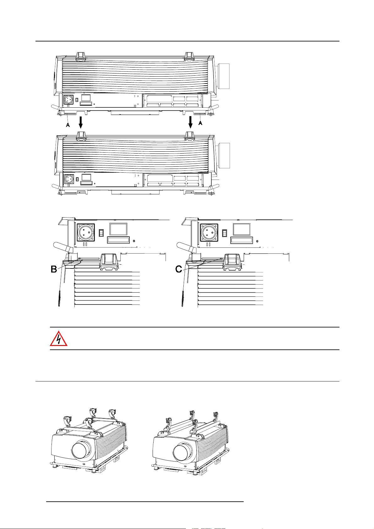
How to handle
1. P ull the handler A of the second projector a little backwards. (image 3-16)
the second projector on the first one so that base plate of the second projector matches with the rigging socket of the first
2. P ut
projector.
3. S lide the security pin (handler B) into the hole of the rigging socket of the first projector until the han dler jumps into its socket (C).
(image 3-17)
R5976333 BARCOELM R18 17092002
21
Page 26
3. Installation Guidelines
Image 3-16
Stacking two projectors
Image 3-17
Security pins
Close always the four security pins when stacking two projectors on each other.
3.11 Rigging points and Accessories.
Optional Profile Sections
Two sets of Pro file sections are available as option.
Image 3-18
Mounting profile sections
22 R5976333 BARCOELM R18 17092002
Page 27
3. Installation Guidelines
Slots are made in these profile sections for easy inserting the clamps and for easy adjusting the clamp position so that this position
matches with the rigging points.
Consult a professional structural en gineer prior to suspending the ceiling mount from a structure not intended
for that use. Always ensure the working load limit of the structure supporting the projector. When mounting
the projector to the ce iling or to a rigging system, alwa ys mount security chains.
Fork lift Supports
A set of 4 f ork lift supports are available to lift up the projector in an easy way. These supports are also provided with slot for inserting
rigging clamps.
To mount these supports, handle as follow :
1. Turn the projector onto its input side.
2. Slide t he fork lift support (A) onto the provided socket (B).
3. Turn in the four bolt f or each socket.
Image 3-19
Mounting fork lift supports
R5976333 BARCOELM R18 17092002 23
Page 28

3. Installation Guidelines
24 R5976333 BARCOELM R18 17092002
Page 29
4. Connections
4. CONNECTIONS
Overview
• Power connection
• Switching on
• Switching to standby
• Switching off
• Input Source Connec tions
• Communication Connections
4.1 Power connection
AC Power cord connection
Use the supplied power cord to connect your projector to the wall outlet. Plug the female power connector into the male connector
at the left of the projector. The power input is 230 VAC.
Fuses
For continued protection against fire hazard :
• refer replacement to qualified service personnel.
• ask to replace with the same type of fuse (T7 AH/250V).
4.2 Switching on
Howtoswitchon.
1. P ress the power switch to switch on the projector.
- W hen ’0’ is visible, the pro jector is switched off.
- W hen ’1’ is visible, the projector is switched on
The projector starts in standby mode. The projector indication lamp is red.
Starting image projection.
1. P ress Stand by key once on the local keypad or on the remote control.
The projector mode indication lamp will be green (im age 4-1)
Or,
Press a digit button to select an input source.
Image 4-1
Standby indication
R5976333 BARCOELM R18 17092002 25
Page 30
4. Connections
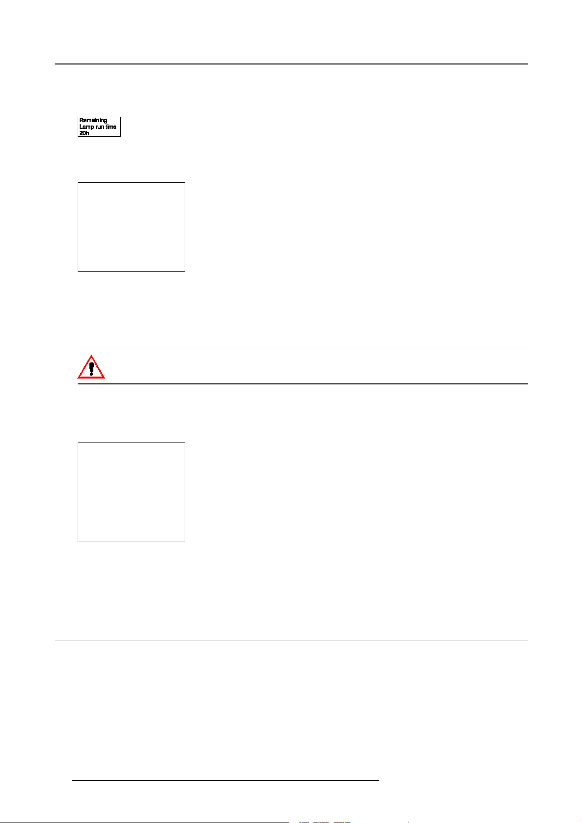
Lamp run time indication whil e running
When the total run time of the lamp is 30 hours less then 500, the following warning message will be displayed for 1 minute. This
warning message will be repeated every 30 minutes. Press EXIT to remov e the message before the minute is over.
Image 4-2
When the total run time of the lamp is 500 hours or more, the following warning message, with t he exact run time is displayed on
the sc reen.
WARNING
Lamp run time is x hours
operating the lamp longer
than x hours may damage
the projector.
Please replace the lamp
<ENTER> to continue
Menu 4-1
Lamp run time is 500 hours. Operating the lamp longer than 1000 hours ma y damage the projector. Please replace the lamp.
When ENTER is pressed to go on, the warning will be repeated every 30 min.
The total lifetime of the lamp for a safe operation is 500 hours max. Do not use it longer. Always replace with a same type of lamp.
Call a BARCO authorized ser vice technician for lamp replacement.
Using a lamp for more than 500 hours is dangerous as the lamp could explode.
Lamp Light Output Indication
When s tarting up and the center lumens measurement is lower than 50 % of its initial value, the lamp light output warning will be
displayed. Press ENTER to continue. The message will not be repeated d uri
WARNING
Lamp run time is X hours
The light output of the lamp
than 50% of its initial value.
It is advisable to replace the
Menu 4-2
is less
lamp
before damage occurs.
<ENTER> to confirm
When the ’Constant Light Output’ (CLO) options is installed, the light output message will appear on the screen when the light output
is reduced with 33% from its initial value.
This m essage will be repeated every hour.
ng operation.
4.3 Switching to standby
How to switch to standby?
1. P ress Standby to switch the projec tor to standby.
26
R5976333 BARCOELM R18 17092002
Page 31

4.4 Switching off
How to switch off the projector?
1. P res s first Standby.
2. L et cool down the projector until the fans stop blowing, at least 15 min.
3. S witch off the projector with the power switch.
4.5 Input Source Connections
4.5.1 Input Facilities
Overview input facilities
4. Connections
Image 4-3
Input facilities
Input number Type of input
1 Fixed input, 5 cable input or DVI input and DVI output
2 Fixed input, 5 cable input or DVI input
3&4 Variable inputs
Two digital inputs ava ilable.
• SDI input (R9840110)
• HD SDI Digital input (R9840450)
Digital Video Decoder (R9841170)
4.5.2 Inputs via RCVDS05
Overview
When using a RCVDS05, the input configuration must be as follows:
slot 1 RGB/Component
slot 2 Video
slot 3 not used
slot 4 not used
When using a RCVDS05, it is recommended to use a 5-cable output module in the RCV DS . The outputs of this mod ule has to be
connected to slot 1 of the projector. To switch the projector in the 5-cable mode see .
4.5.3 Input module insertion
How to insert an input module?
To insert a module in one of the free slots, handle as follow :
1. P ower down the projector and disconnect the power cord from the wall outlet.
2. R emov e the dummy plate covering the chosen input slot by turning out both screws.
3. S lide the input module in the free slot. Insure the m odule is seated correctly in the guide grooves.
R5976333 BARCOELM R18 17092002
27
Page 32

4. Connections
4. P ress on both handles of the input module until the module plug seats in the connector of the projector. (image 4-4)
5. S ecure the input module by tightening both retaining screws.
6. R econnec t the power cord to the wall outlet and switch on the projector.
Image 4-4
How to select the new installed module?
The new installed module can be selected with the digit buttons on the RCU or the local keypad.
4.5.4 Fixed slot (slot 1 & 2)
Where to find?
Slot 1 & 2 has 5 BNC input terminals for 5 cable input and a DVI plug for DVI input. Slot 1 has also an DVI output for loop through
to a seco nd projector. Within the installation mode it is possible to setup the input for 5 cable or DVI (panellink).
Which signals can be connected to slot 1 & 2?
Connector name/
Input signal
RGBHV R G B H V
RGBS R G B S
RGsB R Gs B
Composite Video
Super Video
Component Video — SS R-Y Y B-Y S
Component Video — SOY R-Y Ys B-Y
R
-
-
G
Video
Y
B H V
- -
- - -
- -
- -
-
C
-
DVI signals can be connected to the DVI input connector.
Pin assignment for the DVI connector.
Pin 1 TMDS DATA2- Pin 13 TMDS DATA3+
Pin 2 TMDS DATA2+ Pin 14 +5 Power
28
R5976333 BARCOELM R18 17092002
Page 33

Pin 3 TMDS DATA2/4 Shield Pin 15 Ground (for +5V)
Pin 4 TMDS DATA4- Pin 16 Hot Plug Detect
Pin 5 TMDS DATA4+ Pin 17 TMDS DATA0Pin 6 DDC Clock Pin 18 TMDS DATA0+
Pin 7 DDC Data Pin 19 TMDS DATA0/5 Shield
Pin 8 No connect Pin 20 TMDS DATA5Pin 9 TMDS DATA1- Pin 21 TMDS DATA5+
Pin 10 TMDS DATA1+ Pin 22 TMDS Clock Shield
Pin 1 1 TMDS D ATA1/3 Shield Pin 23 TMDS Clock+
Pin 1 2 TMDS DATA3- Pin 24 TMDS Clock-
How to select input slot 1 or 2 ?
1. K ey in 1 or 2 on the RCU or the local keypad.
How to change the input slot setting?
1. P ress ADJUST or ENTER key to start up the Adjustment mode.
2. P ush the cursor ke y ↑ or ↓ to
3. P ress EN T ER.
4. P ress the cursor key ↑ or ↓ to select Input Slots. (menu 4-4)
5. P ress EN T ER.
The internal system will scan the inputs and displays the result in the Input Slots menu.
6. P ush the cursor key ↑ or ↓ to select the first or second slot. (menu 4-5)
select Installation. (menu 4-3)
4. Connections
ADJUSTMENT MODE
Select a path from below :
RANDOM ACCESS
INSTALLATION
SERVICE
Select with↑or
then <ENTER>
<EXIT> to return
Menu 4-3
↓
Menu 4-4
INSTALLATION
INPUT SLOTS
800 PERIPHERAL
SOURCE SWITCHING
NO SIGNAL
CONTRAST ENHANCEMENT
CONVERGENCE
CONFIGURATION
LENS
QUICK ACCESS KEYS
OSD
INTERNAL PATTERNS
Select with↑or
then <ENTER>
<EXIT> to return
INPUT SLOTS
Slot Module type [config]
1. RGB-SS [CV]
2. RGB-SOG
3. SDI
4. SDI
______________
1. DVI OUTPUT [DVI input]
↓
Menu 4-5
Select with↑or
then <ENTER>
<EXIT> to return
↓
Possible indications on the input slot menu.
For the input side:
• RGS-SS [CV or HS&VS] = RGB analog signals, separate sync is composite sync or horizontal and v ertical sync.
• RGB-SS [CV] = RGB analog signals, separate sync is composite video.
• RGB-SOG [SOG or 3LSOG ] = RGB analog signals, s ync on green is composite sync or composite tri-level sync.
• COMPONENT VIDEO - SS [SS or 3LSS] = separate sync is c ompos ite sync or composite tri-level sync.
• COMPONENT VIDEO - SOY [SOY or 3LSOY] = component video with comp osite sync on Y or composite tri-level sync on Y.
•VIDEO
•S-VIDEO
•DVI
When changing from an analog signal on the 5 cable module to the panellink input the indication led on the front panel of the module
will switch from the 5 cable input to the DVI (panellink) input also.
For the output on fixed slot 1:
• DVI input : DVI in signal is looped through to the DVI out connector as it is.
• Active image : active image signal, what ever the input is, is available in DVI on the DVI outputsignal (processing is incorporated
in the signal). Set the minimum delay in Installation > Advanced processing to OFF.
R5976333 BARCOELM R18 17092002
29
Page 34

4. Connections
When using an RCVDS 05 with a 5 cab le output module, connect these 5 cables to this fixed 5-input slot (slot1)
of the p rojector. All sources of the RCVDS can now be accepted by the projector.
4.5.5 Serial Digital Input (slot 3 & 4)
What can be connected to this input?
This input is full compatibility with digital Betacam , or other digital video sources. This av oids the need for analog video p rocessing
anywhere in the video production chain and guarantees the ultimate image quality.
An active loop-through of the SDI input signal is provided for monitoring or for double and or triple stacking applications.
How to connect ?
1. C onnect the output of your SDI source to the input BNC of the SDI input. (image 4-5)
Note: The input is always 75 Ω terminated.
2. If loop through is needed, use the OUT to connect to the next device.
Image 4-5
How to select the digital input?
1. K ey in the corresponding slot num ber on the R CU or the local keypad.
When a RCVDS 05 is connected to the projector, the S
DI input is available by keying in 83 or 84 on the RCU.
4.5.6 HD SDI Digital input (slot 3 & 4 )
What can be connected to this input?
This input is full compatibility with HD digital sources. This avoids the need for analog video processing anywhere in the video
production chain and guarantees the ultimate image quality.
An active loop-through of the HD SDI input signal is provided for monitoring or for do uble and or triple stacking applications.
How to connect ?
1. C onnect the output of your HD SDI source to the input BNC of the HD SDI input. (image 4-6)
Note: The input is always 75 Ω terminated.
2. If loop through is needed, use the OUT to connect to the next device.
30
R5976333 BARCOELM R18 17092002
Page 35

Image 4-6
How to select the digital input?
1. K ey in the corresponding slot num ber on the R CU or the local keypad.
When a RCVDS 05 is connected to the projector, the SDI input is available by keying in 83 or 84 on t he RCU.
4. Connections
4.5.7 Digital Video De coder Input
What can be connected to this input?
The following source types can be conne cted:
• S-Video
• Component Video
• Composite Video
Which signal can be connected to the Dig ital Video Decoder module?
Connector name/
Input signal
Component Video B-Y Ys R-Y
Composite Video
S-Video
Pb
-
- - -
Y/Vid
Video
Pr
- -
How to connect?
1. C onnect the output of your source to the corresponding inputs on the Digital Video Decoder module. (im age 4-7)
S-Video
-
S-Video
Image 4-7
1 Component video input
2 Composite Video input
3 S-Video input
How to select the digital video decoder input?
1. K ey in the corresponding slot num ber on the R CU or the local keypad.
R5976333 BARCOELM R18 17092002
31
Page 36

4. Connections
How to change the input slot setting?
1. P ress ADJUST or ENTER key to start up the Adjustment mode.
2. P ush the cursor ke y ↑ or ↓ to select Installation. (menu 4-6)
3. P ress EN T ER.
4. P ress the cursor key ↑ or ↓ to select Input Slots. (menu 4-7)
5. P ress EN T ER.
The internal system will scan the inputs and displays the result in the Input Slots menu.
6. P ush the cursor key ↑ or ↓ to select the third or fourth slot. (menu 4-8)
7. P ress ENTER to toggle.
Possible indications on the input slot menu.
- VIDEO[VDEO]
- VIDEO[S-VIDEO]
- VIDEO[YUV]
ADJUSTMENT MODE
Select a path from below :
RANDOM ACCESS
INSTALLATION
SERVICE
Select with↑or
then <ENTER>
<EXIT> to return
Menu 4-6
↓
Menu 4-7
INSTALLATION
INPUT SLOTS
800 PERIPHERAL
SOURCE SWITCHING
NO SIGNAL
CONTRAST ENHANCEMENT
CONVERGENCE
CONFIGURATION
LENS
QUICK ACCESS KEYS
OSD
INTERNAL PATTERNS
Select with↑or
then <ENTER>
<EXIT> to return
INPUT SLOTS
Slot Module type [config]
1. RGB-SS [CV]
2. RGB-SOG
3. SDI
4. SDI
______________
1. DVI OUTPUT [DVI input]
↓
Menu 4-8
Select with↑or
then <ENTER>
<EXIT> to return
↓
4.6 Communication Connections
Overview
• RS232 (RS422) Connection
• Communication with p eripherals
• Network connection
4.6.1 RS232 (RS422) Connection
Application
1. Remote control :
- easy adjustment of projector via an IBM P C (or compatible) or MAC connection.
- allow storage of m u ltiple projector configurations and set ups.
- wide range of control possibilities.
- address range from 0 to 255.
2. data communications : sending data to the projector or copying the data from the projector to a hard memory device (hard disc,
floppy, etc.).
Set up of the Baud Rate for communication with a computer.
see B aud rate Setting, page 92.
4.6.2 Communication with peripherals
What is possible with an RCVDS05 connected.
• Up to 20 inputs with the RCVDS 05 and 90 inputs when RCVDS’s are linked via the expansion module.
• Serial commu nication with the projector.
• Remote control buttons on the RCVDS to control the pro jector (source selection and analog settings).
• The selected source number will be displayed on a 2 digit display
on the rear.
For more information about the use of the RCVDS 05, consult the owner’s manual of the RCVDS05.
32
and the selected input module will be indicated with a LED
R5976333 BARCOELM R18 17092002
Page 37

4. Connections
What is possible with an VS05 connected.
The VS05 can switch up to 5 Composite Video sources, 3 Super Video sources and 1 RGB analog or component video source to
the projector. In addition, the audio signal proper to the source, can be switched to an audio amplifier. Order number : R9827890
For more information about the use of the VS05, consult the VS05 owner’s manual.
Connecting an IR Remote Receiver to the projector.
This infrared receiver unit makes it pos sible to control the projector from another room. There is a comm unication line cable between
the IR receiver and the projector or the RCVDS. The control information from the RCU can now be sent to the IR
The IR Remote Receiver displays the selected source on a 7-segment display.
Remote Receiver.
Connecting a Rugged Remote to the projector.
The Rugged Remote Control allows following functions:
• Remote mode : sends actions to and reads information from t he projector.
• Lamp read mode : reads information stored in the lamp information module.
The following types of Rugged Remote Control are available:
• wireless (order number R9840171)
• wired to CTRL3 (order number R9840170)
For more information about the use of this remote control, consult the us er manual R59 76251.
4.6.3 Network connection
Only 10 Base-T connection
What can be done?
When the optional network connection is installed, the projector can be connected to a LAN (local area network ) (ethernet). Once
installed and connected to the LAN, users are capable of ac cessing the projector from any location, inside or outside their company
network from a standard web browser. The projector acts as web server and generates a webside with all functions of the projector
listed. Via an internet explorer 4.0 or higher,or a Netscape communicator, the user can insert the correct IP-address of the projector
and access the webpages. Oncethe webside is accessed, it is possible to check and manipulate all the projector settings. R emote
diagnostics, control and m onitoring of the projector can then become a daily and very simple operation. The network connectivity
permits to detect potential e rrors and c onsequently improve the time to servicing.
Image 4-8
Always use an ethernet cable with ferrite core to connect the projector to the LAN.
R5976333 BARCOELM R18 17092002 33
Page 38

4. Connections
34 R5976333 BARCOELM R18 17092002
Page 39

5. Getting Started
5. GETTING STARTED
5.1 RCU & Local keypad
How controlling the projector ?
The projector can be controlled by the local keypad or by the remote control unit.
Location of the local keypad ?
The local keypad is located on the input side of the pro jector.
Remote control functions.
This remote control includes a battery powered infrared (IR) transmitter that allows the user to c ontrol the projector remotely. This
remote control is used for source selection, control, adaptation and set up. It includes automatic storing of picture controls (Brightness, Sharpness...) and settings.
Other functions of the remote c ontrol are :
• switching between stand by and opera tional mode.
• switching to "pause" (blanked picture, full power for immediate restarting)
• direct access to all connected sources.
5.2 Terminology overview
Overview
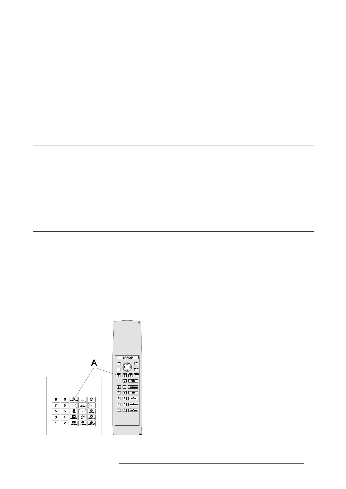
The following table gives an overview of the different functionalities of the keys.
Image 5-1
Local keypad & RCU
R5976333 BARCOELM R18 17092002 35
Page 40

5. Getting Started
1 Barco key selection key, to get direct access to the lens adjustment men us.
2 ADJ ADJUST key, to enter or exit the adjustment mode.
3 Address key (recessed key), to enter the address of the projector (between 0 and 9). Press the
4 STDY stand-by button, to start projector when the power switch is switched on and to switch
5 PAUSE to stop projection for a short time, press ’PAUSE’. The image disappears but full power
6 Help n line help information (n ot yet available)
7 Digit buttons direct input selection
8 Picture controls use these buttons to obtain the desired picture analog level.
9 PHASE used to remove the instability of the image.
10 TEXT when adjusting one of the image, e.g. controls during a meeting, the displayed bar
11 FREEZ press to freeze the projected image.
12 ENTER to start up the adjustment mode or to confirm an adjustment or selection in the
13 EXIT to leave the adjustment mode o r to scroll upwards when in the adjustment mode.
14 Cursor keys (onRCU) or ’+’ and ’-’ keys (cursor keys) on the local k eypad : to make menu selections
recessed address key with a pencil, followed by p ressing one digit button between
0 and 9.
off the projector without sw itching off the power switch.
is retained for immediate restarting.
scale can be removed by pressing ’TEXT’ key first. To re-display the bar scale on the
screen, press ’TEXT’ key again. When TEXT is ’off’, no adjustment menu’s will be
displayed on the screen when entering the adjustment mode.
adjustment mode.
when in the adjustment mode or to zoom/focus when the direct access is ac tive.
Comparison between the cursor keys and the use of the ’+’ and ’-’ keys on the local
keypad : RCU = local keypad
cursor key up = ’+’ k ey up
cursor key down = ’-’ key down
cursor key right = ’+’ key right
cursor key left = ’-’ key left
Use the ’+’ and ’-’ keys (cursor k eys) : to increase or decrease the analog level of the
image controls when they are first s elected.
15 RC Operating indication lights up when a button on the remote control is pressed. (This is a visual indicator to
Table 5-1
check the operation of the remote c ontrol)
5.3 Operating the projector
5.3.1 Switching on
Howtoswitchon.
1. P ress the power switch to switch on the projector.
- W hen ’0’ is visible, the pro jector is switched off.
- W hen ’1’ is visible, the pro jector is switched on.
The projector starts i standby mode.
Starting image projection.
1. P ress Stand by key once on the local keypad or on the remote control.
The proj
Or,
Press a digit button to select an input source.
36
ector mode indication lamp will be green (image 5-2)
R5976333 BARCOELM R18 17092002
Page 41

Image 5-2
Lamp Run time indication
see chapter 4. Connections, Switching on , page 25
Lamp Light output indication
see chapter 4. Connections, Switching on , page 25
5. Getting Started
5.3.2 Switching to standby
How to switch to standby?
1. P ress Standby to switch the projec tor to standby.
Switchingto Standby. When the projector is running and you want to go to standby, press the standby key for
2 seconds un til the message ’Saving data, please wait’ is displayed. Do not press any longer on the standby
key otherwis e the projector will restart.
5.3.3 Switching off
How to switch off the projector?
1. P res s first Standby.
2. L et cool down the projector until the fans stop blowing, at least 15 min.
3. S witch off the projector with the power switch.
5.3.4 Temperature error DMD
Overview
When the tempera ture of one of the DMD is too low or too high the projector will be switched automatically to standby. Before
switching to standby, the following message a
Automatic shutdown is activated.’.
A ’-t’ appears on the LED display to indicate the user that the projector is switched to standby due to DM D temperature problems.
Operating temperature range of the DMD : +10
ppears for 3 s econds on the screen : ’DMD out of operating temperature range.
C and +40 C.
R5976333 BARCOELM R18 17092002
37
Page 42

5. Getting Started
ERROR
DMD out of operating
temperature
range
Automatic shutdown is
activated
Menu 5-1
5.4 Quick Set up Adjustment
Overview
• Quick Language Change
• Quick Lens Adjustment
• Quick O n Screen Co lor change
5.4.1 Quick Language Change
What can be done?
Only if different on screen languages are available, these can be changed in quick wa y by following the next procedure.
How to change
1. P ress ENTER to start up the adjustment mo de.
2. P ress the cursor key ↑ or ↓ to highlight Service. (menu 5-2)
When password protected, your password will be asked. (moreexplanation about access by password can be found in Chapter
’Start up the Adjustment mode’.
3. P ress ENTER to display the Service mode menu.
4. P ush the cursor key ↑ or ↓ to highlight Change Language . If not visible in the menu, highlight first More and press ENTER to
display a second service menu. Select then Change Language. (menu 5-3)
5. P ress ENTER to display the language selection menu.
6. P ush the cursor key ↑ or ↓ to highlight the desired language. (menu 5-4)
Note: For the moment, only English is a vailable.
ADJUSTMENT MODE
Select a path from below :
RANDOM ACCESS
INSTALLATION
SERVICE
Select with↑or
then <ENTER>
<EXIT> to return
Menu 5-2
↓
Menu 5-3
SERVICE
IDENTIFICATION
CHANGE PASSWORD
CHANGE LANGUAGE
CHANGE PROJ. ADDRESS
SERIAL COMMUNICATION
NETWORK
LAMP
MORE...
Select with↑or
then <ENTER>
<EXIT> to return
CHANGE LANGUAGE
ENGLISH
↓
Menu 5-4
Select with↑or
then <ENTER>
<EXIT> to return
↓
5.4.2 Quick Lens Adjustment
Quick zoom/focus adjustment
1. P ress the Selection key *,Barcokey.
The zoom/focus menu will be displayed. (image 5-3)
2. P ush the cursor key ↑ or ↓ to zoom and ← or → to focus the image.
3. W he n finished, press EXIT key to return or ENTER to continue to the shift adjustment.
38
R5976333 BARCOELM R18 17092002
Page 43

Image 5-3
Quick shift adjustment
1. P ress the Selection key *,Barcokey.
The zoom/focus menu will be displayed. (image 5-4)
2. P ress EN T ER.
The shift menu will be displayed.
Or,
Push th e cursor key ↑ or ↓ to shift the image up or down and ← or → to shift the im age left or right.
3. W he n finished, press EXIT key to return or EN TE R to continue to tilt adjustment.
5. Getting Started
Image 5-4
Quick tilt adjustment
1. P ress the Selection key *,Barcokey.
The zoom/focus menu will be displayed. (image 5-5)
2. P ress EN T ER.
The shift menu will be displayed.
3. P ress EN T ER.
The tilt m enu will be displayed.
4. P ush the cursor key ↑ or ↓ to tilt the image.
5. W he n finished, press EXIT key to return.
Image 5-5
5.4.3 Quick On Screen Color change
What can be done ?
For quick change of the on-screen color of the highlighted items.
The highlighted items on the menus can be displayed in red , green or yellow.
R5976333 BARCOELM R18 17092002
39
Page 44

5. Getting Started
How to change ?
1. P ress ENTER to start up the adjustment mo de.
2. P ush the cursor key ↑ or ↓ to highlight Installation. (menu 5-5)
3. P ress ENTER to select.
4. P ush the cursor key ↑ or ↓ to highlight OSD. (menu 5-6)
5. P ress ENTER to select.
The OSD menu will be displayed. (menu 5-7)
6. P ush the cursor key ↑ or ↓ to highlight Highlighted item color.
7. P ress ENTER to toggle between red, green and yellow.
ADJUSTMENT MODE
Select a path from below :
RANDOM ACCESS
INSTALLATION
SERVICE
Select with↑or
then <ENTER>
<EXIT> to return
Menu 5-5
↓
Menu 5-6
INSTALLATION
INPUT SLOTS
800 PERIPHERAL
SOURCE SWITCHING
NO SIGNAL
CONTRAST ENHANCEMENT
CONVERGENCE
CONFIGURATION
LENS
QUICK ACCESS KEYS
OSD
INTERNAL PATTERNS
Select with↑or
then <ENTER>
<EXIT> to return
↓
5.5 Using the RCU
Pointing to the reflective screen
1. P oint the front of the RCU to the reflective screen surface. (image 5-6)
OSD
HIGHLIGHT ITEM COLOR [red]
MENU POSITION [Default]
Select with↑or
then <ENTER>
<EXIT> to return
Menu 5-7
↓
Image 5-6
Hardwired Remote Input
1. P lug one end of the remote cable in the connector on the bottom of the R CU.
2. P lug the other end in the connector in the front panel of the projector labelled RC . (image 5-7)
40 R5976333 BARCOELM R18 17092002
Page 45

5. Getting Started
Image 5-7
Hardwired to the XLR input
1. P lug one end of the remote cable in the connector on the bottom of the RCU
2. P lug the other end in the connector in the front panel of the projector labelled Hardwired CTRL2. (image 5-8)
Image 5-8
Directly to one of the IR sensors
When using the wireless remote control, make sure you are within the effectiveoperating distance (30m, 100ft in a straight line). The
remote control unit will not function properly if strong light strikes the sensor window or if there are obstacles between the remote
control unit and the projector IR sensor.
R5976333 BARCOELM R18 17092002
41
Page 46

5. Getting Started
Image 5-9
5.6 Projector Address
5.6.1 Controlling the projector
Projector address
Address installed in the projector to be individually controlled.
Common address
Default address. Projector will always execute the comm and coming from a RCU programmed with that common
address.
Why a projector address ?
As more than one projector can be installed in a room, the separate projector should be separately addressable with an RCU or
computer. There for each projector has its own address.
Set up an individual Projector Address.
The set up of a projector ad dress can
Projector controlling.
Every projector requires an individual add ress between 0 and 255 which can be s et in the Service mode.
When the address is set, the projector can be controlled now:
• RCU for addresses between 0 and 9.
• computer, e .g. IBM PC (or compatible),
be done via the software. See ’Change projector address’ in chapter ’Service mode’.
Apple MAC, etc. for addresses between 0 and 25 5.
Common Address
Every projector has a common address ’0’ or ’1’. The choice between ’0’ and ’1’ can be s elected in the Ser vice mode.
42
R5976333 BARCOELM R18 17092002
Page 47

5.6.2 Displaying and Programming addresses
Displaying the Projector Address on the Screen.
1. P ress Address key (recessed key on the RCU) with a pencil.
The p rojector’s address will be displayed in a ’Text box’
To continue using the RCU with that specific address, it is necessary to enter the same add ress with the
digit buttons (address between 0 and 9) within 5 seconds after pushing the address key. For example : if the
Address key displays projector address 003, then press "3" digit button on the RCU to set the RCU’s address
to match the projector’s ad dress. Do not press 003 digits. This will ad dress the remote control to ’0’ and
control all projectors in the room. Ifthe address is not entered within 5 seconds, the RCU returns to its default
address (zero address) and con trol all p rojectors in the room .
How to Program an Address into the RCU?
1. P ress the Address key (recessed key on the RCU) with a pencil.
2. E nter the address with the digit buttons within 5 seconds after pushing the address key.
Note: That address can be any digit between 0 and 9.
5. Getting Started
R5976333 BARCOELM R18 17092002
43
Page 48

5. Getting Started
44 R5976333 BARCOELM R18 17092002
Page 49

6. Start up of the Adjustment mode
6. START UP OF THE ADJUSTMENT MODE
6.1 Start up
Possible paths
There are 3 pos sible paths to follow once in the Adjustment mode. They are :
• Installation - Installation should be selected if a new input m odule is installed or a new source is connected to an existing input
module. Also when the projector is relocated in a new configuration.
• Random Access - Random Ac cess should be selected to s et up a new source.
• Service - Service should be selected if the user intends to change general settings such as password, language, address, etc.or
some s ervice actions or get set-up information.
How to start up.
1. P ress ADJUST or ENTER to enter the Adjustment mode.
The adjustment mode opens. (m enu 6-1)
2. The cursor key (RCU) or ’+ or ’-’ keys (local keypad) are used to make menu selections and also for adjustments.
3. The ENTER and EXIT keys are used to move forward and backward through the menu structure.
4. The ADJUST k ey can be used to terminate the adjustment mode while any path selection menu is displayed.
ADJUSTMENT MODE
Select a path from below :
RANDOM ACCESS
INSTALLATION
SERVICE
↓
Menu 6-1
Select with↑or
then <ENTER>
<EXIT> to return
6.2 Password
Password protection of some items.
Some items in the A djustment mode are password protected. While selecting such an item, the p rojector asks to enteryour password
(Password protection is only available when the password strap on the controller module is ON, call an authorized service center to
change the position of the password strap).
R5976333 BARCOELM R18 17092002
45
Page 50

6. Start up of the Adjustment mode
Entering your password
1. Th e first digit position is highlighted. Enter the first digit. (menu 6-2)
The highlighted square jumps to the next position.
2. C ontinue with the other digits
Example : 2 3 1 9
When y our password is correct, you gain access to the selected item.
When your password is wro ng. The error message Invalid password is displayed on the screen. P ress EXIT to continue and to
return to the adjustment menu.
PASSWORD
ENTER PASSWORD
----
Use numeric keys
<EXIT> to return
Menu 6-2
Factory programmed password : 0 0 0 0
Password remark
When re-entering the Adjustment mode, it will be necessary to enter the password again when selecting a password protected item.
Changing your password
To change your password, see chapter Service Mode, Change Password.
6.3 Menus on Local LCD Display
Overview
When text is ’off’, no menus will be displayed on the projection s creen . But on the local LCD display, it is still possible to scroll
through the men us. The menus will be displayed line by line in the same order as they were displayed on the projection screen.
Adjustments can be done wh ile the projector is running without pr ojecting the disturbing menu s on the screen.
Use the cu rsor keys to scroll through the menus and press ENTER to a
ctivate the displayed menu.
46
R5976333 BARCOELM R18 17092002
Page 51

7. Random Access Adjustment Mode
7. RANDOM ACCESS ADJUSTMENT MODE
Overview
• Overview Flow
• Picture Services
• Picture Tuning
• Geometry
• ScenergiX
• Picture in Picture (PiP)
7.1 Overview Flow
Overview
Image 7-1
R5976333 BARCOELM R18 17092002 47
Page 52

7. Random Access Adjustment Mode
Start up
1. P ush the cursor key ↑ or ↓ to highlight R andom Access. (menu 7-1)
2. P ress ENTER. (menu 7-2)
ADJUSTMENT MODE
Select a path from below :
RANDOM ACCESS
INSTALLATION
SERVICE
Select with↑or
then <ENTER>
<EXIT> to return
Menu 7-1
↓
Menu 7-2
RANDOM ACCESS
ADJUSTMENT MODE
FILE SERVICE
PICTURE TUNING
GEOMETRY
SCENERGIX
PIP
Select with↑or
then <ENTER>
<EXIT> to return
↓
7.2 Picture Services
7.2.1 File annotation
How a file is built up
The file notation on a menu is built up in different parts. Let us hav e a look to these parts.
Take the following notation : xxxxxxxx.eee n ppppXppppi
xxxxxxxx
eee
n
base name, 8 characters
file extension
first character C : custom made file
first character S : standard file
The second and third character is used for a following num ber (= file
index). The file index for cus tom files : 00 to 63.
source number
ppppXpppp active pixel rating
i i or blank
i = interlaced file
blank = not interlaced
Table 7-1
7.2.2 Possible file manipulations
Connecting a new source.
Before using a new source, a correct file has to be installed. The projector’s memory contains a list of files corresponding to the most
used sources. When the new source corresponds with one of these files, the file can be loaded and saved for future use. When
there is a little difference, the file can also be loaded and then edited until the source specs are reached.
file loading can be done autom atically (see File Options, page 56). Files with a ~ in front of the file name are
temporary files. These files will be deleted when switching to an other source.
48 R5976333 BARCOELM R18 17092002
Page 53

Possible fi le Manipulations
The following file manipulations are possible :
• Load : installation of a file for a new source.
• Edit : editing a loaded file to the source specs.
• Rename : renaming a file.
• Copy : copying a file.
• Delete : deleting a file
• Options : way of sorting the files.
7.2.3 Start up
Start up
To enter the File Service, handle a s follow :
1. P ush the cursor key ↑ or ↓ to highlight File Service. (menu 7-3)
2. P ress ENTER to select.
The File Service menu will be displayed. (menu 7-4)
7. Random Access Adjustment Mode
Menu 7-3
RANDOM ACCESS
ADJUSTMENT MODE
FILE SERVICE
PICTURE TUNING
GEOMETRY
SCENERGIX
PIP
Select with↑or
then <ENTER>
<EXIT> to return
↓
Menu 7-4
FILE SERVICE
Select with↑or
then <ENTER>
<EXIT> to return
7.2.4 Load file
Start up Load file
To start up the load file, handle as follow :
1. P ush the cursor key ↑ or ↓ to highlight Load. (menu 7-5)
2. P ress ENTER to select.
The Load menu displays the corresponding files depending on the installed filter. (menu 7-6)
FILE SERVICE
LOAD
EDIT
RENAME
COPY
DELETE
OPTIONS
F
video525.s01 1 675x240i
video525.c01 1 675x240i
video525.c02 1 675x240i
---------------------------Active file : Video525.c50
LOAD FILE
FILTER LIST [All]
ilename Src resolution
LOAD
EDIT
RENAME
COPY
DELETE
OPTIONS
↓
Menu 7-5
Select with↑or
then <ENTER>
<EXIT> to return
↓
Select with↑or↓,
<ENTER> to accept
<EXIT> to return
Menu 7-6
Changing the filter setting
1. Push the cursor key ↑ or ↓ highlight filter list.
2. P ress ENTER to toggle the annotation between brackets.
[All] : all files that can be loaded will be displayed.
[Fit] : only the best fitting files will be d isplayed (with a distinction of ± 2 lines and line duration of ± 300 ns, if nothing is found
within this small area, the pr ojector continues s earching until it finds something).
R5976333 BARCOELM R18 17092002
→
49
Page 54

7. Random Access Adjustment Mode
Howtoloadafile?
1. P ush the cursor key ↑ or ↓ to select the bes t fitting file. (menu 7-7)
2. P ress ENTER to select.
A confirm Load file menu will be displayed with the newly created file and the one on which the new file is based on. (menu 7-8)
3. P ress ENTER to confirm the new creation or EXIT to return to the load file menu.
LOAD FILE
FILTER LIST [All]
F
ilename Src resolution
video525.s01 1 675x240i
video525.c01 1 675x240i
video525.c02 1 675x240i
---------------------------Active file : Video525.c50
Select with↑or↓,
<ENTER> to accept
<EXIT> to return
Menu 7-7
→
Menu 7-8
CONFIRM
LOAD FILE
create file
Video525.c02
based on file
Video525.s01?
<ENTER> to return
<EXIT> to return
During a load file, the actual file is displayed next to the indication Active file.
When scrolling through the files, the image will be adapted according to the settings of the selected file ( on
line adap tation.
The image is not perfect ?
If the displayed image is not correct after selecting the best fitting file, g o to the Edit menu, select the active file and change the File
settings.
7.2.5 Edit File
7.2.5.1 Start up
How to start up the Edit menu ?
To start up the EDIT menu :
1. P ush the cursor key ↑ or ↓ to highlight Edit. (menu 7-9)
2. P ress ENTER to select.
The E dit file adaptation menu will be displayed. (menu 7-10)
3. Select the file which must be edited (mostly the active file).
4. P ress EN T ER.
The file name will be displayed in the upper right corner. (menu 7-11)
Menu 7-9
FILE SERVICE
LOAD
EDIT
RENAME
COPY
DELETE
OPTIONS
Select with↑or
then <ENTER>
<EXIT> to return
F
video525.s01 1 675x240i
video525.c01 1 675x240i
video525.c02 1 675x240i
------------------------------Active file : Video525.c50
↓
Menu 7-10
EDIT FILE
ilename Src resolution
Select with↑or↓,
<ENTER> to accept
<EXIT> to return
EDIT FILE xga.s30
HORIZONTAL
TOTAL 1344 PIXELS
ACTIVE 1024 PIXELS
START 296 PIXELS
PERIOD 20.678 µs
VERTICAL (FIELD)
TOTAL 806 LINES
ACTIVE 768 LINES
START 36 LINES
INTERLACED [OFF]
READ AMDS
→
OPTIONS
↑,↓,←,→
Menu 7-11
<ENTER>, <EXIT>
50 R5976333 BARCOELM R18 17092002
Page 55

7.2.5.2 Changing the settings
Different methods
The 3 different methods to change a setting will be describe hereafter. These methods are :
• with the numeric keys on the remote control.
• with the arrow keys selecting the changing digit.
• with the arrow keys counting up or down.
How to change a setting with the numeric keys?
1. Push the cursor key ↑ or ↓ to select an item.
The color of the selected item will cha nge.
2. P ress ENTER to activate the digits.
3. E nter directly with the num eric keys on the RCU or local keypad the new value.
How to change a setting with the cursor keys?
1. Push the cursor key ↑ or ↓ to select an item.
The color of the selected item will cha nge.
2. P ush the cursor key ← or → to select the changing digit.
3. P ush the cursor key ↑ or ↓ to scroll to the desired digit.
4. W he n finished, press ENTER to confirm.
7. Random Access Adjustment Mode
How to change a setting with the cursor keys and counting up or down?
1. Push the cursor key ↑ or ↓ to select an item.
The color of the selected item will cha nge.
2. C ounting up or down by pushing the cursor key ← or →.
7.2.5.3 Correct value
What is already available during start up?
During the installation of a file with LOAD, the horizontal period, the total number of vertical lines and the interlaced mode are
automatically measured and filled in in the m enu table. These values will be available when starting up the EDIT procedure of an
active file.
Do not ad just these settings on an ac tive file, they are used to identify the input source file.
How to find the correct values for the item in the Edit file menu?
Horizontal TotalPixels If the v alue for "Horizontal Total Pixels" is wrong, sampling mistakes (s mall vertical bars in the
Active Pixels The "Active Pixels" : determine the w idth of the window on the sc reen. This value is normally given in
projected image) will be seen in the im age.
Select "Total" and adjust the pixel quantity. Adjust for zero ba rs.
hint: if the number of bars increase, adjust in the other direction.
the source specifications. If not, adjust until full image is displayed (no m issing pixels).
Horizontal Start number of pixe ls between the beginning of the input signal and the start of the video information in
Horizontal Period already filled in with the correct value when active file.
Vertical Total Lines already filled when an active file is selected to be edited
Active Lines number of horizontal lines determining the height of the projected image. This value is normally given
Vertical Start number of lines between the start of the input signal and start of the image on the screen.
R5976333 BARCOELM R18 17092002 51
the signal.
in the specification of the source. If not, adjust until full image height is displaye d (no missing lines)
Page 56

7. Random Access Adjustment Mode
Interlaced [On] or [Off] this selection is automatically filled when active file has to be edited. If the image is wrong due to
mismeasurement, use the ENTER key to toggle between [On] and [Off]. (for interlaced ima ges,
1 frame contains 2 fields).
Read AMDS AMDS = automatic mode detection & synchronization
During the installation of a file with LOAD, the system automatically mea sured the horizontal period,
the total vertical lines and the interlaced mode. When s electing Read AMDS, the system remeasures
the above indicated items.
How to install the correct settings for the options in the Edit file menu.
EDIT FILE OPTIONS
mber 1
Source nu
Clamp position [leading]
Clamp delay 0
Clamp width 10
Field polarity [pos]
Field select [both]
Vertical refresh [sync]
Film Mode Detection [on]
Banner Protect [on]
Select with↑or
<ENTER> to toggle
↑or↓
to change value
<EXIT> to return
Menu 7-12
Source number The source number of a non-active file can be changed to any other source number. This makes it
Clamp position Clamping determines the black level of the signal. The clamp pulse can be related to the leading or
Clamp delay The time between the leading edge of the clamp pulse and the locked edge of the sync pulse. Can be
↓
possible to create a file for future source num bers.
the trailing edge of the sync pulse. Use the ENTER key to toggle between [leading] and [trailing].
any value between 0 and 255. Change the value by pushing the cursor key ↑ or ↓.
Clamp width The w idth of the clamp pulse can be any value between 0 and 255. Change the value by pushing
the cursor key ↑ or ↓.
Image 7-2
Example for Clamp position [trailing]
Field polarity The field polarity function is used for interlaced images. Both ras ters of the image could be shifted in a
wrong way (double lines are visible in the image). This can be corrected by forcing the field polarity to
[neg] or [pos]. Use the ENTER key to toggle between [pos] and [neg].
Field select De fault [both]
The field select is only used for interlaced images. One frame of an interlaced image contains two
fields, an e ven and an odd field. T he choice ex ists to project [both] fields o n the screen or only the
[even] or [odd] field. This can be useful for 3D projection. Use the ENTE R key to toggle between
[both], [even] and [odd].
52 R5976333 BARCOELM R18 17092002
Page 57

7. Random Access Adjustment Mode
Vertical refresh
[sync/async]
Film mode detection:
[On] or [Off]
Banner Protect: [On]
or [Off]
The way of updating the image information. Not available for PAL-NTSC-SECAM sources. This
option will be displayed in gray.
• For sources with a vertical frequency up to 60 Hz : the vertical refresh rate is the same as the
vertical frequency of the incoming sou rce. This is a necessity to project moving images without
’motion artifacts’. For stationary images with a vertical frequenc y up to 60 H z it is still possible
to use asynchronous refresh. When loading Pal, Secam, NTSC-files the synchronous mode is
default, for all other sources below 60 Hz asynchronous mode is default.
• For sources with a vertical frequenc y higher that 60 Hz : the vertical refresh is different than the
vertical frequency of the incoming source. Synchronous refresh cannot be used.
Detects in the [on] m ode if the source is film or video. Use the ENTERkey to toggle between [on] or [off]
When enabled, the hardware looks for tell-tale signs of 3:2 or 2:2 pull-down sequences. These are the
result of converting cinema material recorded at 24 frames-per-second to the television frequencies of
60 or 50 interlaced fields per second respectively. When FILM conversion is detected, the original
24 frames-per-second are restored. This avoids deinterlacing artefacts, and results in a perfect
artefact-free display. Note that in some cases (video clips, scrolling newstickers,...) FILM and VIDEO
material are mixed on on e screen. This may confuse the detector and cause it to go into FILM
restoration mode. This will cause "jaggies" or motion artefacts. In such cases, d isabling FILM mode
processing is the best cure.
Only active when film mode de tection is in the on position. Use the ENTER key to toggle between
[on] or [off].
FILM mode processing normally processes the entire display, but this maycause problem
where video and FILM content are mixed. One very common exam ple is scrolling banners at the
bottom of the screen (e.g. financial news). For those cases, the "banner protect" feature will force the
bottom quarter of the screen to be always processed in VIDEO mo
screen, which may be e ither video or FILM mode.
de, regardless of the rest of the
s on sources
3:2 pull-down
Method used to map the 24 fps of film onto the 30 fps (60 fields) or 25 fps (50 fields), so that one film frame occupies
three vide
making operations such as rotoscoping impossible, and requiring care in editing. Some sophisticated equipment c an
unravel the 3:2 sequence to allow frame-by-frame treatment and subsequently re-compose 3:2. The 3:2 sequence
repea
frame and s o exists at one time code only, making it the editable point of the video sequenc e.
2:2 pull-down
The process of transferring 24-frames/sec film format into video by repeating ea ch frame as two video fields. ( AD )
Artefacts
Undesirable elements or defects in a video pic ture. These may occur naturally in the video pr ocess and must be
eliminated in order to achieve a high-quality picture. Most common in analog are cross color and cross luminance.
Most common in digital are macroblocks, which resemb le pixelation of the video image.
o fields, the next two, etc. It means the two fields of eve ry other video fram e com e from different film frames
ts every five video frames and four film frames, the latter identified as A- D. Only film frame A is fully on a video
R5976333 BARCOELM R18 17092002 53
Page 58

7. Random Access Adjustment Mode
7.2.6 Rename
Start Up
To change the name of a selected f ile :
1. P ush the cursor key ↑ or ↓ to highlight Rename. (menu 7-13)
2. P ress EN T ER.
The Re name selection menu will be displayed. (menu 7-14)
3. P ush the cursor key ↑ or ↓ to select a file nam e.
4. P ress ENTER to select.
The Rename file menu will be displayed with the selected file name already filled in, in the ’From file nam e :’ area and in the ’To
file name :’ area. The first character in the ’To file name :’ area is highlighted. (menu 7-15)
Menu 7-13
FILE SERVICE
LOAD
EDIT
RENAME
COPY
DELETE
OPTIONS
Select with↑or
then <ENTER>
<EXIT> to return
↓
Menu 7-14
RENAME FILE
F
ilename Src resolution
video525.s01 1 675x240i
video525.c01 1 675x240i
video525.c02 1 675x240i
------------------------------Active file : Video525.c50
Select with↑or↓,
<ENTER> to accept
<EXIT> to return
→
From file name :
Select with←or
Reprogram with↑or
<ENTER> to confirm
<EXIT> to return
Menu 7-15
RENAME FILE
Video525.c01
To file name :
demo.c10
or numeric keys
→
↓
Changing the characters
1. P ush the cursor keys ← or → to select the desired character. (menu 7-16)
Or,
Change that c haracter by pushing the cursor keys ↑ or ↓. Numeric characters c an be entered directly with numeric keys on the
RCU.
Or,
Press ENTER to confirm.
The renamed file is entered in the list of files.
2. P ress EXIT to return to the R ename menu selection.
No changes are made.
RENAME FILE
From file name :
Video525.c01
To file name :
demo.c10
Select with←or
Reprogram with↑or
or numeric keys
<ENTER> to confirm
<EXIT> to return
Menu 7-16
→
↓
54 R5976333 BARCOELM R18 17092002
Page 59

7.2.7 Copy
Start Up
To copy the name of a selected file :
1. Push the cursor key ↑ or ↓ to highlight Copy.
2. P ress EN T ER.
The C opy selection menu will be displayed. (menu 7-17)
3. P ush the cursor key ↑ or ↓ to select a file nam e.
4. P ress ENTER to select.
The Copy file menu will b e displayed with the selected file name already filled in, in the ’From file name :’ area and in the ’To file
name :’ area. The first character in the ’To file name :’ area is highlighted. (menu 7-18)
7. Random Access Adjustment Mode
COPY FILE
F
ilename Src resolution
video525.s01 1 675x240i
video525.c01 1 675x240i
video525.c02 1 675x240i
------------------------------Active file : Video525.c50
Select with↑or↓,
<ENTER> to accept
<EXIT> to return
Menu 7-17
→
Menu 7-18
COPY FILE
Frome file name :
Video525.s01
To file name :
demo.c10
Select with←or
Reprogram with↑or
or numeric keys
<ENTER> to confirm
<EXIT> to return
→
↓
Changing the characters
1. P ush the cursor keys ← or → to select the desired character. (menu 7-19)
Or,
Change that c haracter by pushing the cursor keys ↑ or ↓. Numeric characters c an be entered directly with numeric keys on the
RCU.
Or,
Press ENTER to confirm.
The copy file is entered in the list of files.
2. P ress EXIT to return to the Copy menu selection.
No changes are made.
COPY FILE
Frome file name :
Video525.s01
To file name :
demo.c10
Select with←or
Reprogram with↑or
or numeric keys
<ENTER> to confirm
<EXIT> to return
Menu 7-19
→
↓
7.2.8 Delete
Start up and delete
To delete a selected file out of the list of files :
1. P ush the cursor k ey ↑ or ↓ to highlight Delete. (menu 7-20)
2. P ress EN T ER.
The de lete selection menu will be displayed. (menu 7-21)
3. P ush the cursor key ↑ or ↓ to select a file nam e.
R5976333 BARCOELM R18 17092002
55
Page 60

7. Random Access Adjustment Mode
4. P ress ENTER to select.
If [all] is selected, your password has to be entered before all files will be deleted.
A confirmation menu "Delete file ’file name’?" is displayed. (menu 7-22)
5. P ress ENTER to delete t he file, press EXIT if you want to keep it.
Note: The active file cannot be deleted.
Menu 7-20
FILE SERVICE
LOAD
EDIT
RENAME
COPY
DELETE
OPTIONS
Select with↑or
then <ENTER>
<EXIT> to return
↓
Menu 7-21
DELETE FILE
F
ilename Src resolution
video525.s01 1 675x240i
video525.c01 1 675x240i
video525.c02 1 675x240i
------------------------------Active file : Video525.c50
Select with↑or↓,
<ENTER> to accept
<EXIT> to return
7.2.9 File Options
Start up
1. P ush the cursor key ↑ or ↓ to highlight Options. (menu 7-23)
2. P ress EN T ER.
The op tion selection menu will be displayed. (menu 7-24)
FILE SERVICE
LOAD
EDIT
RENAME
COPY
DELETE
OPTIONS
Select with↑or
then <ENTER>
<EXIT> to return
↓
FILE OPTIONS
FILE SORT [NAME]
FILE LOAD [AUTOMATIC]
Select with↑or
then <ENTER>
<EXIT> to return
CONFIRM
DELETE FILE
Delete file :
Video525.c01?
→
↓
Menu 7-22
<ENTER> to confirm
<EXIT> to return
Menu 7-23
Menu 7-24
File Sort
1. P ress ENTER to toggle between [name] and [index].
- [name] : the files in the list will be sorted on the file nam e.
- [index] : the files in the list will be sorted on the file extension.
File Load
1. P ress ENTER to toggle between [automatic] and [manual].
- [automatic] : correct file will be loaded automatically.
- [man ual] : correct file has to be loaded manually.
7.3 Picture Tuning
Overview
•Startup
• Color Temperature
• Gamma
•Decoding
• Dynamic Color Depth
• Noise Reduction
• Input Balance
56
R5976333 BARCOELM R18 17092002
Page 61

7. Random Access Adjustment Mode
7.3.1 Start up
Start up
To improve the image quality, the items in the P icture Tuning menu can b e toggled or adjusted. To start up the Picture Tuning :
1. P ush the cursor key ↑ or ↓ to highlight Picture Tuning. (menu 7-25)
2. P ress ENTER to select.
The p icture tuning menu will be displayed. (menu 7-26)
Menu 7-25
RANDOM ACCESS
ADJUSTMENT MODE
FILE SERVICE
PICTURE TUNING
GEOMETRY
SCENERGIX
PIP
Select with↑or
then <ENTER>
<EXIT> to return
↓
Menu 7-26
PICTURE TUNING
COLOR TEMPERATURE
GAMMA
DECODING [EBU]
DYNAMIC COLOR DEPTH
NOISE REDUCTION
INPUT BALANCE
Select with↑or
then <ENTER>
<EXIT> to return
↓
7.3.2 Color Temperature
Available Color temperatures
•Projectorwhite
• Broadcast 3200K
• Film 5400K
• Video 6500K
• Computer 9300K
• Custom balance
Start Up
1. Push the cursor key ↑ or ↓ to highlight Color Temperature. (menu 7- 27)
2. P ress ENTER to select.
The color temperature selection menu will be displayed. (menu 7-28)
DYNAMIC COLOR DEPTH
Select with↑or
Menu 7-27
PICTURE TUNING
COLOR TEMPERATURE
GAMMA
DECODING [EBU]
NOISE REDUCTION
INPUT BALANCE
then <ENTER>
<EXIT> to return
↓
Menu 7-28
COLOR TEMPERATURE
PROJECTOR WHITE
COMPUTER 9300K
VIDEO 6500K
FILM 5400K
BROADCAST 3200K
CUSTOM BALANCE
Select with↑or
then <ENTER>
<EXIT> to return
↓
Adjusting the color balance
1. A djusting the color balanc e by selecting a fixed color balance ?
Push the cursor key ↑ or ↓ to highlight one of the preprogrammed color balances. Press ENTER to select
Note: Projector white will provide maxim um projector light output. T he ca librated ’Broadcast’, ’Film’, ’Video’ and ’Computer’
presets will provide optimum color tracking.
If no, go to step 2
2. P ush the cursor key ↑ or ↓ to adjust red and push the cursor key ← or → to adjust blue (range 0 to 2.5)in comparison with the
green color. (image 7-3)
R5976333 BARCOELM R18 17092002
57
Page 62

7. Random Access Adjustment Mode
GAIN RED
0
Image 7-3
2.5
7.3.3 Gamma
What can be adjusted ?
With the gamm a correction adjustment, it is possible to accurately s et the gamma of the projector image.
Changing the gamma value
1. P ush the cursor key ↑ or ↓ to highlight Gamma. (menu 7-29)
2. P ress ENTER to select.
3. C hange the gam ma value by pushing the cursor k ey ← or → until the desired v alue is reached.
Note: Default value of gamma : 2.2
4. P ress EXIT to return to the Picture Tuning menu.
PICTURE TUNING
COLOR TEMPERATURE
GAMMA
DECODING [EBU]
DYNAMIC COLOR DEPTH
NOISE REDUCTION
INPUT BALANCE
↓
Menu 7-29
Select with↑or
then <ENTER>
<EXIT> to return
7.3.4 Decoding
What can be done ?
The possibility is offered to decode the NTSC video signals via the default American IRE standard or via the European EBU standard.
Decoding a NTSC signal using the European EBU standard may result in a gre enish tint.
How to change the decoding setting ?
1. P ush the cursor key ↑ or ↓ to highlight Decoding. (menu 7-30)
2. P ress ENTER to toggle between EBU or IRE.
3. P ress EXIT to return.
PICTURE TUNING
COLOR TEMPERATURE
GAMMA
DECODING [EBU]
DYNAMIC COLOR DEPTH
NOISE REDUCTION
INPUT BALANCE
↓
Menu 7-30
Select with↑or
then <ENTER>
<EXIT> to return
7.3.5 Dynamic Color Depth
Purpose
Increases color contrast for all video and data sources.
58
R5976333 BARCOELM R18 17092002
Page 63

7. Random Access Adjustment Mode
Changing the Dynamic Color depth value.
1. P ush the cursor key ↑ or ↓ to highlight Dynam ic Color Depth. (menu 7-31)
2. P ress ENTER to select.
3. C hange the value by pushing the cursor key ← or → until the desired dark color saturation is reached.
4. P ress EXIT to return the Picture Tuning menu.
PICTURE TUNING
COLOR TEMPERATURE
GAMMA
DECODING [EBU]
DYNAMIC COLOR DEPTH
NOISE REDUCTION
INPUT BALANCE
↓
Menu 7-31
Select with↑or
then <ENTER>
<EXIT> to return
7.3.6 Noise Reduction
Purpose
Reduces noise and pixel jitter in all video and data sources
Changing the noise reduction value.
1. P ush the cursor key ↑ or ↓ to highlight Noise Reduction. (menu 7-32)
2. P ress ENTER to select.
3. C hange the v alue by pushing the c ursor key ← or → until the desired noise level is reached .
4. P ress EXIT to return the Picture Tuning menu.
PICTURE TUNING
COLOR TEMPERATURE
GAMMA
DECODING [EBU]
DYNAMIC COLOR DEPTH
NOISE REDUCTION
INPUT BALANCE
Select with↑or
then <ENTER>
<EXIT> to return
↓
Menu 7-32
7.3.7 Input Balance
Why adjusting the input balance?
The input balance is normally correct adjusted in the factory. But due to s ignal distribution or signal transmission, a color imbalance
can be the result. This imbalance can be adjusted source by source for c olor critical applications. These adjustmens influence only
the actual custom adjustment file. This procedure is not so easy.
Overview
• Input Ba lance for RGB input signals
• Input B alance for YUV signals
There are 2 different adjustment procedures,one for RGB (included Video and S-Video) and one for YUV input
signals.
R5976333 BARCOELM R18 17092002 59
Page 64

7. Random Access Adjustment Mode
Before starting the Input Balance function, generate a signal with dominant black and white areas.
7.3.7.1 Input Balance for RGB input signals
Step to be taken for RGB input signals
To adjust the input balance, the following steps hav e to be executed in the following order :
1. Start with the black balance.
2. Continue with the white balance.
The default values are n orm ally loaded when selecting a source. If the image is not as desired, continue with
the n ext procedure.
Black balance adjustment
1. Is the input balance menu already activated ?
If yes, go to step 4
If no, go to step 2
2. P ush the cursor key ↑ or ↓ to highlight Input Balance. (menu 7-33)
3. P ress ENTER to select.
The Input Balance menu will be displayed. (menu 7-34)
4. P ush the cursor key ↑ or ↓ to highlight Black B alance menu 7-34.
5. P ress ENTER to select.
6. A djust the Brightness to a maximum value until there is just no green noise visible in the black areas.
7. A djust with the cursor keys ↑ or ↓ or ← or → until there is no red or blue noise visible in the black areas.
DYNAMIC COLOR DEPTH
Select with↑or
Menu 7-33
PICTURE TUNING
COLOR TEMPERATURE
GAMMA
DECODING [EBU]
NOISE REDUCTION
INPUT BALANCE
then <ENTER>
<EXIT> to return
↓
Menu 7-34
INPUT BALANCE
WHITE BALANCE
BLACK BALANCE
Select with↑or
then <ENTER>
<EXIT> to return
↓
White balance adjustement
1. P ush the cursor key ↑ or ↓ to highlight White Balance. (menu 7-35)
2. P ress ENTER to select.
3. P ut the Gain Red and Gain Blue to -32.
4. A djust the contrast to a maximum value until the green noise bec omes visible in the white areas and return one step.
5. A djust with the cursor keys ↑ or ↓ or ← or → until the red respectively blue noise becomes visible in the white areas and return
one step.
INPUT BALANCE
WHITE BALANCE
BLACK BALANCE
↓
Menu 7-35
Select with↑or
then <ENTER>
<EXIT> to return
60 R5976333 BARCOELM R18 17092002
Page 65

7. Random Access Adjustment Mode
7.3.7.2 Input Balance for YUV signals
Steps to be taken for YUV
1. Is the input balance menu already activated ?
If yes, go to step 4
If no, go to step 2
2. P ush the cursor key ↑ or ↓ to highlight Input Balance. (menu 7-36)
3. P ress ENTER to select.
The Input Balance menu will be displayed. (menu 7-37)
4. P ush the cursor key ↑ or ↓ to highlight Black B alance menu 7-34.
5. P ress ENTER to select.
6. D ecrease the Brightness a lot, for example to a value 50 on the barscale.
7. A djust RED B lack Balance with the cursor key ↑ or ↓ until the red noise becomes visible in the left bar.
8. A djust the BLUE Black Balance with the cursor key ← or → until blue noise becomes visible in the left bar.
9. Increase the brightness until the left ba r displays approximately 50% white noise.
10.Correct Red and Blue Black Balance adjustment in such a way the blue and red noise are just visible and a small Brightness
increase maintain a gr ey colour.
DYNAMIC COLOR DEPTH
Select with↑or
Menu 7-36
PICTURE TUNING
COLOR TEMPERATURE
GAMMA
DECODING [EBU]
NOISE REDUCTION
INPUT BALANCE
then <ENTER>
<EXIT> to return
↓
Menu 7-37
INPUT BALANCE
WHITE BALANCE
BLACK BALANCE
Select with↑or
then <ENTER>
<EXIT> to return
↓
Checking the White Balance
There is no adjustment procedure for the white balance. This menu is usefull for checking the color tracking in relation to Contrast
and Saturation adjustment, which are adjustable in this menu item.
7.4 Geometry
Overview
• Introduction
• Geometry start up
•Shift
•Size
• Side Keystone
• Blanking
• Aspect Ratio
7.4.1 Introduction
Introduction
An adjustmen t can be done as follow :
1. Using the cursor key to adjust
2. Entering the value with the digit keys. Therefore, press ENT ER to select the indicated value and enter the desired value with
the digit keys. Press ENTER to confirm the entered value.
R5976333 BARCOELM R18 17092002
61
Page 66

7. Random Access Adjustment Mode
7.4.2 Geometry start up
Start up
1. P ush the cursor key ↑ or ↓ to highlight Geometry. (menu 7-38)
2. P ress ENTER to select.
The geometry menu will be displayed. (menu 7-39)
ADJUSTMENT MODE
Select a path from below :
RANDOM ACCESS
INSTALLATION
SERVICE
Select with↑or
then <ENTER>
<EXIT> to return
Menu 7-38
↓
Menu 7-39
GEOMETRY
SIDE KEYSTONE
BLANKING
ASPECT RATIO [4:3]
Select with↑or
then <ENTER>
<EXIT> to return
7.4.3 Shift
What can be done ?
The image can be shifted in a horizontal or vertical direction.
SHIFT
SIZE
↓
Image 7-4
Shift adjustment
A Shift to the left
B Shift to the right
C Shift upwards
D Shift downwards
62
R5976333 BARCOELM R18 17092002
Page 67

7. Random Access Adjustment Mode
How to shift the image ?
1. P ush the cursor k ey ↑ or ↓ to highlight Shift. (menu 7-40)
2. P ress ENTER to select.
3. P ush the cursor key ↑ or ↓ to shift the im age in a ver tical direction.
Push the c u rsor key ← or → to shift the image in a horizontal direction.
Note: The default value for the shift is 0.
Shifting in a vertical direction : when the shift v alue is po sitive, the image is shifted upwards, when the value is negative, the
image is shifted downwar ds.
Shifting in a horizontal direction : when the shift value is positive, the image is shifted to the right, when the value is negative,
theimageisshiftedtotheleft.
GEOMETRY
SHIFT
SIZE
SIDE KEYSTONE
BLANKING
ASPECT RATIO [4:3]
↓
Menu 7-40
Select with↑or
then <ENTER>
<EXIT> to return
7.4.4 Size
What can be done ?
The size can be adjusted in a vertical or horizontal way.
When adjusting the vertical size, The upper side ofthe image is fixed (table and ce iling m ounted configurations) and only the lower
side can be moved to its exact position.
When adjusting the horizontal size, the left side of the im age is fixed and only the right s ide can be m oved to its exact position.
Image 7-5
Size adjustment
A Horizontal size adjustment
B Vertical size adjustment
R5976333 BARCOELM R18 17092002
63
Page 68

7. Random Access Adjustment Mode
Size adjustment
1. P ush the cursor k ey ↑ or ↓ to highlight Size. (menu 7 -41)
2. P ress ENTER to select.
3. P ush the cursor key ↑ or ↓ to size the image in a vertical direction.
Push the c u rsor key ← or → to size the image in a horizontal direction.
GEOMETRY
SHIFT
SIZE
SIDE KEYSTONE
BLANKING
ASPECT RATIO [4:3]
↓
Menu 7-41
Select with↑or
then <ENTER>
<EXIT> to return
7.4.5 Side Keystone
What can be done?
The side keystone adjustment is used to align the image if the projector is mounted at a non standard projection angle.
Image 7-6
Side Keystone
Side keystone adjustment
1. P ush the cursor key ↑ or ↓ to highlight Side Key stone. (menu 7-42)
2. P ress ENTER to select.
3. P ush the cursor key ← or → to adjust the keystone of the image.
When the upper part of the image is wider than the lower part of the image, push the cursor key ←. The num ber indication below
the bar scale will be negative.
When the upper part of the image is smaller than the lower part of the image, push the cursor k ey →. The number indication
below the bar scale will be positive.
GEOMETRY
SHIFT
SIZE
SIDE KEYSTONE
BLANKING
ASPECT RATIO [4:3]
↓
Menu 7-42
Select with↑or
then <ENTER>
<EXIT> to return
7.4.6 Blanking
What can be done ?
Blanking adjustments affect only the edges of the projected image and are used to frame the projected image on to the screen and
to hide or black out unwanted information (or noise). A ’0’ on the bar scale indicates no blanking.
64
R5976333 BARCOELM R18 17092002
Page 69

Which blanking adjustments are available ?
• top blanking
• bottom b lanking
•leftblanking
• right blank ing
7. Random Access Adjustment Mode
Image 7-7
Blanking
A Top b lanking
B Bottom blanking
C Left blanking
D Right blanking
Adjusting the blanking.
1. P ush the cursor key ↑ or ↓ to highlight Blanking. (menu 7 -43)
2. P ress ENTER to display the blanking menu. (menu 7-44)
3. P ush the cursor k ey ↑ or ↓ to highlight the desired blanking.
4. P ress ENTER to start up the chosen blanking.
5. U se the cursor keys to a djust the blanking.
Menu 7-43
GEOMETRY
SHIFT
SIZE
SIDE KEYSTONE
BLANKING
ASPECT RATIO [4:3]
Select with↑or
then <ENTER>
<EXIT> to return
↓
Menu 7-44
BLANKING
TOP
BOTTOM
LEFT
RIGHT
Select with↑or
then <ENTER>
<EXIT> to return
↓
7.4.7 Aspect Ratio
Purpose
To force the projector in a typical as pect ratio. E.g. projecting a 4:3 image in a 16:9 aspect ratio.
R5976333 BARCOELM R18 17092002
65
Page 70

7. Random Access Adjustment Mode
How to set up the desired aspect ratio ?
1. P ush the cursor key ↑ or ↓ to highlight Aspect Ratio. (menu 7-45)
2. P ress ENTER to scroll between [5:4], [4:3], [16:9], [2.35], [1.88] or [1.78].
GEOMETRY
SHIFT
SIZE
SIDE KEYSTONE
BLANKING
ASPECT RATIO [4:3]
↓
Menu 7-45
Select with↑or
then <ENTER>
<EXIT> to return
7.5 ScenergiX
Scenergix is only available as an o ption.
Overview
• Order information
• Introduction
• Preparations
• Scenergix
• ScenergiX overlap zone (horizontal scenergix)
• ScenergiX overlap zone (vertical scenergix)
• ScenergiX size adjus tm ent
• Adjusting the black level of the images
7.5.1 Order information
Order numbers
R9840870
7.5.2 Introduction
When available ?
ScenergiX is only available as an option, some menu items will be grayed out when this option is not installed.
Why ScenergiX ?
When working in a multichannel setup the BARCO E LM R18 and its Soft Edge possibilities enable an image blending that giv es the
appearance of a single view, thus achieving realistic immersion for the majority of wide screen applications.
Image 7-8
Why Soft Edge?
66 R5976333 BARCOELM R18 17092002
Page 71

7. Random Access Adjustment Mode
What is the Basic Principal of ScenergiX ?
The principle of edge blending is archived by linear modulation of the light output in the overlap zone so that the light output in that
zone equals the light output of the rest of the image.
Image 7-9
ScenergiX Basic Principle
7.5.3 Preparations
ScenergiX Preparations
To ensure proper ScenergiX adjustment, be sure that the following adjustments are done perfectly on all projectors:
• Convergence (E lectronic Convergence).
• Geometry
• Color Matching (Color Temperature, Input Balance, Gamma)
7.5.4 Scenergix
How to activate Scenergix?
1. P ush the cursor key ↑ or ↓ to highlight Scenergix. (menu 7-46)
2. P ress ENTER to select.
3. P ush the cursor k ey ↑ or ↓ to highlight Status. (menu 7-47)
4. P ress ENTER to toggle between ON and OFF.
ON scenergix is active
OFF scenergix is not active
RANDOM ACCESS
ADJUSTMENT MODE
FILE SERVICE
PICTURE TUNING
GEOMETRY
SCENERGIX
PIP
Select with↑or
then <ENTER>
<EXIT> to return
↓
SCENERGIX
STATUS [ON]
- size TOP
BOTTOM
LEFT
RIGHT
- black level LEVEL
Select with↑or
then <ENTER>
<EXIT> to return
↓
Menu 7-46
Menu 7-47
R5976333 BARCOELM R18 17092002 67
Page 72

7. Random Access Adjustment Mode
7.5.5 ScenergiX overlap z one (horizontal scenergix)
Definitions
Image 7-10
Scenergix set up
Overlap : number of pixels that overlap
Horizontal resolution of 1 projector : 1024 for Graphics versions, 1280 for Reality versions.
Total horizontal screen resolution : [(horizontal resolution of 1 projector) x 2] minus overlap.
Horizontal Resolution source : number of active pixe ls of the source.
Adjustment of Active pixels (Pact) of the first projector
1. G o to File –> Edit menu of first projector.
2. E nter value for horizontal → active (= Pact) as follow :
Pact = [(Horz. res olution of 1 projector)/(Total horz. screen resolution)] x (horz. resolution source)
3. H orizontal → start (= Pstart) remains the same.
Adjustment of Active pixels (Pact) of second projector
1. G o to File –> Edit menu of second projector.
2. E nter value for horizontal → active (= Pact) as follow :
Pact = [(Horz. res olution of 1 projector)/(Total horz. screen resolution)] x (horz. resolution source)
3. H orizontal → start (= Pstart) = original start + [(Horz. resolution source) minus (newly calculated Pact)]
Example
Horizontal resolution source : 1600 pixels
horizontal resolution projector 1 & 2 : 1024 pixels
Overlap : 100 pixels
Total horizontal screen size in pixels : 1948 pixels
Pact projector 1 = [(1024 / 1948)] x 1600 = 841 pixels
Pact projector 2 = [(1024 / 1948)] x 1600 = 841 pixels
Pstart projector 2 = P start projector 1 + (1600 – 841)
68
R5976333 BARCOELM R18 17092002
Page 73

7.5.6 ScenergiX overlap zone (vertical scenergix)
Definitions
Image 7-11
Scenergix overlap zone vertical
Overlap : number of pixels that overlap
Vertical resolution of 1 projector : 768 for G raphics versions, 1024 for Reality versions.
Total vertical screen resolution : [(Vertical resolution of 1 p
Vertical Res olution source : number of ac tive lines of the source
rojector) x 2 ] minus (overlap)
7. Random Access Adjustment Mode
Adjustment of Active lines (Lact) of the first projector
1. G o to File –> Edit menu of first projector.
2. E nter value for vertical → act (= Lact) as follow :
Lact = [(vert.. resolution of 1 projector)/(Total Vert.. screen resolution)] x (Verti. resolution source)
3. Vertical → start (= Lstart) remains the same.
Adjustment of Active lines (Lact) of second projecto
1. G o to File –> Edit menu of second projector.
2. E nter value for vertical → act (= Lact) as follow :
Lact = [(Vert.. resolution of 1 projector)/(Total vert.. screen resolution)] x (vert. resolution source)
3. Vertical → start (= Lstart) = original start + [(Vert. resolution source) minus (newly calculated Lact)]
r
Example
Vertical resolution source : 1200 lines
Vertical resolution 1projector : 768 lines
Overlap : 50 lines
Total vertical screen size : 1486 lines
Lact projector 1 = (768 / 1486) x 1200 = 620 lines
Lact projector 2 = ( 768 / 1486/) x 1200 = 620 lines
Lstart projector 2 = Lstart projector 1 + (1200 – 620)
7.5.7 ScenergiX size adjustment
What can be done with the ScenergiX size menu?
Within this menu the w idth of the blending zone is
R5976333 BARCOELM R18 17092002
set up.
69
Page 74

7. Random Access Adjustment Mode
How to adjust the size?
Only accessible when the status is in the O N position.
1. P ush the cursor key ↑ or ↓ to highlight one of the four size adjustments, Top, Bottom, Left or Right. (menu 7-48)
2. P ress ENTER to select.
A pattern with the different ar eas will be display ed. (image 7-12)
3. U se the cursor keys to m ove the border of the overlap area to the desired position (value between 0 and 255).
Set first the width of the first projector and repeat for the second one. ( image 7-13, image 7-14)
SCENERGIX
STATUS [ON]
- size TOP
BOTTOM
LEFT
RIGHT
- black level LEVEL
↓
Menu 7-48
Select with↑or
then <ENTER>
<EXIT> to return
Image 7-12
Width selections
70 R5976333 BARCOELM R18 17092002
Page 75

Image 7-13
Width set up for projector 1
7. Random Access Adjustment Mode
Image 7-14
Width set up for projector 2
7.5.8 Adjusting the black level of the images
Why
For dark images, the overlap zone will be brighter then the rest of the images. Therefore we can rise the black level of the remaining
image (excluding the overlap zone).
How to adjust?
1. Push the cursor key ↑ or ↓ to highlight Level. (menu 7-49)
2. P ress ENTER to activate.
3. A djust the black level of area A until the black level of area A, B and C are equal. (image 7-15)
SCENERGIX
STATUS [ON]
- size TOP
BOTTOM
LEFT
RIGHT
- black level -
LEVEL
↓
Menu 7-49
Select with↑or
then <ENTER>
<EXIT> to return
R5976333 BARCOELM R18 17092002 71
Page 76

7. Random Access Adjustment Mode
Image 7-15
Black level adjustment
7.6 Picture in Picture (PiP)
Overview
• Introduction to PiP
• Picture in Picture activation
• Picture in Picture s ource
• Position of Picture in Picture window
• Set up of the Quick Selection
7.6.1 Introduction to PiP
PiP
PiP stands for "Picture in Picture" and allows to display multiple windows containing each of them an ima ge. The
windows may be of the video or data type.
What are the different possibilities within the PiP mod
The input section of the SLM projector allows a combinations of different input signals which may be projected in the 2 window s of
the PiP screen. The PiP window can be placed in one of the four corners of the main window.
e?
72
R5976333 BARCOELM R18 17092002
Page 77

7. Random Access Adjustment Mode
Image 7-16
Possible position for PiP
7.6.2 Picture in Picture activation
How to activate PIP?
1. P ush the cursor key ↑ or ↓ to highlight PIP. (menu 7 -50)
2. P ress ENTER to select.
The PIP menu will be displayed. (menu 7-51)
3. P ush the cursor key ↑ or ↓ to highlight Status.
4. P ress ENTER to toggle between ON and OFF.
ON PIP is active
OFF PIP is not active
RANDOM ACCESS
Menu 7-50
ADJUSTMENT MODE
FILE SERVICE
PICTURE TUNING
GEOMETRY
SCENERGIX
PIP
Select with↑or
then <ENTER>
<EXIT> to return
↓
Menu 7-51
STATUS [ON]
POSITION [Top-Left]
QUICK SELECT [OFF]
Select with↑or
then <ENTER>
<EXIT> to return
PIP
SOURCE 01
↓
R5976333 BARCOELM R18 17092002 73
Page 78

7. Random Access Adjustment Mode
7.6.3 Picture in Picture source
Which source displayed in PiP
1. P ush the cursor ke y ↑ or ↓ to highlight Source. (menu 7-52)
2. P ress ENTER to select.
3. E nter the source number with the remote control. Start always with 0 .
PIP
STATUS [ON]
SOURCE 01
POSITION [Top-Left]
QUICK SELECT [OFF]
↓
Menu 7-52
Select with↑or
then <ENTER>
<EXIT> to return
7.6.4 Position of Picture in Picture window
What can be done?
The PiP window can be placed in on of the four corners of the main window.
How to position?
1. P ush the cursor key ↑ or ↓ to highlight Position. (menu 7-53)
2. P ress ENTER to toggle between Top-Left, Top-Right, Bottom-Left or Bottom-Right.
PIP
STATUS [ON]
SOURCE 01
POSITION [Top-Left]
QUICK SELECT [OFF]
↓
Menu 7-53
Select with↑or
then <ENTER>
<EXIT> to return
7.6.5 Set up of the Quick Selection
What is possible?
When the quick selection is active, the source ins ide the PiP window can be switched to another source by entering on the RCU or
local keypad first 0 followed immediately by the source number. E.g. for source 2 in the PiP w indow, enter 02 on the RCU.
How to set
1. P ush the cursor key ↑ or ↓ to highlight Quick Select. (menu 7-54)
2. P ress ENTER to toggle between [OFF] an d [<0>].
OFF : no quic k selection allowed.
<0> : quick selection allowed by using 0 before the source number.
PIP
STATUS [ON]
SOURCE 01
POSITION [Top-Left]
QUICK SELECT [OFF]
Select with↑or
then <ENTER>
<EXIT> to return
Menu 7-54
74 R5976333 BARCOELM R18 17092002
↓
Page 79

8. INSTALLATION MODE
Overview
• Start up of the Installation mode
• Input Slots
• 800 peripheral
• Source Switching
• No Signal
• Contrast Enhancem ent
• Convergence
• Configuration
• Lens Adjustment
• Quick Access Keys
•OSD
• Internal Patterns
8.1 Start up of the Installation mode
Start up
1. P ush the cursor key ↑ or ↓ to highlight Installation. (menu 8-1)
2. P ress EN T ER.
The Installation mode menu will be displayed. (menu 8-2)
8. Installation Mode
ADJUSTMENT MODE
Select a path from below :
RANDOM ACCESS
INSTALLATION
SERVICE
Select with↑or
then <ENTER>
<EXIT> to return
Menu 8-1
↓
Menu 8-2
INSTALLATION
INPUT SLOTS
800 PERIPHERAL
SOURCE SWITCHING
NO SIGNAL
CONTRAST ENHANCEMENT
CONVERGENCE
CONFIGURATION
LENS
QUICK ACCESS KEYS
OSD
INTERNAL PATTERNS
Select with↑or
then <ENTER>
<EXIT> to return
↓
8.2 Input Slots
What can be done ?
The input configuration of the variable inputs is shown in the Input slots menu.
R5976333 BARCOELM R18 17092002 75
Page 80

8. Installation Mode
To view or the change the input configuration.
1. P ush the cursor key ↑ or ↓ to highlight Input Slots. (menu 8-3)
2. P ress ENTER to select.
The input slots menu will be displayed. (menu 8-4)
SOURCE SWITCHING
CONTRAST ENHANCEMENT
QUICK ACCESS KEYS
INTERNAL PATTERNS
Select with↑or
<EXIT> to return
Menu 8-3
INSTALLATION
INPUT SLOTS
800 PERIPHERAL
NO SIGNAL
CONVERGENCE
CONFIGURATION
LENS
OSD
then <ENTER>
↓
Menu 8-4
INPUT SLOTS
Slot Module type [config]
1. RGB-SS [CV]
2. RGB-SOG
3. SDI
4. SDI
______________
1. DVI OUTPUT [DVI input]
Select with↑or
then <ENTER>
<EXIT> to return
↓
Possible results for the fixed input slots (1&2).
Source
Video or S-Video Video
RGB analog R GB -SS[CV] : s eparate sync is composite video on H/C input
Component Video Component video - SS : Component video with separate sy nc
Indication
S-video
RGB-SS[cS or HS&VS]: separate sync is composite sync or horizontal and vertical sy nc
RGB-SOG : sync on green
Component video - SO Y : Component video with s ync on Y
Component video - 3LSS : Component video with 3 level separate sync.
Component video - 3LSOY : Component video with 3 level syns on Y.
RGB analog with
tri-level-sync
RGB-SS[3LSS] : RGB with separate Tri level sync.
RGB3L-SOG[3LSOY]: RGB with Tri-level sync on green.
DVI DVI
Possible results for input 3 and 4
SDI Serial digital input
HD SDI high definition digital input
Digital Video Decoder VIDEO[VIDEO]
VIDEO[S-VIDEO]
VIDEO[YUV]
What if a switcher is connected to the projector ?
If a RCVDS (switched on) or VS05 is connected to the projector, it will be also indicated on the menu by adding +800 peripheral.
If no 800 peripheral indication is made on the menu, there are still two possibilities, no RCVDS or VS05 connected or RCVDS is
switched off.
When a 800 peripheral is connected to the projector, the input slots are not accessible with the cursor key to toggle their function.
76
R5976333 BARCOELM R18 17092002
Page 81

8. Installation Mode
8.3 800 peripheral
Overview
• Defining the output module of the RCVDS05.
• Defining the Infrared Communication protocol
8.3.1 Defining the output module of the RCVDS05.
Which module are available?
When a RCVDS05 is connected to the projector, the type of output module of this R CVDS 05 has to be defined in the 800 peripheral
menu.
• standard output module
• 5 c able output module
Defining the output module
To define the output module:
1. P ush the cursor key ↑ or ↓ to highlight 800 Peripheral. (menu 8-5)
2. P ress ENTER to select.
3. P ush the cursor key ↑ or ↓ to highlight Output mod ule. (menu 8-6)
SOURCE SWITCHING
CONTRAST ENHANCEMENT
QUICK ACCESS KEYS
INTERNAL PATTERNS
Select with↑or
<EXIT> to return
Menu 8-5
INSTALLATION
INPUT SLOTS
800 PERIPHERAL
NO SIGNAL
CONVERGENCE
CONFIGURATION
LENS
OSD
then <ENTER>
↓
Menu 8-6
800 PERIPHERAL
OUTPUT MODULE [STANDARD]
INFRARED [PPM]
Select with↑or
then <ENTER>
<EXIT> to return
↓
8.3.2 Defining the Infrared Communication protocol
Which protocols are available?
When a peripheral is connected to the ’Comm Port’, the communication can be in PPM or RC5.
Thetypeofcommunicationcanbesetto:
•PPM
• RC5
Defining the communication protocol.
1. P ush the cursor key ↑ or ↓ to highlight 800 Peripheral. (menu 8-7)
2. P ress ENTER to select.
3. P ush the cursor k ey ↑ or ↓ to highlight Infrared. (menu 8-8)
4. P ress ENTER to select.
5. P ress ENTER to toggle between [PPM] or [RC5].
SOURCE SWITCHING
CONTRAST ENHANCEMENT
QUICK ACCESS KEYS
INTERNAL PATTERNS
Select with↑or
<EXIT> to return
Menu 8-7
INSTALLATION
INPUT SLOTS
800 PERIPHERAL
NO SIGNAL
CONVERGENCE
CONFIGURATION
LENS
OSD
then <ENTER>
↓
Menu 8-8
800 PERIPHERAL
OUTPUT MODULE [STANDARD]
INFRARED [PPM]
Select with↑or
then <ENTER>
<EXIT> to return
↓
R5976333 BARCOELM R18 17092002 77
Page 82

8. Installation Mode
8.4 Source Switching
Switching from one source to another.
To minimize undesired effects when switching from one source to another one can use the Seamless switching mode, beside Seamless switching there is a choice between several effects w hich render the transitions more enjoyable.
How to select a switching mode
1. P ush the cursor key ↑ or ↓ to highlight Source Switching. (menu 8-9)
2. P ress ENTER to select.
The seam less source switching menu will be displayed. (menu 8-10)
3. P ress ENTER to toggle between [NO TRANSITION], [FADE], ...
OFF no effect installed.
RANDOM TRANS ITION source switching will happens with an effect, random chosen between the available effects.
See image 8-1.
INSTALLATION
INPUT SLOTS
800 PERIPHERAL
SOURCE SWITCHING
NO SIGNAL
CONTRAST ENHANCEMENT
CONVERGENCE
CONFIGURATION
LENS
QUICK ACCESS KEYS
OSD
INTERNAL PATTERNS
Select with↑or
then <ENTER>
<EXIT> to return
Menu 8-9
Image 8-1
Example of seamless switching with Fade effect.
↓
When an effect is selected within seamless source switching, wait until the effect is terminated before switching to another source (± 2 seconds).
8.5 No Signal
SOURCE SWITCHING
EFFECT [NO TRANSITION]
<ENTER> to toggle
<EXIT> to return.
Menu 8-10
SEAMLESS
Overview
• Changing the Bac kground Color
• Changing the Shutdown Setting
• Changing the Sh utdown Time
78
R5976333 BARCOELM R18 17092002
Page 83

8.5.1 Changing the Background Color
How to change ?
1. P ush the cursor key ↑ or ↓ to highlight No signal. (menu 8-11)
2. P ress ENTER to select.
The no signal menu will be displayed. (menu 8-12)
3. P ush the cursor key ↑ or ↓ to highlight Color.menu 8-12
4. P ress ENTER to toggle between [blue] or [black].
8. Installation Mode
SOURCE SWITCHING
CONTRAST ENHANCEMENT
QUICK ACCESS KEYS
INTERNAL PATTERNS
Select with↑or
<EXIT> to return
Menu 8-11
INSTALLATION
INPUT SLOTS
800 PERIPHERAL
NO SIGNAL
CONVERGENCE
CONFIGURATION
LENS
OSD
then <ENTER>
↓
Menu 8-12
NO SIGNAL
COLOR [Blue]
SHUTDOWN [off]
Shutdown time: 5 min
Select with↑or
then <ENTER>
<EXIT> to return
8.5.2 Changing the Shutdown Setting
How to change ?
1. P ush the cursor key ↑ or ↓ to highlight No Signal. (menu 8-13)
2. P ress ENTER to select.
The no signal menu will be displayed. (menu 8-14)
3. P ush the cursor ke y ↑ or ↓ to highlight Shutdown.menu 8-14
4. P ress ENTER to toggle between [On] or [Off].
SOURCE SWITCHING
CONTRAST ENHANCEMENT
QUICK ACCESS KEYS
INTERNAL PATTERNS
Select with↑or
<EXIT> to return
Menu 8-13
INSTALLATION
INPUT SLOTS
800 PERIPHERAL
NO SIGNAL
CONVERGENCE
CONFIGURATION
LENS
OSD
then <ENTER>
↓
Menu 8-14
NO SIGNAL
COLOR [Blue]
SHUTDOWN [off]
Shutdown time: 5 min
Select with↑or
then <ENTER>
<EXIT> to return
↓
↓
8.5.3 Changing the Shutdown Time
Range
The shutdown time can be set between 5 min. and 60 min.
R5976333 BARCOELM R18 17092002
79
Page 84

8. Installation Mode
How to change ?
To set up the shutdown tim e, handle as follow:
1. P ush the cursor key ↑ or ↓ to highlight No Signal. (menu 8-15)
2. P ress ENTER to select.
The no signal menu will be displayed. (menu 8-16)
3. P ush the cursor key ↑ or ↓ to highlight Shutdown Time.menu 8-16
4. P ush the cursor key ↑ or ↓ to change the digits.
Or,
Enter the digits directly with the digit keys on the RCU.
SOURCE SWITCHING
CONTRAST ENHANCEMENT
QUICK ACCESS KEYS
INTERNAL PATTERNS
Select with↑or
<EXIT> to return
Menu 8-15
INSTALLATION
INPUT SLOTS
800 PERIPHERAL
NO SIGNAL
CONVERGENCE
CONFIGURATION
LENS
OSD
then <ENTER>
↓
Menu 8-16
NO SIGNAL
COLOR [Blue]
SHUTDOWN [off]
Shutdown time: 5 min
Select with↑or
then <ENTER>
<EXIT> to return
↓
8.6 Contrast Enhancement
Purpose
Increases contrast for all video and data sources.
Contrast enhancement will reduce the light output of the projector.
To change the Contrast Enhancement value
1. P ush the cursor key ↑ or ↓ to highlight Contrast Enhancement. (menu 8-17)
2. P ress ENTER to select.
The contrast enhancement menu will be displayed. (menu 8-18)
3. P ush the cursor key ↑ or ↓ to highlight the desired contrast enhancement, nor mal or high.
4. P ress ENTER to select.
SOURCE SWITCHING
CONTRAST ENHANCEMENT
QUICK ACCESS KEYS
INTERNAL PATTERNS
Select with↑or
<EXIT> to return
Menu 8-17
INSTALLATION
INPUT SLOTS
800 PERIPHERAL
NO SIGNAL
CONVERGENCE
CONFIGURATION
LENS
OSD
then <ENTER>
↓
CONTRAST ENHANCEMENT
Select with↑or
<EXIT> to return
Menu 8-18
NORMAL
HIGH
then <ENTER>
↓
8.7 Convergence
What can be done?
The convergence of the displayed image can be adjusted only by a qualified service technician.
80
R5976333 BARCOELM R18 17092002
Page 85

8. Installation Mode
How to start up?
1. P ush the cursor key ↑ or ↓ to highlight Convergence. (menu 8-19)
2. P ress ENTER to select.
The following mes sage will be displayed : “Convergence is reserved to qualified service personnel.” (menu 8-20)
SOURCE SWITCHING
CONTRAST ENHANCEMENT
QUICK ACCESS KEYS
INTERNAL PATTERNS
Select with↑or
<EXIT> to return
Menu 8-19
INSTALLATION
INPUT SLOTS
800 PERIPHERAL
NO SIGNAL
CONVERGENCE
CONFIGURATION
LENS
OSD
then <ENTER>
↓
Menu 8-20
WARNING
CONVERGENCE
is reserved to
qualified
service personnel
<ENTER> to accept
<EXIT> to return
8.8 Configuration
What can be done?
The way of physical installation of the projector can be defined to the projector.
The following installation configurations are possible:
• front/table
• front/ceiling
• rear/table
• rear/table
Set up the Correct Configuration
1. P ush the cursor key ↑ or ↓ to highlight Configuration. (menu 8-21)
2. P ress ENTER to select.
The configuration menu will be displayed.
INSTALLATION
INPUT SLOTS
800 PERIPHERAL
SOURCE SWITCHING
NO SIGNAL
CONTRAST ENHANCEMENT
CONVERGENCE
CONFIGURATION
LENS
QUICK ACCESS KEYS
OSD
INTERNAL PATTERNS
↓
Menu 8-21
Select with↑or
then <ENTER>
<EXIT> to return
For more information, see Installation Guidelines .
8.9 Lens Adjustment
What can be done ?
All lens adjustments ar e motorized and can be adjusted with the RCU.
R5976333 BARCOELM R18 17092002
81
Page 86

8. Installation Mode
The following items can be adjusted:
• zoom/focus
•shift
• Options : same zoom/focus for all files, yes or no.
How to start up.
1. Push the cursor key ↑ or ↓ to highlight Lens. (menu 8-22)
2. P ress ENTER to select.
The lens menu will be displayed. (menu 8-23)
SOURCE SWITCHING
CONTRAST ENHANCEMENT
QUICK ACCESS KEYS
INTERNAL PATTERNS
Select with↑or
<EXIT> to return
Menu 8-22
INSTALLATION
INPUT SLOTS
800 PERIPHERAL
NO SIGNAL
CONVERGENCE
CONFIGURATION
LENS
OSD
then <ENTER>
↓
Menu 8-23
LENS ADJUSTMENT
ZOOM/FOCUS
SHIFT
TILT
OPTIONS
Select with↑or
then <ENTER>
<EXIT> to return
↓
How to Zoom/Focus ?
1. P ush the cursor key ↑ or ↓ to select Zoom/Focus. (menu 8-24)
2. P ush the cursor key ↑ or ↓ to zoom and ← or → to focus the image (see Quick Lens Adjustment, page 38).
3. W he n finished, press EXIT to return to the lens adjustment menu or press ENTER to go to the shift function.
LENS ADJUSTMENT
ZOOM/FOCUS
SHIFT
TILT
OPTIONS
Select with↑or
then <ENTER>
<EXIT> to return
↓
Menu 8-24
How to shift the image?
1. W he n on the Zoom/Focus menu, press ENT ER to switch to the shift menu or
2. W he n on the Lens Adjustment menu, Push the cursor key ↑ or ↓ to highlight Shift and press EN TER to display the shift menu.
(menu 8-25)
3. P ush the cursor key ↑ or ↓ to shift the image up or down and ← or → to sh ift the image left or right.
4. W he n finished, press EXIT to go to the lens adjustment menu or press ENTER to go to the shift function.
LENS ADJUSTMENT
ZOOM/FOCUS
SHIFT
TILT
OPTIONS
↓
Menu 8-25
Select with↑or
then <ENTER>
<EXIT> to return
82 R5976333 BARCOELM R18 17092002
Page 87

8. Installation Mode
How to tilt the image?
1. W he n on the shilft menu, press ENTER to sw itch to the tilt menu or
2. W he n on the Lens Adjustment menu, P ush the cursor key ↑ or ↓ to highlight Tilt and press EN T ER to display the tilt menu.
(menu 8-26)
3. P ush the cursor key ↑ or ↓ to tilt the image.
4. W he n finished, press EXIT to go to the lens adjustment menu or press ENTER to go to the Zoom/Focus function.
LENS ADJUSTMENT
ZOOM/FOCUS
SHIFT
TILT
OPTIONS
↓
Menu 8-26
Select with↑or
then <ENTER>
<EXIT> to return
Options
The zoom /focus and shift c an be set the sam e for all files.
1. P ush the cursor key ↑ or ↓ to highlight Options. (menu 8-27)
2. P ress ENTER to select.
The L ens Options menu will be displayed. (menu 8-28)
3. P ress ENTER to toggle between ’Yes’ or ’No’.
[Yes] all lens settings will be the same for all files
[No] different lens settings will be the same for all files
Default setting : [No]
LENS ADJUSTMENT
ZOOM/FOCUS
SHIFT
TILT
OPTIONS
Select with↑or
then <ENTER>
<EXIT> to return
↓
LENS OPTIONS
Use the same
zoom and focus
of the lens
for all files?
[No]
<ENTER> to toggle
<EXIT> to return.
Menu 8-27
Menu 8-28
When in the ’No’ position, the len s memory is using incremental motors which have an accuracy of 1 to 2
steps. This has no implication for zoom, but focus might demand some fine-tuning when switching from one
source to another.
8.10 Quick Access Keys
What can be done?
It is possible to get an overview of the programmed functions of the different function keys (only accessible with an adapted RCU).
R5976333 BARCOELM R18 17092002
83
Page 88

8. Installation Mode
How to get an overview.
1. Push the cursor key ↑ or ↓ to highlight Quick Access Keys. (menu 8-29)
2. P ress ENTER to select.
The Q uick Access Overview menu will be displayed. (menu 8-30)
INSTALLATION
INPUT SLOTS
800 PERIPHERAL
SOURCE SWITCHING
NO SIGNAL
CONTRAST ENHANCEMENT
CONVERGENCE
CONFIGURATION
LENS
QUICK ACCESS KEYS
OSD
INTERNAL PATTERNS
Select with↑or
then <ENTER>
<EXIT> to return
Menu 8-29
No functions are preprogrammed.
8.11 OSD
Overview
• Color Settings
• Menu Position
8.11.1 Color Settings
QUICK ACCESS KEYS
<F1> :
<F2> :
<F3> :
<F4> :
<F5> :
<*> : LENS ADJUSTMENTS
CLEAR ALL
↓
Select with↑or
then <ENTER>
<EXIT> to return.
↓
Menu 8-30
How to change
1. P ush the cursor k ey ↑ or ↓ to highlight OSD. (menu 8-31)
2. P ress ENTER to select.
3. P ush the cursor key ↑ or ↓ to highlight Highlighted item color. (menu 8-32)
4. P ress ENTER to toggle between Yellow, Red and Blue.
SOURCE SWITCHING
CONTRAST ENHANCEMENT
QUICK ACCESS KEYS
INTERNAL PATTERNS
Select with↑or
<EXIT> to return
Menu 8-31
INSTALLATION
INPUT SLOTS
800 PERIPHERAL
NO SIGNAL
CONVERGENCE
CONFIGURATION
LENS
OSD
then <ENTER>
HIGHLIGHT ITEM COLOR [red]
↓
Menu 8-32
OSD
MENU POSITION [Default]
Select with↑or
then <ENTER>
<EXIT> to return
↓
84 R5976333 BARCOELM R18 17092002
Page 89

8.11.2 Menu Position
How to change
1. P ush the cursor k ey ↑ or ↓ to highlight OSD. (menu 8-33)
2. P ress ENTER to select.
3. P ush the cursor key ↑ or ↓ to highlight Menu Position. (menu 8-34)
4. P ress ENTER to toggle between [DEFAULT] and [CENTER].
DEFAULT menus displayed in the center, adjustment boxes displayed in the corner.
CENTER menus and adjustment boxes displayed in the center of the image.
8. Installation Mode
SOURCE SWITCHING
CONTRAST ENHANCEMENT
QUICK ACCESS KEYS
INTERNAL PATTERNS
Select with↑or
<EXIT> to return
Menu 8-33
INSTALLATION
INPUT SLOTS
800 PERIPHERAL
NO SIGNAL
CONVERGENCE
CONFIGURATION
LENS
OSD
then <ENTER>
HIGHLIGHT ITEM COLOR [red]
↓
Menu 8-34
OSD
MENU POSITION [Default]
Select with↑or
then <ENTER>
<EXIT> to return
↓
8.12 Internal Patterns
What can be done with these internal patterns?
The projector is equipped with different internal patterns which can be used for measurement purposes.
Available patterns
- O utline
-Hatch
- Color bars
- Multiburst
- Check er board
- Page Char
- Alpha numer ic char
How to select an internal patterns?
1. P ush the cursor key ↑ or ↓ to highlight Internal Patterns. (menu 8-35)
2. P ress ENTER to select.
The internal patterns menu will be displayed. (menu 8-36)
INSTALLATION
INPUT SLOTS
800 PERIPHERAL
SOURCE SWITCHING
NO SIGNAL
CONTRAST ENHANCEMENT
CONVERGENCE
CONFIGURATION
LENS
QUICK ACCESS KEYS
OSD
INTERNAL PATTERNS
↓
Menu 8-35
Select with↑or
then <ENTER>
<EXIT> to return
R5976333 BARCOELM R18 17092002 85
ALPHA_NUMERIC CHARS
Select with↑or
Menu 8-36
INTERNAL PATTERNS
OUTLINE
HATCH
COLOR BARS
MULTIBURST
CHECKER BOARD
PURITY
PAGE CHAR
then <ENTER>
<EXIT> to return.
↓
Page 90

8. Installation Mode
86 R5976333 BARCOELM R18 17092002
Page 91

9. Service Mode
9. SERVICE MODE
9.1 Built-up
Built-up
The service menu is built-up in two parts which are connected together with the ’more’ item. If the desired item is not in the list of
the displayed menu, select ’more’ with the cursor key and push ENTER to display the oth er items in the service menu.
9.2 Start up
Start up
1. P ush the cursor k ey ↑ or ↓ to highlight Service. (menu 9-1)
2. P ress ENTER to display the service mode menu. (menu 9-2)
ADJUSTMENT MODE
Select a path from below :
RANDOM ACCESS
INSTALLATION
SERVICE
Select with↑or
then <ENTER>
<EXIT> to return
Menu 9-1
↓
Menu 9-2
SERVICE
IDENTIFICATION
CHANGE PASSWORD
CHANGE LANGUAGE
CHANGE PROJ. ADDRESS
SERIAL COMMUNICATION
NETWORK
LAMP
MORE...
Select with↑or
then <ENTER>
<EXIT> to return
SERVICE
BARCO LOGO
ADD INS
PRESET INPUT BALANCE
ADVANCED PROCESSING
DIAGNOSIS
MORE...
↓
Menu 9-3
Select with↑or
then <ENTER>
<EXIT> to return
↓
Some items in the Service mode are password protected (when the password fun ction is active). Enter the
password to continue. All other p assw ord protected items are now available if you stay in the adjustm ent
mode.
9.3 Identification
What can be seen on the identification screen?
The identification s creen shows the general information of the projector.
The following items will be displayed:
• Type of projector: BARC O ELM R18
• Software version
• Network module: yes
• Proj. address: To change the address of the projector, see Change Projector Address, page 91
• Installation:
- front/ceiling
- front/table
- rear/ceiling
- rear/table
• Baud rate: transfer speed for communication with an IBM PC (or compatible) or MAC. The baud rate of the projector must be
the same as the baud rate of the connected computer. When there is a difference, consult ’Change Baudrate PC’ in this chapter.
• Projector Run Time: gives the total run time since the first start up. All pr ojectors leave the factory with a run time of approximately 24 hours.
• Projector Serial number: indicates the fabrication number of the projector. This number can be useful when calling for technical
assistance.
R5976333 BARCOELM R18 17092002
87
Page 92

9. Service Mode
Start Up
1. P ush the cursor key ↑ or ↓ to highlight Identification. (menu 9-4)
2. P ress ENTER to display the Identification screen. (menu 9-5)
CHANGE PASSWORD
CHANGE LANGUAGE
CHANGE PROJ. ADDRESS
SERIAL COMMUNICATION
Select with↑or
<EXIT> to return
Menu 9-4
SERVICE
IDENTIFICATION
NETWORK
LAMP
MORE...
then <ENTER>
↓
Menu 9-5
BARCO ELM R18
Proj. address: 001
Soft. version: 3.0
Network module: yes
Config: front/ceiling
Bautrate PC: 9600
text: on
Serial no:1010200
Run time: 100 h
Select with↑or
then <ENTER>
<EXIT> to return.
↓
9.4 Password
Overview
• Change Password
• Access Control List
9.4.1 Change Password
How to enable or disable the pa ssword function ?
This item is password protected when the password strap is installed.
The password function is enabled when the password strap, second switch of S 2 on the controller module is installed. Consult an
authorized Barco service technician to change the strap position.
About password types.
3 different pas sword levels are built in, in the projector software.
The different levels are:
• owner
•user
• guest
Depending on your pass word level some password protected items are accessible and others not. The owner (which has the highest
level) can set up via the ’Ac cess control list’ the acc essibility of the different items. See ’Access Contro l List’.
Get access to the controller module
1. P ower down the projector and disconnect the power cord from the wall outlet.
2. O n the input side of the projector, remove the side by turning the 4 quarter turn fastener studs a quarter turn counter clockwise.
(image 9-1)
3. Flip the lower side of the plate a little and carefully pull it downwards to remove.
4. O pen the Controllor cover door by loosing the fixation screw. (image 9-2, image 9-3)
5. C hange the position of S2. (image 9-4)
88
R5976333 BARCOELM R18 17092002
Page 93

Image 9-1
9. Service Mode
Image 9-2
Controller door
Image 9-3
Controller cover door open
Image 9-4
Dip switches on controller board
How to change the password ?
1. P ush the cursor key ↑ or ↓ to highlight Change Password. (menu 9-6)
2. P ress ENTER to display the Change Password menu. (menu 9-7)
Note: Only possible when Owner.
The old passwords are d isplayed.
3. P ush the cursor key ↑ or ↓ to highlight the password which must be chang ed.
R5976333 BARCOELM R18 17092002 89
Page 94

9. Service Mode
4. P ress ENTER to select.
Enter the new password with the numeric keys of the RCU or local keypad.
5. S elect the next pass word or press EN T ER to save the changes.
Press EXIT to return without saving the new passwords.
CHANGE PASSWORD
CHANGE LANGUAGE
CHANGE PROJ. ADDRESS
SERIAL COMMUNICATION
Select with↑or
<EXIT> to return
Menu 9-6
SERVICE
IDENTIFICATION
NETWORK
LAMP
MORE...
then <ENTER>
↓
CHANGE PASSWORD
Enter new password
OWNER 0000
USER 0000
GUEST 0000
ACCESS CONTROL LIST
Select with↑or
then <ENTER>
Reprogram with↓,↑,←or
or numeric keys
<ENTER> to confirm
<EXIT> to return
Menu 9-7
↓
→
9.4.2 Access Control List
What is possible?
In the ac cess control list the owner can set up the access possibilities for the user and the guest.
SetupofanAccessControlList.
1. P ush the cursor key ↑ or ↓ to highlight Change Password. (menu 9-8)
2. P ress ENTER to display the Change password menu. (menu 9-9)
Note: Only possible when Owner.
3. P ush the cursor k ey ↑ or ↓ to highlight Access Control List.
4. P ress ENTER to display the Access Control List menu. (menu 9-1 0)
For each item an access possibility can be set for owner, user, guest or everybody.
CHANGE PASSWORD
CHANGE LANGUAGE
CHANGE PROJ. ADDRESS
SERIAL COMMUNICATION
Select with↑or
<EXIT> to return
Menu 9-8
SERVICE
IDENTIFICATION
NETWORK
LAMP
MORE...
then <ENTER>
↓
CHANGE PASSWORD
Enter new password
OWNER 0000
USER 0000
GUEST 0000
ACCESS CONTROL LIST
Select with↑or
then <ENTER>
Reprogram with↓,↑,←or
or numeric keys
<ENTER> to confirm
<EXIT> to return
Menu 9-9
M
enu O U G E
Adj mode YYYY
BARCO LOGO Y--Change add YY--
O=owner, U=user, G=Guest
E=everybody
↓
→
Menu 9-10
Changing an access possibility
1. P ush the cursor ke y ↑ or ↓ to select an item in the scroll list.
2. P ress ENTER to select.
3. P ush the cursor key ← or → to select owner, user, guest or everybody.
4. P ress ENTER to toggle between Y(yes) or N(no).
5. R epeat both steps if necessary.
ACCESS CONTROL LIST
Select with↑or
then <ENTER>
<EXIT> to return.
↓
90
R5976333 BARCOELM R18 17092002
Page 95

Access Levels
An acces s level can be added to the following items:
• Adjustment mode
• Barco logo
• Change projector address
• File delete
• File delete all
• Input balance
• Installation
• Random access
• Serial com munication
• Service
9.5 Changing Language
Start up
1. P ush the cursor key ↑ or ↓ to highlight Change Language. (menu 9-11)
2. P ress ENTER to display the Change Language m enu. (menu 9-12)
3. P ush the cursor key ↑ or ↓ to highlight the desired language.
4. P ress ENTER to change the language.
Available languages : English
9. Service Mode
CHANGE PASSWORD
CHANGE LANGUAGE
CHANGE PROJ. ADDRESS
SERIAL COMMUNICATION
Select with↑or
<EXIT> to return
Menu 9-11
SERVICE
IDENTIFICATION
NETWORK
LAMP
MORE...
then <ENTER>
↓
Menu 9-12
CHANGE LANGUAGE
ENGLISH
Select with↑or
then <ENTER>
<EXIT> to return
↓
9.6 Change Projector Address
How to change that address?
1. P ush the cursor key ↑ or ↓ to highlight Change Proj Address. (menu 9-13)
2. P ress EN T ER.
The Change Projector Addr ess menu will be displayed and the actual address will be filled in.
The first digit is highlighted (menu 9-14)
SERVICE
IDENTIFICATION
CHANGE PASSWORD
CHANGE LANGUAGE
CHANGE PROJ. ADDRESS
SERIAL COMMUNICATION
NETWORK
LAMP
MORE...
Select with↑or
then <ENTER>
<EXIT> to return
↓
CHANGE PROJ. ADDRESS
Enter new address
001
Select with←or
Reprogram with↑or
or numeric keys
<ENTER> to confirm
<EXIT> to return.
→
↓
Menu 9-13
Menu 9-14
R5976333 BARCOELM R18 17092002 91
Page 96

9. Service Mode
9.7 Serial Communication
Overview
• Start Up of the Serial Communication
• Baud rate S etting
• Setting up the Interface Standard
• RS422 Termination
9.7.1 Start Up of the Serial Communication
Start up
1. P ush the cursor key ↑ or ↓ to highlight Serial communication. (menu 9-15)
2. P ress ENTER to display t he Serial Communication me nu. (menu 9-16)
CHANGE PASSWORD
CHANGE LANGUAGE
CHANGE PROJ. ADDRESS
SERIAL COMMUNICATION
Select with↑or
<EXIT> to return
Menu 9-15
SERVICE
IDENTIFICATION
NETWORK
LAMP
MORE...
then <ENTER>
↓
SERIAL COMMUNICATION
PROJECTOR ADDRESS 001
BAUDRATE [115200]
INTERFACE STANDARD [RS232]
RS422 TERMINATION [ON]
Select with↑or
then <ENTER>
<EXIT> to return
Menu 9-16
9.7.2 Baud rate Setting
Set up
To change the baud rate, handle as follow:
1. P ush the cursor key ↑ or ↓ to highlight Baudrate. (menu 9-17)
The actual baud rate will be displayed.
2. P ress ENTER to toggle between the available baudrates.
Default : 9600
SERIAL COMMUNICATION
PROJECTOR ADDRESS 001
BAUDRATE [115200]
INTERFACE STANDARD [RS232]
RS422 TERMINATION [ON]
↓
↓
Menu 9-17
Select with↑or
then <ENTER>
<EXIT> to return
Available baud rates.
115200/57600/38400/19200/9600/4800/1200
92
R5976333 BARCOELM R18 17092002
Page 97

9. Service Mode
9.7.3 Setting up the Interface Standard
Set up
The communication protocol for the communication between the projector and a computer c an be s et on RS232 or RS 422. To set
up the desired protocol, handle as follow :
1. P ush the cursor key ↑ or ↓ to highlight Interface Standard. (menu 9-18)
The actual interface standard will be displayed.
2. P ress ENTER to toggle between RS232 and RS422.
Default : RS232
SERIAL COMMUNICATION
PROJECTOR ADDRESS 001
BAUDRATE [115200]
INTERFACE STANDARD [RS232]
RS422 TERMINATION [ON]
↓
Menu 9-18
Select with↑or
then <ENTER>
<EXIT> to return
9.7.4 RS422 Termination
Set up
The last projector in a line should be RS422 terminated (ON position). All others in the line should be in the O FF position. Tochange
the termination position :
1. Push the cursor key ↑ or ↓ to highlight RS422 Termination. (menu 9-19)
The actual setting will be displayed.
2. P ress ENTER to toggle between ON and OFF.
Default : ON
SERIAL COMMUNICATION
PROJECTOR ADDRESS 001
BAUDRATE [115200]
INTERFACE STANDARD [RS232]
RS422 TERMINATION [ON]
↓
Menu 9-19
Select with↑or
then <ENTER>
<EXIT> to return
9.8 Network Configuration
DHCP
Dynamic host configuration protocol
What can be done?
The necessary network addresses (configuration) can be entered so that the projector can be connected to a LAN (local area network).
R5976333 BARCOELM R18 17092002 93
Page 98

9. Service Mode
Set up the network configuration.
To set up the network configuration, follow the next pr ocedure :
1. P ush the cursor key ↑ or ↓ to highlight Network Configuration. (menu 9-20)
2. P ress ENTER to display the network configuration menu. (menu 9-21)
3. S et DHCP on or off (contact your network responsible for the correct setting in your environment).
DHCP on DHCP server assigned an IP address to the client (network projector).
DHCP off the client has to fill out the IP address, the subnet mask and the default gateway.
CHANGE PASSWORD
CHANGE LANGUAGE
CHANGE PROJ. ADDRESS
SERIAL COMMUNICATION
Select with↑or
<EXIT> to return
Menu 9-20
SERVICE
IDENTIFICATION
NETWORK
LAMP
MORE...
then <ENTER>
↓
NETWORK CONFIGURATION
DHCP [ON]
IP ADDRESS 158.150.160.200
SUBNET MASK 158.150.160.201
DEFAULT GATEWAY
158.150.300.300
MAC ADDRESS 01:01:02:DB:FF:89
Menu 9-21
APPLY
Select with↑or
<ENTER> to edit
Reprogram with↑or
or numeric keys
APPLY to confirm
<EXIT> to return
↓
↓
Entering the necessary addresses.
1. S elect the IP address with the cursor keys. (menu 9-22)
2. P ress ENTER to edit.
3. E nter or reprogram the address with the numeric keys (contact your network responsible for the correct address).
An address contains 4 octets with a maximum value of 255, separated by a bullet.
4. R epeat the above steps for the subnet mask and the default gateway.
5. S elect APPLY and press ENTER to install the e ntered addresses.
If a wrong value for an octet is entered, the following error message will be disp laye
Example of message : "Invalid octet. The maximum value is 255 for each octet ! " . (menu 9-23)
NETWORK CONFIGURATION
DHCP [ON]
IP ADDRESS 158.150.160.200
SUBNET MASK 158.150.160.201
DEFAULT GATEWAY
158.150.300.300
MAC ADDRESS 01:01:02:DB:FF:89
Menu 9-22
APPLY
Select with↑or
<ENTER> to edit
Reprogram with↑or
or numeric keys
APPLY to confirm
<EXIT> to return
↓
↓
Menu 9-23
ERROR
Invalid octet
the maximum value is
255 for each octet!
<EXIT> to return.
d to indicate where the error is located.
9.9 Lamp
Lamp information light output switching
All information about the lamp is stored inside the lamp hou se and can be displayed via the projector software on the projection
screen. No inform ation can be changed.
The Constant light output function can be changed between OFF, [slave] and [master].
Linked CLO
The constant light output of projectors in a chain (maximum 12 projectors) can be set to the same value by linking the projectors via
the R S232 connec tor.
To the RS 232in of the first projector, a terminator must be connected (Z3498823). The out of the first must be connected to the in
of the next projector, etc.
94
R5976333 BARCOELM R18 17092002
Page 99

9. Service Mode
All projectors must have a different projector address between 1 and 12.
All must have the same baud rate and RS mode.
The constant light o utput setting of one projector must be in the master position. All others must be in the slave position.
Image 9-5
Which information is available
serial number unique serial number of the lamp
type lamp type
run t ime total time the lamp is used in this or other projectors.
remaining run time time left before the lamp must be replaced Using the lamp longer than the maximum run time may
damage the projector.
number of strikes Total times the lamp is started up.
Z-AXIS indication to adjust the Z-AXIS of the lamp (see Re-adjustment of the l
amp pos ition in chapter
Installation Guidelines).
How to display t
he lamp menu
1. Push the cursor key ↑ or ↓ to highlight Lamp. (menu 9-24)
2. P ress ENTER to select.
The lamp menu will be displayed. (menu 9-25)
CHANGE PASSWORD
CHANGE LANGUAGE
CHANGE PROJ. ADDRESS
SERIAL COMMUNICATION
Select with↑or
<EXIT> to return
Menu 9-24
SERVICE
IDENTIFICATION
NETWORK
LAMP
MORE...
then <ENTER>
Constant Light output [OFF]
Article number : R9840xxx
Remaining run time : 490
↓
Menu 9-25
LAMP
Mode [NORMAL]
Serial number : R101111
Run time : 10 hours
hours
Number of strikes : 10
Z_AXIS : 100
Select with↑or
then <ENTER>
<EXIT> to return.
↓
How to switch the constant light output?
1. Push the cursor key ↑ or ↓ to highlight Constant Light Output.menu 9-25
2. P ress ENTER to toggle between [OFF], [SLAVE] and [MASTER].
[OFF] fixed power, no power adaptation.
[SLAVE] follows the master projector to adjust the CLO . When stand alone and the light output should be adjusted,
put on s lave.
[MAS-
master projector to control the CLO in a chain of projectors.
TER]
R5976333 BARCOELM R18 17092002
95
Page 100

9. Service Mode
Mode switching
1. P ush the cursor key ↑ or ↓ to highlight Mode.menu 9-25
2. P ress ENTER to toggle between [NORMAL] and [ECONOMIC].
normal normal light output
eco-
nomic
reduced light output
9.10 BARCO Logo
What can be done?
The BARCO logo can be added to the image, in overlay or on a background, on any place on the s creen.
How to add the BARCO logo or to change the setting?
1. P ush the cursor key ↑ or ↓ to highlight BARCO logo. (menu 9-26)
2. P ress ENTER to select.
The BAR CO logo menu will be displayed. (menu 9-27)
The actual settings will be displayed. Within this menu, three toggle settings and a shift control are av ailable.
PRESET INPUT BALANCE
ADVANCED PROCESSING
Select with↑or
<EXIT> to return
Menu 9-26
SERVICE
BARCO LOGO
ADD INS
DIAGNOSIS
MORE...
then <ENTER>
↓
Menu 9-27
BARCO LOGO
STATUS: [ON]
BACKGROUND: [ON]
SHIFT
HOT KEY: [TEXT]
Select with↑or
then <ENTER>
<EXIT> to return
↓
Available Settings
•STATUS[ON/OFF]
ON : BARCO logo will be displayed on the screen.
OFF: NO BAR CO logo displayed on the screen.
• BACKGROUND [ON/OFF]
ON: BARCO logo will be displayed on a black background.
OFF: BA RCO logo will be displayed without any background.
•SHIFT
By pushing the cursor key ↑, ↓, ← or →, the BARCO logo can be positioned anyw here on the screen.
• HOT KEY [TEXT/OFF]
OFF: no key on the RCU is used to display the BARCO logo.
TEXT: the TE XT k ey on the RCU is used to display or to remove the BARCO logo with one single push on this key (only in
operational m ode).
9.11 Add-Ins
How to get add ins?
The available add-ins can be activated by entering your personal access key when buying this function. Please contact your reseller.
He will ask for the serial number of your p rojector.
Available Add Ins
CLO : W hen activated, the lamp option ‘Constant light output’ in the menu ‘Lam p’ becomes av ailable.
Scenergix : When activated, soft edging becomes possible in the Random acc ess adjustment mode.
96
R5976333 BARCOELM R18 17092002
 Loading...