

Page 1

ECU-100
User Manual
R59116700-01
Page 2

Intentionally left blank
2
Page 3

1Introduction
1.1 Customer notice
Thank you for buying Barco!
Barco is a world leader in display and visualization solutions. We are convinced that you will
enjoy our products.
1.2 Change record
Revision Date Description
00 June-2011 Initial Release
01 Feb-2012 Layout and typo corrections
1.3 Contents of the user manual
1.3.1 Structure of the user manual
Chapter 1: Introduction
The introduction contains all general information related to the product, including “Product
description”, “Important notice”, “Safety instructions” and “Environmental information”.
Chapter 2: First Use
This paragraph guides you through the basic steps to start up the ECU-100 server and the
application (“Connecting the components”, “Switch on the system”), and to bring the first
inputs on a Display Wall (“Launch Display Control”, “Displaying inputs on the wall”).
Chapter 3: How to
Frequently used procedures and/or features are described in this chapter. This is a good
place to start for users who want to learn more about the basic controls of the Display
Control application.
Chapter 4: Display Control menu descriptions
All the Display Control menu options are described in this chapter. This is an extensive and
complete list of all features.
Chapter 5: Hardware possibilities
This chapter lists the graphic cards that are compatible with the system and gives an
overview of the possible ECU-100 hardware configurations.
Chapter 6: Addendum
The addendum includes more technical parts of information that are useful for people who
need more technical specifications to work with the system such as: Troubleshooting,
Networking, Command Lines, Recovery, etc…
Chapter 7: Table of contents, list of figures and list of tables
Introduction 3
Page 4
1.4 Product description
1.4.1 ECU-100 GVD-series
The ECU-100 is a powerful, Quad Core Industrial PC providing a high end video wall
controller solution capable of capturing RGB/HD/HDMI/DVI/SD Composite and S-Video
sources. The captured sources can be displayed anywhere on the display wall using our
Display Control Windows® application program.
1.4.2 Display Control
Display Control allows you to organize the display of ECU and application windows locally on
the same machine or from across a network on another machine.
You can use the application to interactively move, size and position application windows
and control ECU windows by using the Windows Properties sheet. It also has a guide and
grid function to aid the positioning of windows.
Display Control allows you to save specific wall layouts as .lay files enabling them to be recalled when required.
Display Control also allows you to save ECU windows as templates called presets. New
instances of the saved preset windows can be created in subsequent layouts. Presets can
also be used with the split windows functionality; this allows you to divide an ECU window
into a set of sub-windows, each displaying a cropped portion of the image in the original
window.
There is an area of the application around the desktop where windows can be dragged
allowing them to be manipulated without being displayed on the video wall.
4 Introduction
Page 5

1.4.3 Display Control Server versus Application
This system comes pre-installed.
ECU-100 consists of two separate elements that work together to enable you to control the
display wall:
1. ECU-100 server
2. Display Control Application
ECU-100 Server
The Display Control Server is used to display ECU and application windows. The Server
element of ECU-100 needs to be installed on the machine from which you wish to create
ECU and application windows. It should be installed on the machine that contains the
relevant hardware.
Display Control Application
The Display Control Application should be installed on the machine that has been identified
to control the display wall. This could be the machine driving the display wall or any
machine on the network. The application element of ECU-100 is used to control the position,
size and properties of each window displayed on the Server machine.
1.5 Important notice
1.5.1 Notation convention
Following notations are applicable to this manual and should be respected throughout the
manual.
WARNING:
Warnings – presented in this manual, provide information, which if not adhered to, may result in personal
injury or death.
CAUTION:
Cautions – presented in this manual, provide information, which if not adhered to, may result in damage to the
equipment.
NOTE:
Notes – presented in this manual, provide information, which emphasize points, significant to understand and
operate the unit.
IMPORTANT:
Important – presented in this manual, provide information, which is important to highlight.
Introduction 5
Page 6

1.5.2 Copyright
© Barco n.v., All rights reserved. The information contained herein is Barco confidential
information. No part of the information contained herein may be disclosed outside of the
organization of the recipient, its sub-contractors, and customers in any form or by any
means and/or stored in a database or retrieval system without the prior written consent of
Barco.
1.5.3 Technical accuracy notice
Although every attempt has been made to achieve technical accuracy in this document, we
assume no responsibility for errors that may be found. Our goal is to provide you with the
most accurate and usable documentation possible; if you discover errors, please let us know.
1.5.4 Trademarks
Brand and product names mentioned in this manual may be trademarks, registered
trademarks or copyrights of their respective holders. All brand and product names
mentioned in this manual serve as comments or examples and are not to be understood as
advertising for the products or their manufactures.
1.6 Safety instructions
1.6.1 Safety standards
Safety regulations
The device is built in accordance with the requirements of the international safety standard
IEC-60950-1, UL 60950-1 and CSA C22.2 No. 60950-1, which are the safety standards of
information technology equipment including electrical business equipment.
These safety standards impose important requirements on the use of safety critical
components, materials and isolation, in order to protect the user or operator against the risk
of electric shock and energy hazard, and having access to live parts.
Safety standards also impose requirements to the internal and external temperature
variations, radiation levels, mechanical stability and strength, enclosure construction and
protection against risk of fire.
Simulated single fault condition testing ensures the safety of the equipment to the user
even when the equipment's normal operation fails.
Electromagnetic interference
Electromagnetic emission of the device complies with EN55022, EN61000-3-2, EN61000-3-3
and the limits for a class A digital device, pursuant to Part 15 of the FCC Rules.
Electromagnetic immunity of the device complies with EN55024.
Federal Communications Commission (FCC Statement)
This equipment has been tested and found to comply with the limits for a class A digital
device, pursuant to Part 15 of the FCC rules. These limits are designed to provide reasonable
protection against harmful interference when the equipment is operated in a commercial
environment. This equipment generates, uses, and can radiate radio frequency energy and,
if not installed and used in accordance with the instruction manual, may cause harmful
interference to radio communications. Operation of this equipment in a residential area may
cause harmful interference, in which case the user will be responsible for correcting any
interference at his own expense.
CAUTION:
This is a class A product. In a domestic environment this product may cause radio interference in which case the
user may be required to take adequate measures.
6 Introduction
Page 7

1.6.2 Safety Precautions
WARNING:
For your own protection, observe the following safety precautions when installing, operating and servicing
your device:
• Before operating the units please read this manual thoroughly and retain it for future
reference!
• Observe all warnings and instructions printed on the devices!
• Servicing not explicitly mentioned in this manual should never be carried out by unauthorized personnel!
• Never open the case of the unit without first disconnecting the power supply cord!
• To prevent fire or electrical shock hazard, do not expose this unit to rain or moisture!
• This product should be operated from an AC power source!
• Check that the voltage and frequency of your power supply match those printed on the
device label with the rated electrical values!
• If you are not sure of the type of AC power available, consult your dealer or local power
company!
• This product is equipped with a 3-wire grounding plug, a plug having a third (grounding) pin. This plug will only fit into a grounding-type power outlet. This is a safety feature. If you are unable to insert the plug into the outlet, contact your electrician to
replace your obsolete outlet. Do not defeat the purpose of the grounding-type plug!
• This equipment must be grounded (earthen) via the supplied 3 conductor AC power
cable. (If the supplied power cable is not the correct on, consult your dealer.)
• Do not allow anything to rest on the power cord. Do not locate this product where people will walk on the cord. To disconnect the cord, pull it out by the plug. Never pull the
cord itself.
• If an extension cord is used with this product, make sure that the total of the ampere
ratings on the products plugged into the extension cord does not exceed the extension
cord ampere rating.
• Never push objects of any kind into this product through cabinet slots as they may
touch dangerous voltage points or short out parts that could result in a risk of fire or
electrical shock.
• Never spill liquid of any kind on the product. Should any liquid or solid object fall into
the cabinet, unplug the set and have it checked by qualified service personnel before
resuming operations.
• Lightning - For extra protection for this video product during a lightning storm or when
it is left unattended and unused for a long period of time, unplug it from the wall outlet. This will prevent damage to the unit due to lightning and AC power-line surges.
Introduction 7
Page 8

1.6.3 Unpacking
WARNING:
The ECU-100 chassis is heavy, lifting precautions should be taken.
Inspect items for damage. Should any items show any signs of damage, report it immediately to
your vendor.
IMPORTANT:
The ECU-100 contains additional packaging inside the chassis.
This MUST be removed prior to operation by removing the chassis lid via the 2 screws located on each side of
the case.
Retain packaging materials for future transit requirements.
1.6.4 Installation precautions
• Do not place this unit on an unstable cart, stand, or table. The unit may fall, causing
serious damage to it.
• Do not use this unit near water.
• Use only the power cord supplied with your unit. While appearing to be similar, other
power cords have not been safety tested at the factory and may not be used to power
the unit. For a replacement power cord, contact your dealer.
• Slots and openings in the cabinet and the sides are provided for ventilation; to ensure
reliable operation of the unit and to protect it from overheating, these openings must
not be blocked or covered. The openings should never be blocked by placing the product on a bed, sofa, rug, or other similar surface. This product should never be placed
near or over a radiator or heat register. This unit should not be placed in a built-in installation or enclosure unless proper ventilation is provided.
• The maximum recommended ambient temperature for this equipment is 40° C.
• When using the unit in a multi-unit rack assembly or closed assembly the ambient
temperature inside the assembly may not succeed the maximum rated ambient temperature.
• When installed in a rack, the installation should be such that the amount of air flow
required for safe operation of the equipment is not compromised. The mounting of the
equipment should be such that no hazardous condition is achieved due to uneven
mechanical loading.
8 Introduction
Page 9

1.6.5 Cleaning precautions
Unplug this product from the wall outlet before cleaning.
• Use a soft cloth to periodically clean the cabinet. Stubborn stains may be removed with
a cloth lightly dampened with mild detergent solution.
• Never use strong solvents, such as thinner or benzine, or abrasive cleaners, since these
will damage the cabinet.
• In order to maintain good air ventilation within the unit, it is advised to clean the filter
with a vacuum cleaner on a regular basis. The filter is located behind the ventilation
slits on the front side of the unit.
Unplug the device from the wall outlet before cleaning.
WARNING:
Never clean the case of the device without first disconnecting all power supply cords!
CAUTION:
Do not use liquid cleaners or aerosol cleaners!
Introduction 9
Page 10
1.7 Environmental information
1.7.1 Disposal of the product (Waste Electrical and Electronic Equipment)
This symbol on the product indicates that, under the European Directive 2002/96/EC
governing waste from electrical and electronic equipment, this product must not be
disposed of with other municipal waste. Please dispose of your waste equipment by
handing it over to a designated collection point for the recycling of waste electrical and
electronic equipment. To prevent possible harm to the environment or human health from
uncontrolled waste disposal, please separate these items from other types of waste and
recycle them responsibly to promote the sustainable reuse of material resources.
For more information about recycling of this product, please contact your local city office,
your municipal waste disposal service or the shop where you purchased the product.
1.7.2 Disposal of batteries in the product
This product contains batteries covered by the Directive 2006/66/EC which must be
collected and disposed of separately from municipal waste.
If the battery contains more than the specified values of lead (Pb), mercury (Hg) or
cadmium (Cd), these chemical symbols will appear below the crossed-out wheeled bin
symbol.
By participating in separate collection of batteries, you will help to ensure proper disposal
and to prevent potential negative effects on the environment and human health.
1.7.3 RoHS Compliance
The device does not contain quantities of the six hazardous substances defined in directive
2002/95/EC at concentration levels above the specified limits. Therefore we certify that the
product is RoHS compliant.
10 Introduction
Page 11
2First use
2.1 Starting up the system
This paragraph guides you through the basic steps to start up the ECU-100 server and the
application and to bring the first inputs on the Display Wall:
Connect the components
Switch on the system
Launch Display Control
Display inputs on the wall
2.2 Connect the components
2.2.1 Getting started (cabling and connections)
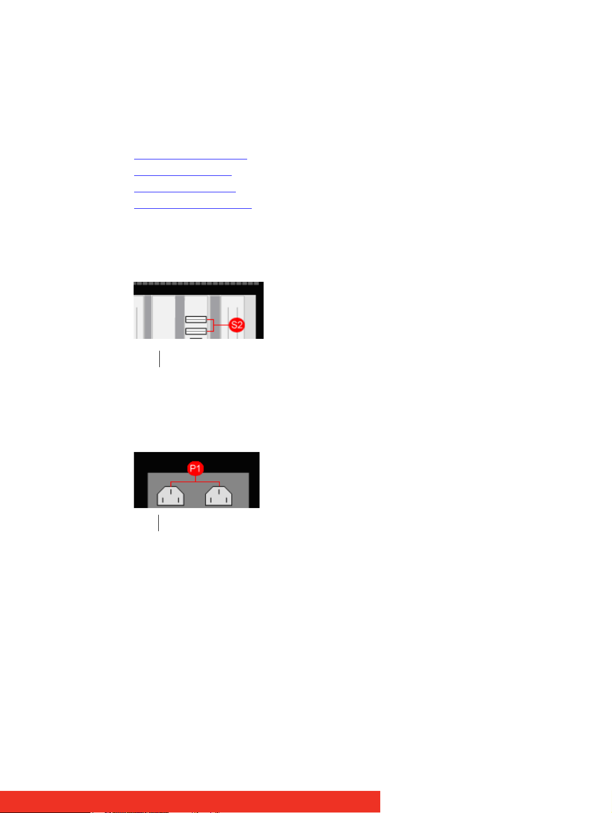
S2 USB Input connectors
Figure 1: USB input location
• Connect the USB Keyboard and Mouse into vacant USB connectors located on the rear
side of the unit.
P1 Power Connectors
Figure 2: Power connector location
• Connect both Power Cables to the chassis. Failure to connect both power cables will
result in an audible alarm being sounded when the system is switched on.
First use 11
Page 12
2.2.2 Connecting the output screens
CAUTION:
You should exercise great care when connecting all cables to the connectors.
If the pins are oriented correctly and the connector is pushed on squarely, the use of force is not required. Poor
handling may cause some pins to bend within the plug on the cable and this, in turn will cause damage to the
output socket and in some instances will cause irreparable damage to the Printed Circuit Board.
Such damage is not covered under warranty!
Control Screen
A Control Screen is a stand alone VGA output screen separate from the display wall. The
system is configured to boot up on the Control Screen. The Control Screen is configured as
the Primary Monitor in Windows® with the display wall as the Secondary Monitor.
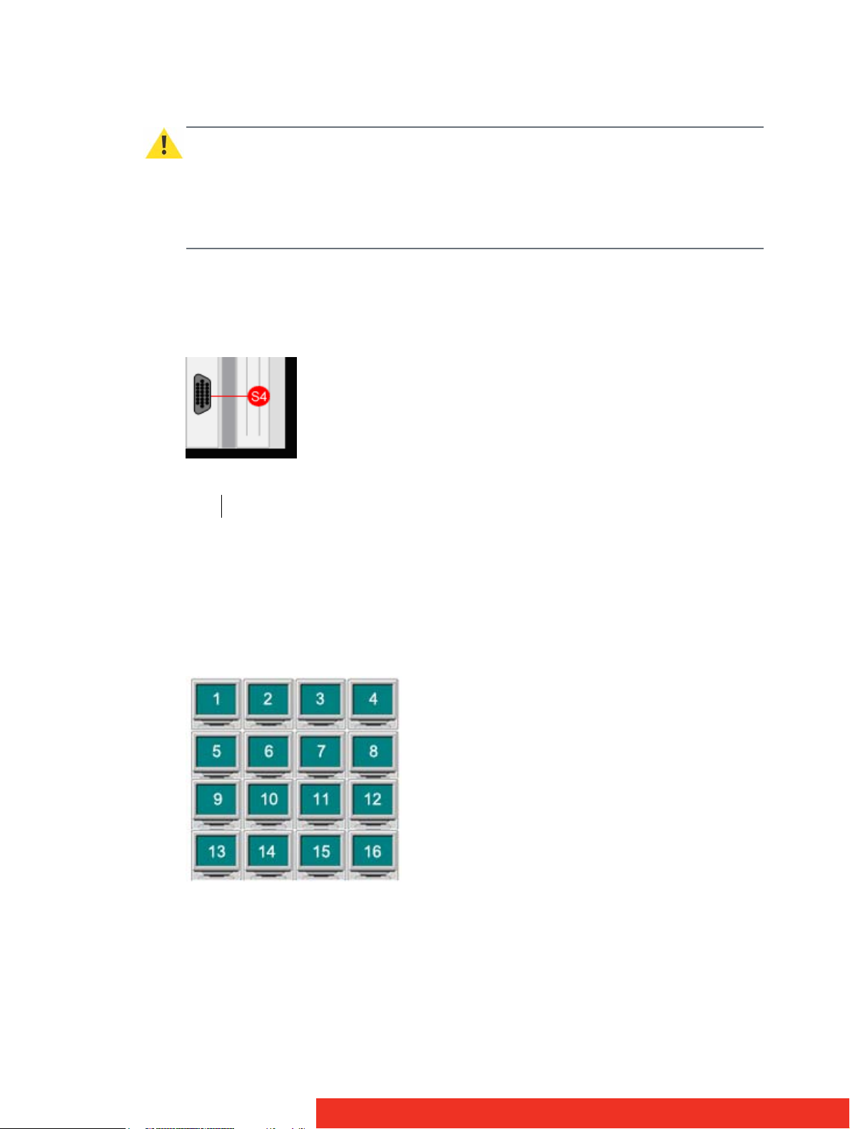
S4 VGA Output connector for the Control Screen
Figure 3: VGA output
• Connect your Control Screen to the VGA output of the ECU-100 unit using an analog VGA
Cable.
Display Wall
Figure 4: Screen arrangement (example)
12 First use
Page 13
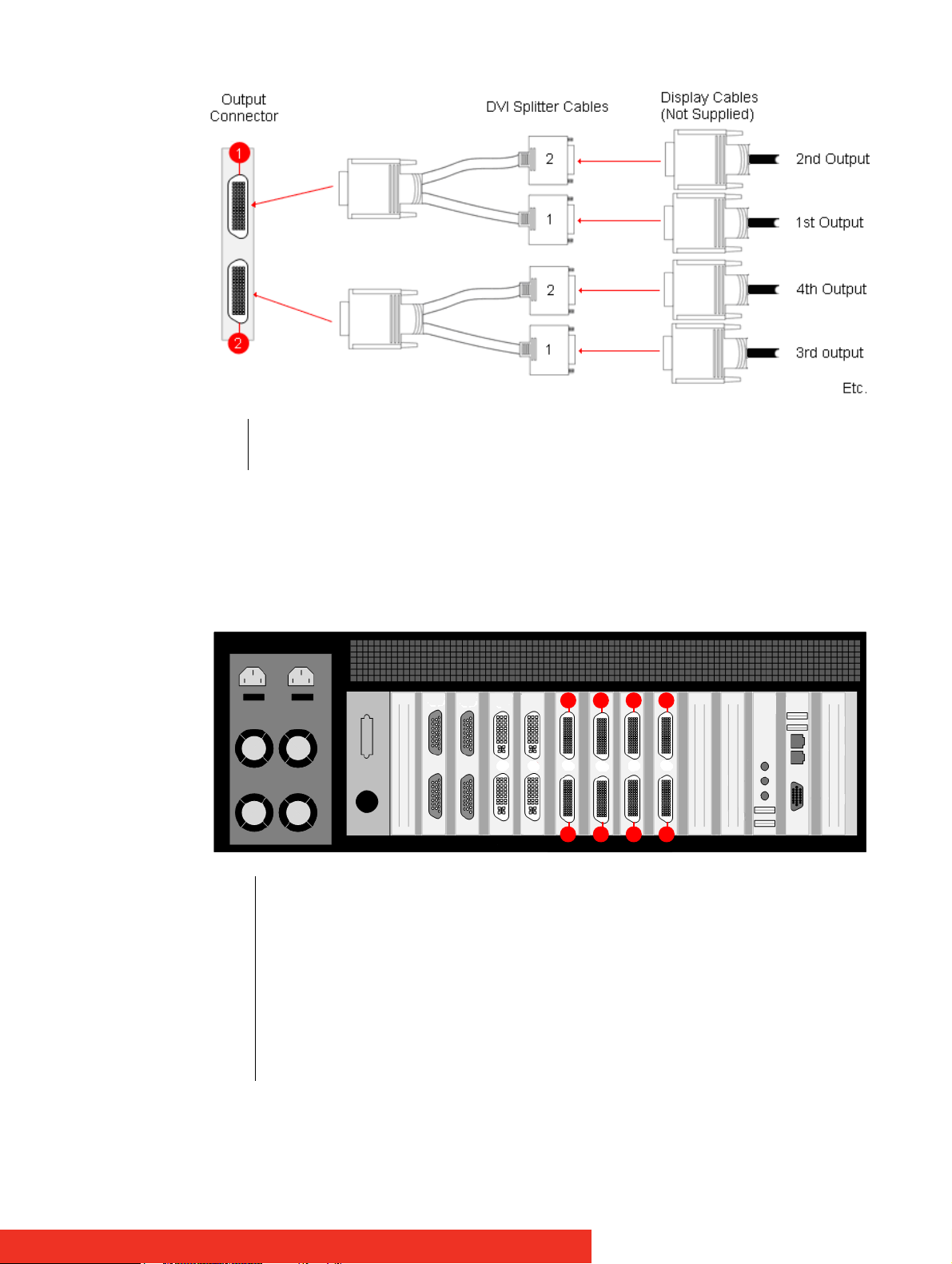
1 Output connector for screens 2 and 1
2 Output connector for screens 4 and 3
Figure 5: Monitor connection (display wall)
• Connect the monitors of the display wall to the output connectors using the DVI Splitter
Cables provided.
The example above illustrates the connection for screens 1 to 4 by making use of output connections 1 and 2.
357 1
468 2
1 Output connector for screens 1 and 2
2 Output connector for screens 3 and 4
3 Output connector for screens 5 and 6
4 Output connector for screens 7 and 8
5 Output connector for screens 9 and 10
6 Output connector for screens 11 and 12
7 Output connector for screens 13 and 14
8 Output connector for screens 15 and 16
Figure 6: Outputs location example of an ECU-100 GVD-1601604
First use 13
Page 14

2.2.3 Connecting the input sources
The system provides two types of input connectors:
• DVI-I –Type (See “Rear View” figures in paragraph “Overview of preconfigured ECU
hardware configurations”)
• D-Type (See “Rear View” figures in paragraph “Overview of preconfigured ECU hard-
ware configurations”)
DVI-I type
The DVI-I connectors support DVI, HDMI, Component and RGB (VGA) inputs using the
supplied adapters where required. See below, the different DVI-I connection possibilities:
• A DVI input is connected directly into the DVI-I connector which accepts DVI-D (digital)
or DVI-A (analog) inputs:
Figure 7: DVI to DVI-I connector
• An HDMI input is connected to the DVI-I connector using the supplied DVI-HDMI
Adapter:
Figure 8: HDMI to DVI-I connector
• A Component input is connected to the DVI-I connector using the supplied DVI-Component Adapter:
Figure 9: Component to DVI-I connector
14 First use
Page 15
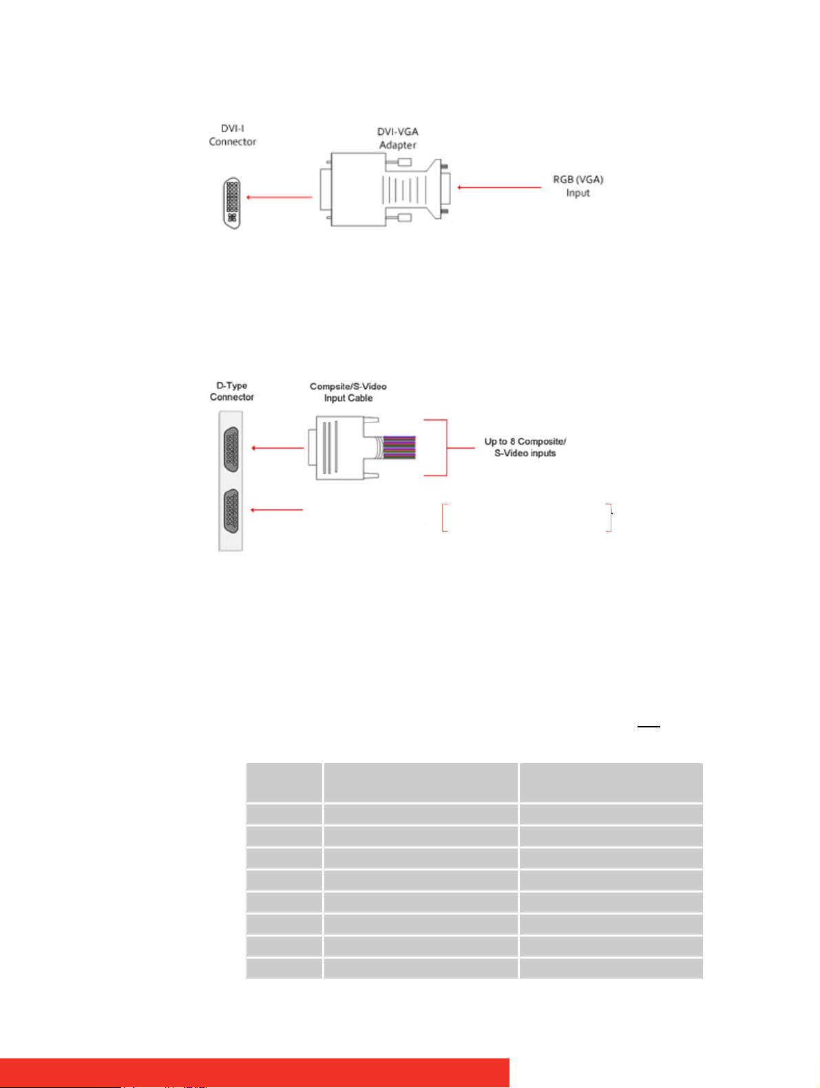
• An RGB (VGA) input is connected to the DVI-I connector using the supplied DVI-VGA
u
Adapter:
Figure 10: RGB (VGA) to DVI-I connector
D-Type
• Composite/S-Video inputs are connected to the D-Type Connector using the supplied
Composite/S-Video Cable:
Unused*
Unused*
*May be used for video passthrough, needs
* May be used for video Passthro
modified hardware settings.
needs modified hardware settings
Figure 11: Composite/S-Video to D-Type connector
• Use of Composite/S-Video Input cables
The Composite/S-Video input cable consists of 16 BNC sockets numbered 1-16, connected to a 26-way D-Type connector.
3 For Composite input signals only the first 8 BNC sockets are used.
3 To connect a S-video input, connect the Composite/S-Video Luma and Chroma sig-
nal as indicated in the table below:
Input Composite/S-Video Luma = BNC
Connector
1 1 9
2 2 10
3 3 11
4 4 12
5 5 13
6 6 14
7 7 15
8 8 16
S-Video Chroma = BNC Connector
First use 15
Page 16
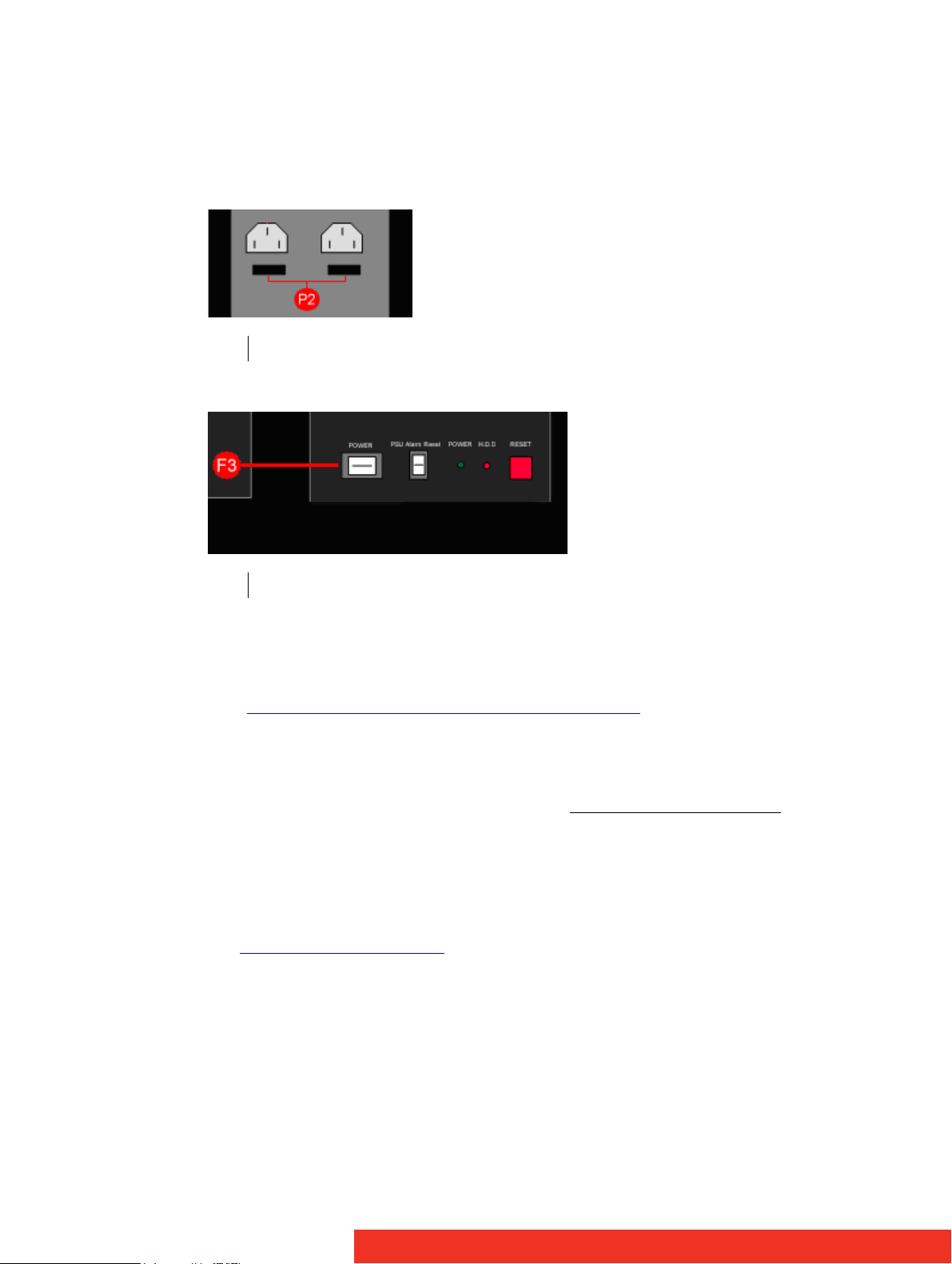
2.3 Switch on the system
2.3.1 Switching on
• Ensure that both Power Supply Units at the rear side are switched on.
P2 Main Power Switches at the rear side of the ECU-100
• Press and release the main power switch at the front side.
F3 Main power switch at the front side of the ECU-100
2.3.2 Setup procedure (only first use)
• The BIOS and boot messages will appear on the Control Screen that is plugged into the
VGA output socket of the ECU-100 (see S4 on figure on “Rear View” figures in paragraph
“Overview of preconfigured ECU hardware configurations
• When the system has booted the Windows® “Splash Screen” is displayed on the Control Screen.
• Complete the Windows® setup procedure to select language, user account details and
computer name. You will be prompted for the Operating System Product Key
located on the Operating System CD case in the Accessories pack.
• Once Windows® has been set up, the Control Screen and Display Wall will open into a
Windows® desktop.
• The ECU -100 has pre-configured factory settings for the wall layout and screen resolution. These settings can be changed using the Wall Configuration tab accessed from the
Display properties dialog box
.
”)
, this is
First use
Page 17
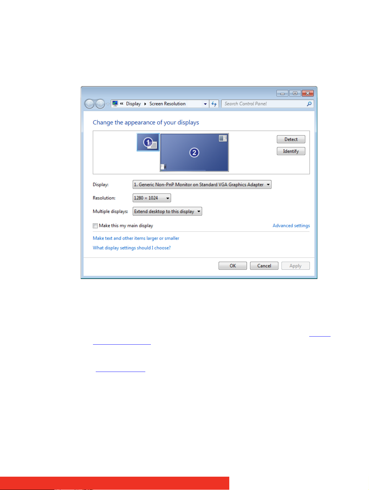
2.3.3 Changing pre-configured factory settings
• To change the pre-configured factory settings for the wall layout and screen resolution,
use the Wall Configuration tab.
• To access the Wall Configuration tab, right click on the desktop and select Screen Resolution, the following dialog is displayed:
Figure 12: Display properties dialog box
• This dialog shows the Control Screen as the Primary Monitor (1) and the display wall as
the Secondary Monitor (2).
• To access the Wall Configuration Properties tab, highlight the Secondary Monitor by
clicking once inside the box and then selecting Advanced settings (see figure “Display
properties dialog box”).
• If you wish to change the default factory settings, use the Wall Configuration tab to set
the number of screens, Screen Arrangement and Resolution per Screen (see figure
“Wall Configuration
”)
First use
Page 18
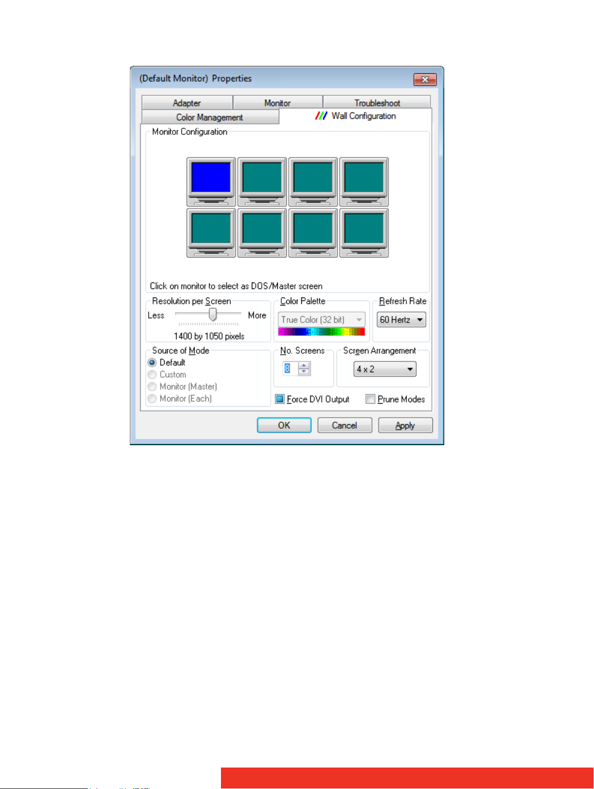
Figure 13: Wall Configuration
• In some instances, these changes may require a system re-start.
First use
Page 19
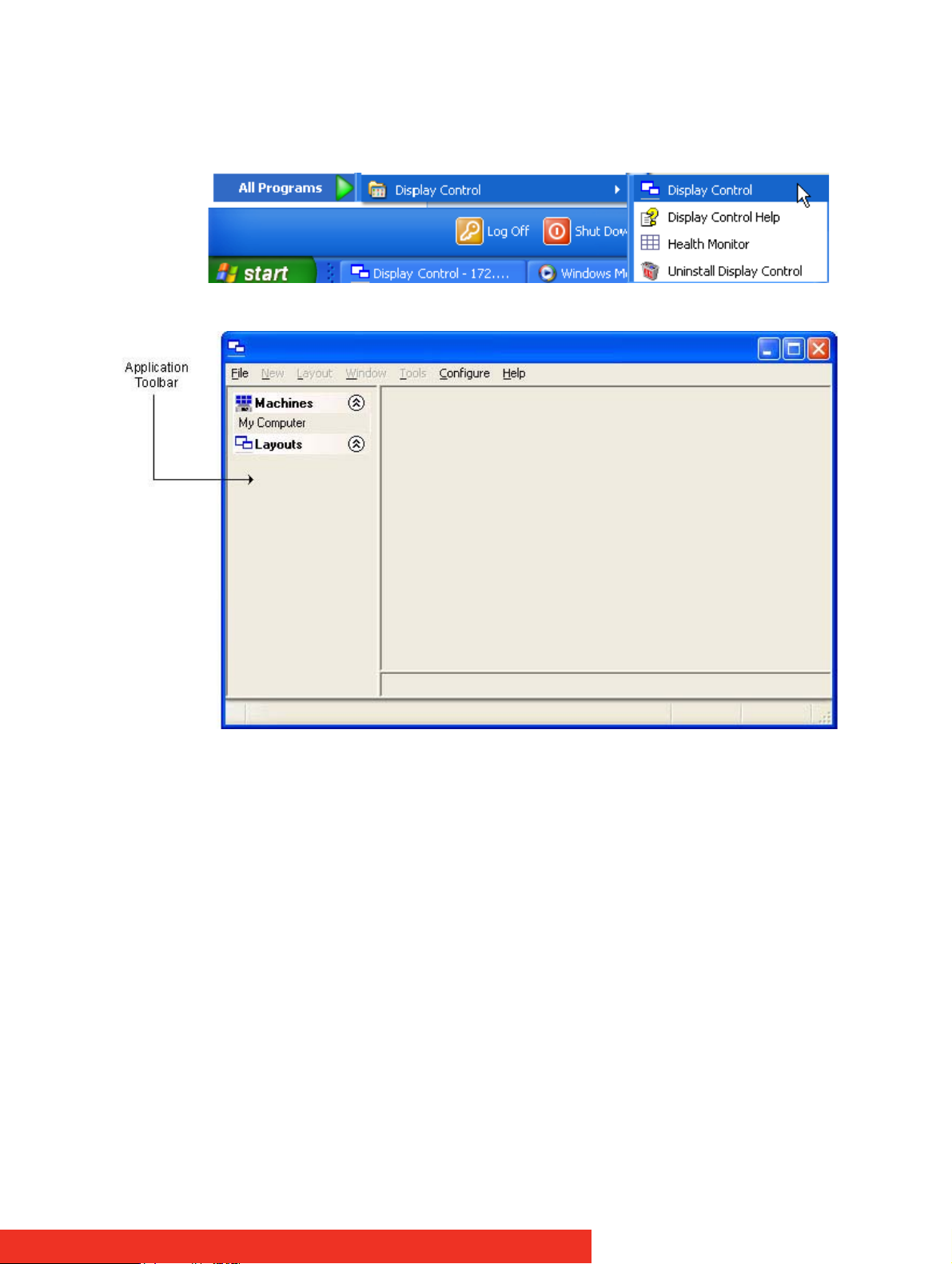
2.4 Launch Display Control
2.4.1 Starting up the Display Control application
Click on the Windows Start button and select All Programs/Display Control. From the Display
Control menu, select Display Control and the following dialog is displayed:
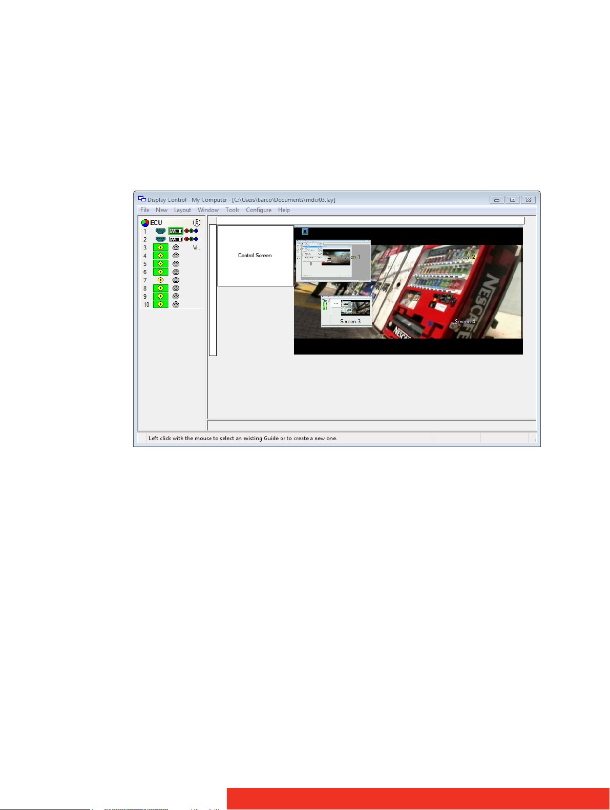
Figure 14: Display Control application
First use
Page 20
2.4.2 Make connection with the Display Control server
If the Display Control Application and Display Control server are installed on the same
machine then select Display Control-My Computer from the programs menu, alternatively,
double click My Computer in the Machines list on the Display Control Application Toolbar.
The Machines list shows the Display Control Servers that have previously been connected to.
The Layouts list shows the most recently used layout files. Double click to open the selected
file.
For more details on how to connect to the server, refer to “Connecting the application to
specific server”.
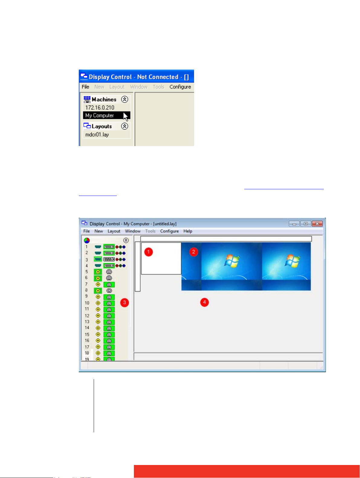
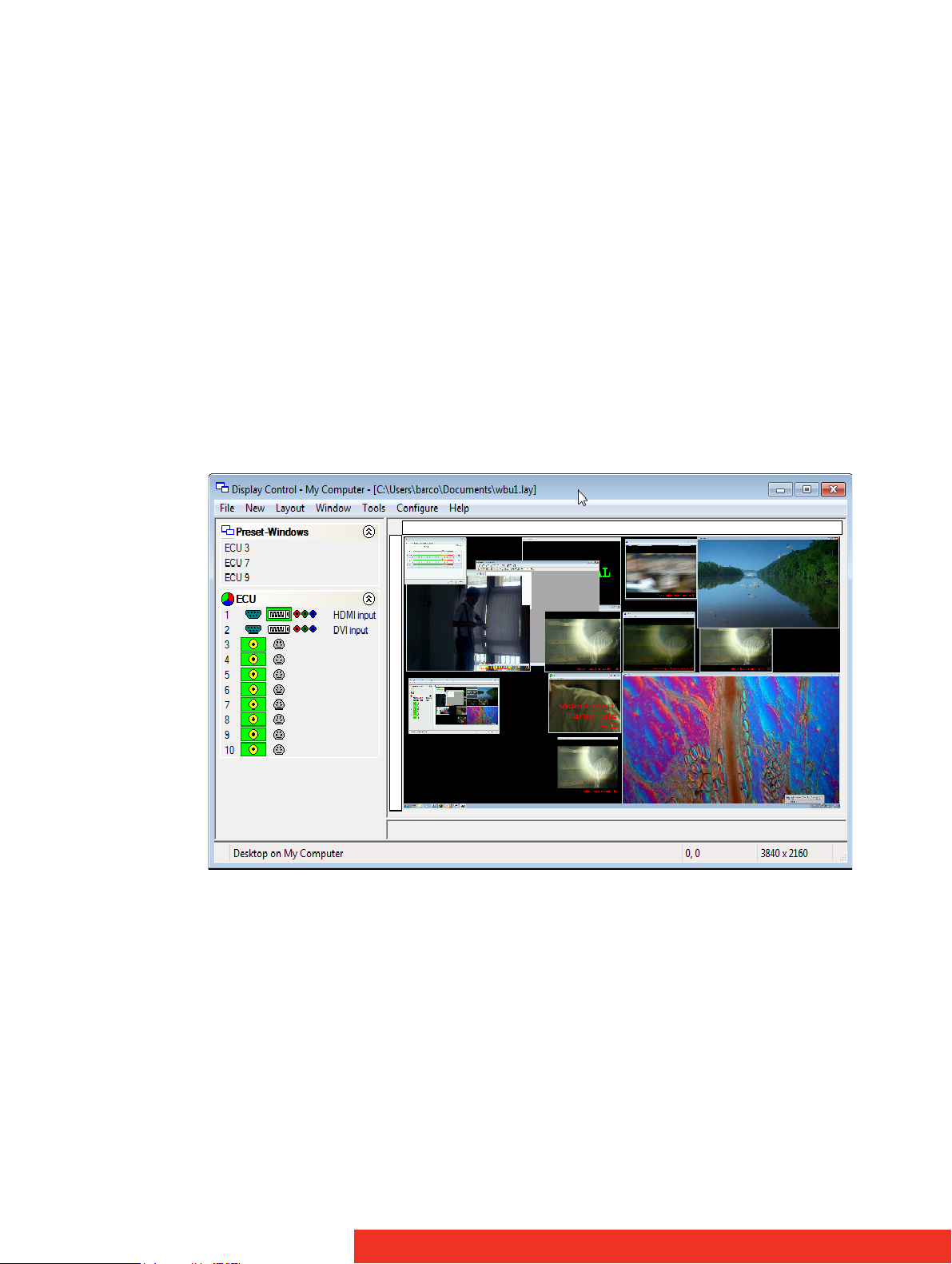
2.4.3 Application Window
1 Control Screen representation
2 Display Wall representation - Displays a snap-shot of the display wall including any input
sources currently displayed
3 Application toolbar - Displays the number and type of inputs available for display
4 Manipulation area - Area of the application around the desktop where windows can be
dragged allowing them to be manipulated without being displayed on the display wall
Figure 15: Display control application window
First use
Page 21
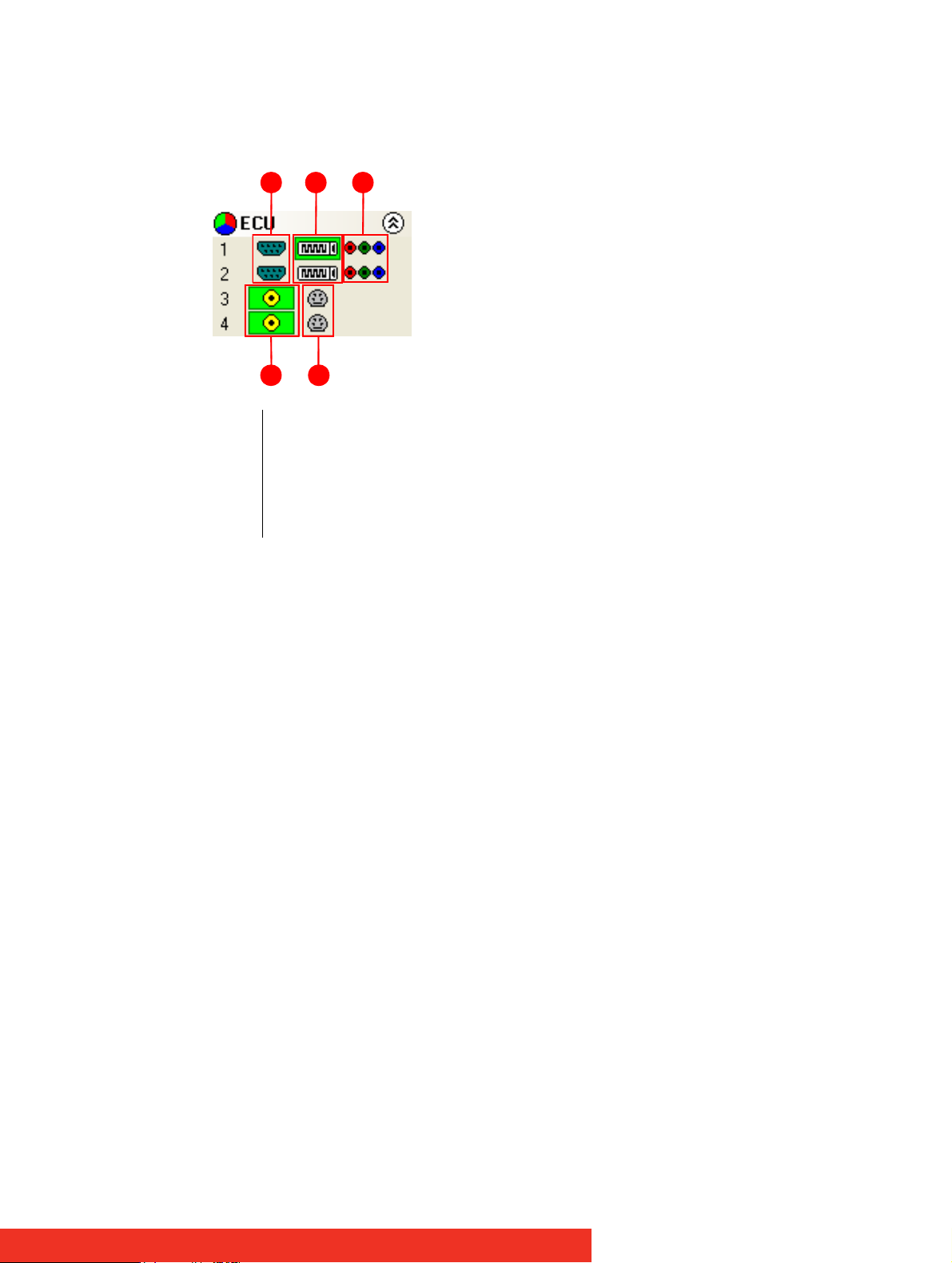
2.4.4 Toolbar
The icons displayed in the application toolbar identify which type of source is available to
each input.
1 Analog source
2 DVI source
3 Component source
4 Composite source
5 S-Video source
Figure 16: Application toolbar icons
1 2 3
4 5
If an icon is highlighted green, this indicates that an active input of that type is present.
For example in the figure above input 1 indicates that the DVI source is currently being
captured. For inputs 3 and 4, the composite input is captured.
First use
Page 22
2.5 Display inputs on the wall
2.5.1 Creating Windows
Once the connection to the server has been established then windows can be created for
display.
Windows can be created using the New menu or the application Toolbar.
•By using the New menu, the following windows can be created and displayed:
3 ECU - A ECU output can be displayed if a ECU-2DVI, ECU-8VID card is installed
3 Preset - A preset window can be displayed providing a ECU card is installed in the
system and one or more ECU windows have been saved as presets.
3 Application – Windows based applications can be opened and displayed eg. VNC
Viewer, Microsoft Powerpoint, DGCPlay.
3 Select Display Control from the Configure menu to capture the desktop and display
in the Display Control application window.
• Using the Display Control application Toolbar, you can select a particular device or input:
3 The application Toolbar displays a list of the type of windows that can be opened,
depending on the hardware you have installed in your machine. Use the drop
down menus to select the required inputs for display.
3 To open the required inputs, you can:
3 Select the required input using the cursor and drag to a preferred position on the
wall.
3 Double click on the required input and the window will open, positioned at the top
left of the display wall.
3 Open multiple inputs by pressing the shift key or Ctrl key and clicking the required
number of inputs with the mouse.
3 Using the Define Grid function, the windows can be placed in a specific position
using a 3-pixel width snap-to-grid functionality.
First use
Page 23

2.5.2 Moving Windows around the Display Wall
Setting up a video wall requires windows to be moved on the desktop. All types of window
can be moved in the same way.
Using the Window Properties
Windows can also be moved using the Window Properties
“Adapting Window menu options (Window menu)
the windows can be placed anywhere on the display wall.
Using the Mouse
Use the mouse to select the window in the Display Control application; by keeping the left
mouse button pressed, the window can be dragged to any preferred position on the wall.
Used conjunction with Grids and Guides, the window can be placed in an exact position.
Again, by using the mouse, right click over the window in the Display Control application
and select Move this allows you to move the window around the display wall without
depressing the mouse button. To release the window in a preferred position, click the left
mouse button.
”. Using the Position controls Top and Left
2.5.3 Changing Window Properties
The properties of a window can be changed using the Windows Properties, Input Settings
and On Screen Display Properties dialogs.
•The Window Properties
aspect ratio, the style, caption title and the window ID.
allow you to change the position of the window, the size and
dialog accessible via the
•The Input Settings
the Input, Cropping and Display setting controls.
•The On Screen Display properties
details of the on screen display.
allow you to change the appearance of a Display Control inputs using
allows you to configure the display type, text and font
First use
Page 24
3How to
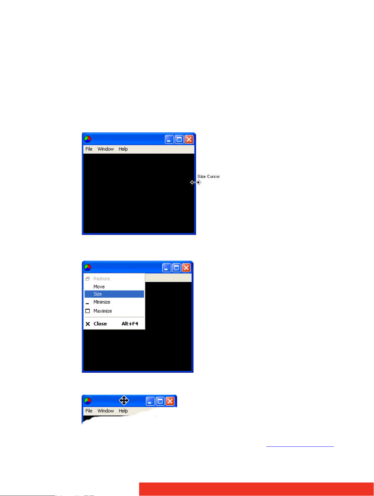
3.1 How to Re-size a Window
The Windows can be re-sized in various ways depending on the style setup on the Window
Properties sheet.
If the window has a border and title bar:
• Using the mouse, click on the top, bottom, left or right of the window border. The cursor
will change to a size cursor as shown below:
• Use the mouse to drag the border until the required size is achieved.
Press the Alt key and spacebar on the keyboard with the ECU Window active and a menu is
displayed as follows:
Select Size from the menu options and the cursor will change to a cross hair cursor and
displayed in the centre of the ECU window:
• Use the cursor keys to resize the window.
• Use the command line interface -Window as described in the Command Line Interface
paragraph.
How to
Page 25
• Access the Windows Properties dialog box by selecting Window Properties from the
Windows Menu. Use the Size controls to re-size the window.
NOTE:
The application can also be re-sized in the Display Control desktop representation.
If the window has no title bar or border:
• Use the command line interface -Window as described in the Command Line Interface
paragraph.
• Access the Windows Properties dialog box by selecting Window Properties
Windows Menu. Use the Size controls to re-size the ECU window.
NOTE:
The application can also be re-sized in the Display Control desktop representation.
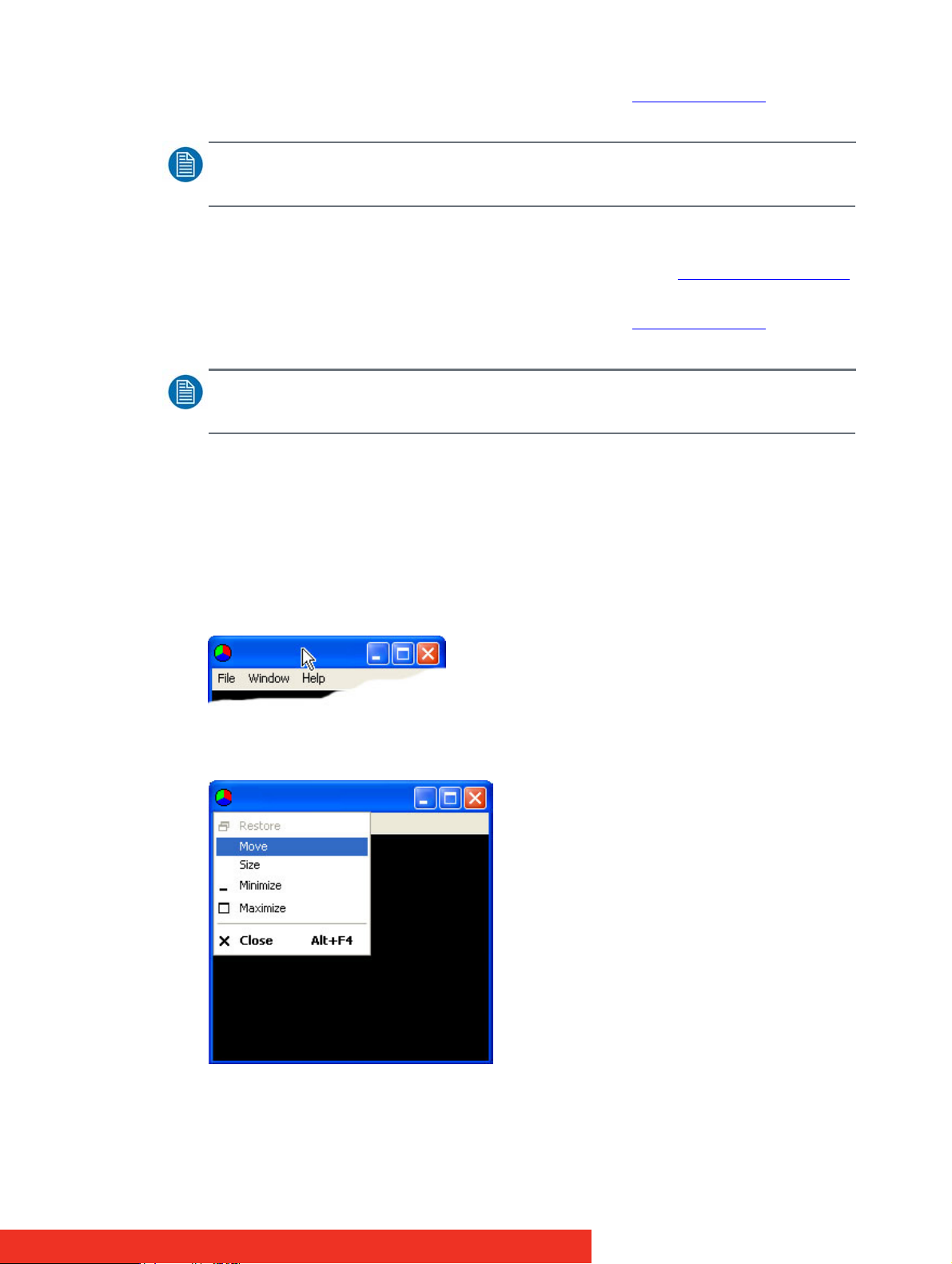
3.2 How to Re-position a Window
Windows can be re-positioned anywhere on the desktop. This can be achieved in a number
of ways depending on the style setup.
If the window has a border and title bar:
• Using the mouse, position the cursor on the title bar as shown below.
• Press and hold the left mouse button and drag the window to the required position.
•Press the Alt key and spacebar on the key board with the window active and a menu is
displayed as follows:
from the
Select Move from the menu options and the cursor will change to a cross hair cursor and
displayed in the centre of the window:
How to
Page 26

• Use the cursor keys to move the Window to the required position.
• Use the Command Line Interface -window as described in the Command Line Interface
paragraph.
• Access the Windows Properties dialog box by selecting Window Properties
Windows Menu. Use the Size controls to re-size the window.
3.3 How to Save/Load Wall Layouts
3.3.1 Saving Layouts
When your display wall has been configured i.e. all the required windows have been
opened and positioned, you may wish to save the layout.
Display Control allows you to save the layout as a
future use.
To save a layout, use the File menu on the Display Control Application and select Save or
Save As..
3.3.2 Loading Layout Files
To load a saved layout file:
With the Display Control application open, select the File menu and then Open… You will be
asked if you wish to save the changes you have made. Browse to the layout file you wish to
load and select Open. The layout will be opened and the windows positioned on the display
wall.
3.4 How to Save a Window as Preset
from the
.lay
file and store it on your machine for
Once a window has been configured and the window properties and cropping have been
set, the window can be saved as a preset. The presets are saved with a
in a folder called Preset Windows inside the directory where Display Control Server was
installed.
To save an ECU window as a preset, select a displayed ECU window and then select Save as
Preset from the Window menu. Alternatively, right click on the ECU window and select Save
as Preset.
.WCP
file extension
How to
Page 27

4 Display Control menu descriptions
4.1 Overview Menu Options
The Display Control Application has following menu options:
File
Managing layout files and connections (File menu)
New
Opening new Windows (New menu)
Layout
Creating grids, rulers and guides (Layout menu)
Window
Adapting Window menu options (Window menu)
Tools
Accessing other tools (Tools Menu)
Configure
Configuring types of window to be displayed (Configure Menu)
Help
Information about Display Control (Help Menu)
Display Control menu descriptions
Page 28
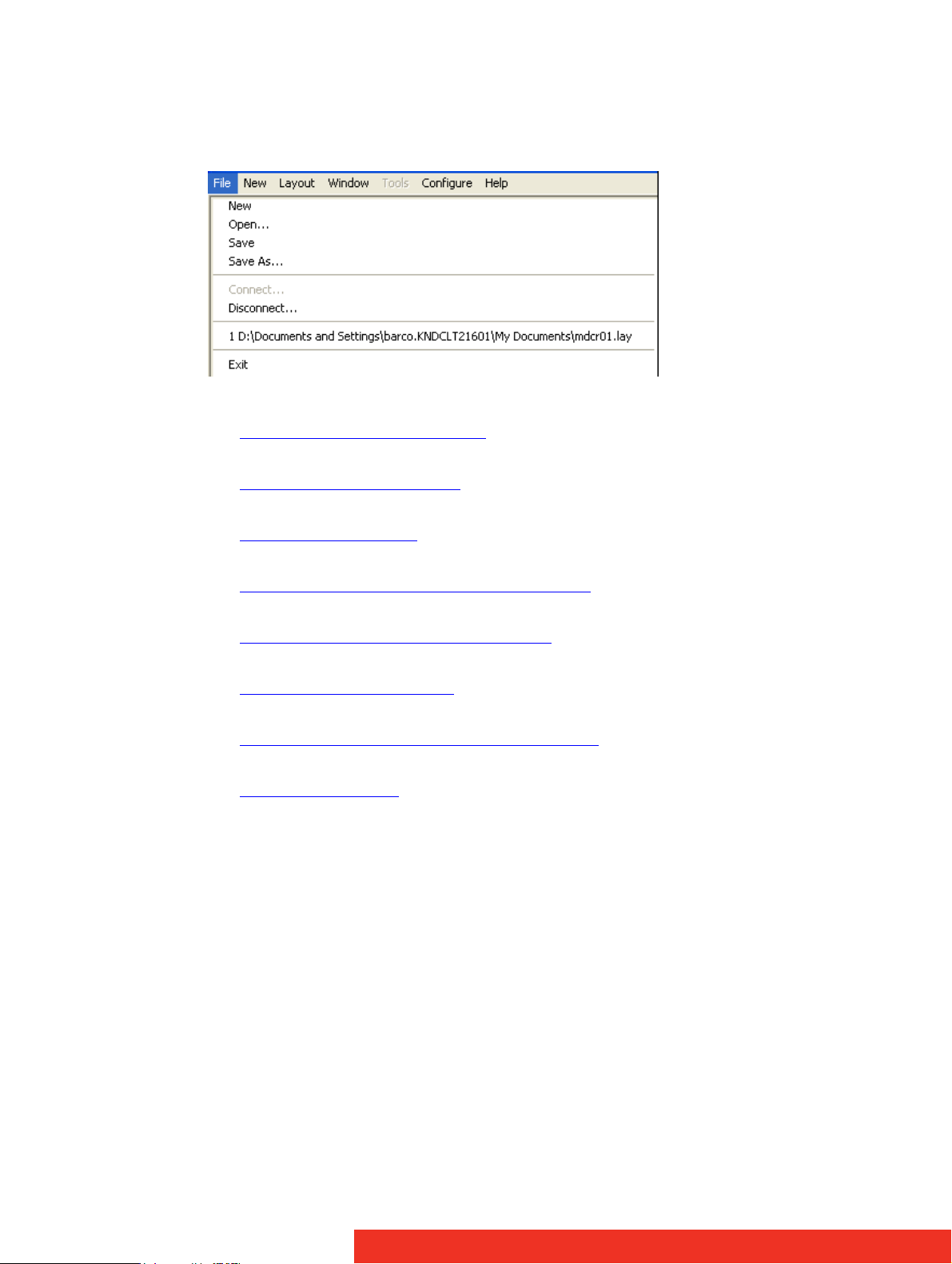
4.2 Managing layout files and connections (File menu)
The file menu allows you to manage layout files and connections
New
Opening a new (empty) layout file
Open
Opening an existing layout file
Save
Saving the current layout
Save As
Saving a layout with a specific name and location
Connect
Connecting the application to specific server
Disconnect
Closing the current connection
Most recently used files
Opening one of the most recently used layout files
Exit
Closing the application
28 Display Control menu descriptions
Page 29
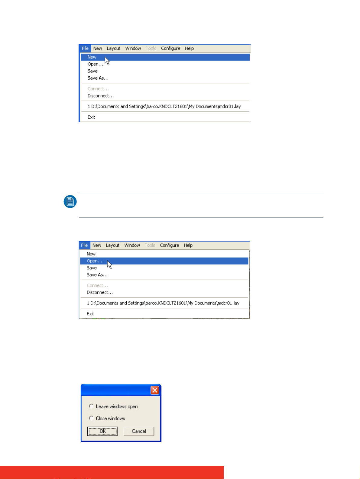
Opening a new (empty) layout file
When New is selected:
• A prompt is displayed asking if any changes to the current layout are to be saved.
• If changes are to be saved, click Yes and follow the steps detailed in Save/Save As
• If changes are not required to be saved click No
• The windows on the machine close.
• The image of the desktop from the machine will continue to be displayed.
NOTE:
The New option is only available when connected to a machine.
Opening an existing layout file
When Open is selected:
• A prompt is displayed asking if any changes are to be saved.
• Browse to the layout file to be opened.
When a layout file has been located and selected, the following takes place:
• If a current active connection is being used and the selected layout file is for a different
computer, the following dialog is displayed.
Display Control menu descriptions 29
Page 30
Select Cancel and the operation is terminated.
Select OK:
• If Close Windows is selected, all windows are closed and the connection is terminated.
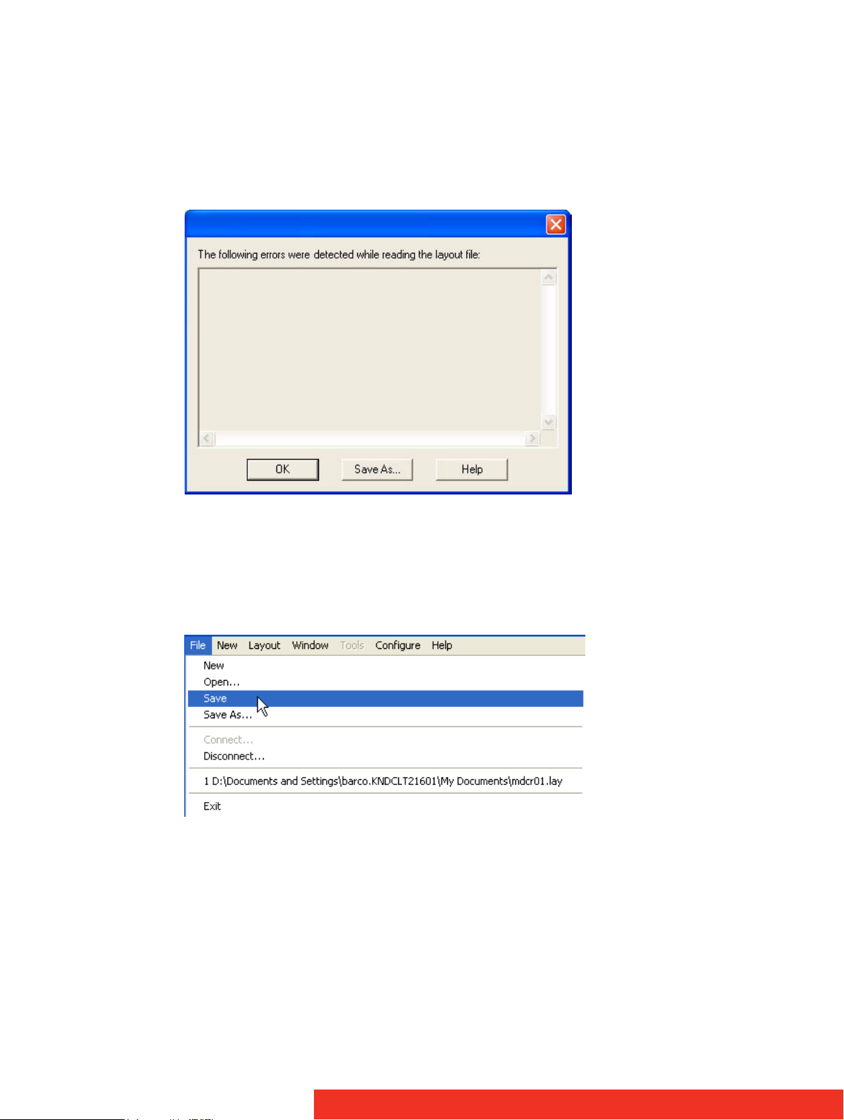
Previously Saved Layouts
When opening a previously saved layout the following dialog will be displayed should an
error occur:
The dialog displays details of any errors found by the application when opening a layout.
• Use the up/down arrows to scroll through the displayed text.
•Click on the Save As… button to save the information as a text file for later use or to
assist in support queries.
Saving the current layout
Select Save to save the current layout.
If the layout has not been previously saved, i.e. it is a new layout then the Save As dialog is
displayed.
Browse to the folder where the layout is to be saved, enter a File name and click on Save.
30 Display Control menu descriptions
Page 31

Saving a layout with a specific name and location
Select Save As to save a layout with a specific name to a particular location using the
displayed dialog.
NOTE:
Note: This function is only available if there is an active connection.
Connecting the application to specific server
The application can run on a local machine or an external client. Depending on this the
procedure to follow is different:
• Connecting the application using a local client
• Connecting the application using an external client
Display Control menu descriptions 31
Page 32

Connecting the application using a local client
• Select Connect… from the File menu and the following dialog will be displayed:
• Use this dialog to specify which machine is to be controlled using the Display Control
application:
3 Use the drop down arrow to display a list of the most recently selected machines;
the list will include My Computer to be used to connect to the machine where the
Display Control application is running.
• Use this dialog to specify the Windows settings:
3 Add existing windows to representation: Displays the open windows.
3 Close existing windows: Closes all Display Control managed windows.
• Click on OK to connect to the selected machine.
32 Display Control menu descriptions
Page 33

Connecting the application using an external client
An external client connection is needed when you would like to run the Display Control
Application from a different machine (= external client) over a network.
Therefore you will need to:
1. Install the Display Control Application on the external client by making the selection
below during the installation process (see application installation paragraph)
2. Connect the external client to the Display Control Application over the network. Therefore
proceed as follow:
• Select Connect… from the File menu and the following dialog is displayed:
• Use this dialog to specify which machine is to be controlled using the Display Control
application
3 The machine can be specified by name or by IP address.
3 Select Browse… to locate a machine on the local network.
• Use this dialog to specify the Windows settings:
3 Add existing windows to representation: Displays the open windows.
Display Control menu descriptions 33
Page 34

3 Close existing windows: Closes all Display Control managed windows.
• Click on OK to connect to the selected machine.
In case you connect to a machine that has been configured to authenticate connections:
• You will be required to provide a user name and password.
The user name and password must be for an account on the machine you are connecting to or on the domain if the machine is part of a domain.
34 Display Control menu descriptions
Page 35

• If the error message below is displayed one of the following problems has occurred:
3 The user name, the password or the machine/domain that you have entered are
not correct. Try entering the details again.
3 If the machine to which you are connecting is running Windows XP® Service Pack
2 and you have not entered a password, you will need to change your account so
that you have a password.
3 If the machine you are connecting to is running Windows XP® and it is not partici-
pating in a domain, you will need to change the Network Logon settings on the
machine. Network Authentication.
• You can create a shortcut on your desktop that specifies the machine and your user
name. When you double click on this shortcut, it will take you straight to the Logon dialog for you to enter your password.
Closing the current connection
This option is only available when a connection is active.
When Disconnect is selected, the following dialog is displayed:
The dialog offers two selections.
Leave windows open:
• Leaves open all windows that Display Control manages.
Close windows:
• Closes all windows that Display Control manages.
If any changes to the layout have been made, a Save prompt will be displayed.
Display Control menu descriptions 35
Page 36

Opening one of the most recently used layout files
Most Recently Used File List:
The File Menu contains a section where the six most recently used files are displayed, the
most recent at the top of the list. By selecting a particular file, the layout is re-loaded.
To select a file simply click on it or press the corresponding number on your keyboard.
If a file is selected that no longer exists then the file name will be automatically deleted.
Closing the application
Select Exit to close the application.
36 Display Control menu descriptions
Page 37

4.3 Opening new Windows (New menu)
The New menu displays options for each window category
Preset Windows
Opening a new Preset Window
ECU Window
Opening a new ECU Window
Run Application
Opening the Run Application dialog
Opening a new Preset Window
When Preset Window… is selected from the New Menu the following dialog is displayed:
The New Preset Windows option will not be available unless an ECU card is installed and
preset windows have been previously saved.
Use the drop down list to select the preferred Preset Window and click on OK. An ECU
window with the same window settings, input properties and on screen display that was
saved as a preset is created and displayed in the top left of the display.
Opening a new ECU Window
When ECU Window… is selected from the New Menu the following dialog is displayed:
Display Control menu descriptions 37
Page 38

Opening the Run Application dialog
When Run Application… is selected from the New menu and the following dialog is
displayed:
Application
The full path of the application executable must be specified.
You can select the application as follows:
• Use the drop down list to select a previously run application
•Click on the Browse button to select a new application
• Type in the full path of the application executable
Command line
Use the Command line edit box to specify parameters for the application. Many applications
accept the name of a file to be opened. For details of command line arguments, refer to
your application documentation.
Start in folder
The Start in folder is the folder in which the application is run.
If a Start in folder is not specified, the application will run in the folder in which it resides.
With Run Application, ECU-100 can launch any application. Unfortunately, each application
works in its own way so the exact outcome when you launch an application varies.
DGCPlay
DGCPlay is a utility that will play movie files including WMV, MPEG, and AVI depending on
the codecs installed on the system. Some media will require additional codecs not installed
as standard components of Windows.
To activate the DGCPlay application open Run Application from the New Menu by specifying
Dgcplay.exe as the target followed by the command line options separated by spaces. The
Dgcplay.exe will be located in the Display Control folder
Command Line Options
Nomenclature
Italic
- Information that you must supply.
38 Display Control menu descriptions
Page 39

Bold - Elements that you must type exactly as shown.
Ellipsis (...) - Parameter that can be repeated several times in a command line.
Between brackets ([]) - Optional items.
Between braces ({}) - Set of choices (separated by I) from which you must choose only one.
Courier font - Code or program output.
• -path=
media file path
• -Window=[
3 Change the position and size of the window.
3 All the values are optional but the commas must be used.
left
],[
top
],[
width
],[
height
]
• -WindowStyle= {BorderAndTitleBar|BorderOnly|NoBorderOrTitleBar}
• -repeat={Yes|No}
RealVNC Viewer
When you run RealVNC Viewer it will display a dialog asking you for a RealVNC server and
then display another dialog for a password for that server. You may not be able to respond
to these dialogs.
Once a connection has been made using RealVNC Viewer, you can save the connection
details to a configuration file. The configuration file can be specified on the command line
allowing RealVNC Viewer to run without displaying any dialogs.
Saving the Configuration File:
• Connect to the machine you wish to view with RealVNC Viewer.
• Click on the icon at left end of the title bar to display the menu.
• Select Save connection info as…
• Choose a file name and a folder and click on Save.
• You will be asked Do you want to save the password to this file? Click on Yes.
Using the Configuration File
In the Run Application dialog:
• In the Application box put the full path of the RealVNC viewer application.
For example:
C:\Program Files\RealVNC\vncviewer.exe
• In the Command Line box put /config followed by the full path of the configuration file.
For example:
/config "C:\Documents and Settings\User\ My Documents\file.vnc"
If the configuration file name or path contains spaces, enclose the path in quotes.
Microsoft PowerPoint®
To open a PowerPoint presentation as a slide show, use the following command line:
/s "C:\Documents and Settings\User\My Documents\presentation.ppt"
If the presentation file name or path contains spaces, enclose the path in quotes.
For a slide show to continue cycling through the slides, the PowerPoint window must be the
active window.
Only one PowerPoint application can be running at a time. If you try to start PowerPoint
while it is already running, the second PowerPoint sends a message to the first and then
exits.
Display Control menu descriptions 39
Page 40

When a layout file is opened, ECU-100 closes the windows and applications it is responsible
for and then creates the windows specified in the layout file. The windows and applications
are sent messages to close them. The PowerPoint application is run to create a PowerPoint
window.
If the existing PowerPoint application has not finished closing by the time ECU-100 tries to
open the new presentation, it is possible that a message to open a new PowerPoint
presentation and a message to close are sent to the existing PowerPoint application. The
result is that PowerPoint closes.
Display Control menu descriptions
Page 41

4.4 Creating grids, rulers and guides (Layout menu)
The Layout Menu enables you to create grids, rulers and guides in the Display Control
application.
Create Guide
Define Grid
Clear Guide
Clear all Guides
Create Guide
Select the Create Guide option and the following dialog is displayed:
Select the Orientation, either horizontal or vertical. Use the up/down arrows to adjust the
position of the guide i.e. the number of pixels from the top for vertical or left for horizontal
then click on OK. A guide is then created at the specified position.
You can also create a guide by clicking on one of the rulers.
Define Grid
Using the Define Grid option, a grid may be placed over the representation to assist in the
positioning of windows. The grid has a three pixel snap-to-grid functionality.
Display Control menu descriptions
Page 42

Using the up and down arrows, select the size of grid required.
Pixels
The grid can be defined by pixel size i.e. 150 x 150 pixels.
Divisions of a desktop
This option will divide the desktop into equal sized rectangles depending on the number of
divisions selected.
When the correct grid spacing has been selected, click on OK and a grid will be displayed in
the representation window.
To re-set a defined grid you must first select the Clear all Guides option otherwise the
previous grid will remain displayed.
Clear Guide
Right click on a guide in the ruler and select this option to clear the guide.
Clear all Guides
The Clear All Guides option removes all guides from the ECU-100 application window.
42 Display Control menu descriptions
Page 43

4.5 Adapting Window menu options (Window menu)
The options contained in the Window menu will not be activated unless windows are
displayed in the application.
Window Properties
Input Settings
On Screen Display
Split into Sub-Windows
Save As Preset Window
Restore
Move
Size
Minimise
Maximise
Close
Windows
NOTE:
The Window menu options will not be activated unless windows are displayed in the application.
Display Control menu descriptions 43
Page 44

Window Properties
Selecting Window Properties from the Window Menu will display a properties dialog box
relevant to the type of window currently active:
ECU Properties
Application Window Properties
44 Display Control menu descriptions
Page 45

ECU Properties
The ECU Window Properties sheet enables you to change the appearance of the ECU
window. When the required changes have been entered, click on Apply or OK for the
changes to take effect.
Select "Window Properties" with an ECU Window activated and the following dialog is
displayed.
The ECU Window Properties dialog has the following groups:
Position
Size
Aspect Ratio
Style
Cursor
Window ID
Caption
Invalid Input
Capture Format
Deinterlace
Capture Rate
Display Control menu descriptions 45
Page 46

Position
The position of the selected ECU window can be adjusted to suit your requirements using
the following controls:
Top and Left
Using the up and down arrows the selected ECU window can be positioned anywhere on
the desktop. The values are in pixels. The value Top = 0 and Left = 0 will position the ECU
window in the top left corner of the desktop. When the required values have been entered,
click on Apply and the changes will take effect.
Size
The size of the selected ECU window can be adjusted to suit your requirements using the
following controls:
Width and Height
The required width and height of the ECU window can be determined by using the up and
down arrows. The values are in pixels.
If Exclude borders is selected then the numbers in the "Width" and "Height" controls will not
include the borders, title bar and menu, only the active area within the application window.
Aspect Ratio
Maintain aspect ratio enables the data to be resized by changing the height; the width is
adjusted automatically so that the aspect ratio is maintained.
Do not maintain aspect ratio
Selecting Do not maintain aspect ratio enables the selected ECU window to be resized to
any rectangular configuration without constraints.
Maintain aspect ratio of source
Checking the Maintain aspect ratio of source button will preserve the aspect ratio of the
source captured by the ECU card in your machine.
If Cropping is not enabled on the Input Properties sheet then the "Width" and "Height"
values displayed in the Capture Settings group on the Input Properties sheet are used to
reflect the aspect ratio.
If Cropping is enabled then the Width and Height values in the cropping dialog are used as
the aspect ratio.
Maintain aspect ratio
46 Display Control menu descriptions
Page 47

If you select Maintain aspect ratio you can specify the aspect ratio you would like the ECU
window to have.
When the required values have been entered, click on Apply or OK and the changes will
take effect.
Style
The appearance of the ECU window can be changed to suit your particular requirements:
Border and title bar
Select this option to display the border and title bar of the active ECU window.
Border only
Select this option to display the ECU window with just a border. In this state, the ECU
window may still be resized using the borders.
No border or title bar
Select this option to display the source only. The ECU window can only be resized by using
the Size and Position function as described above. See "How To Re-size a Window".
Click on Apply or OK and the style chosen will take effect.
Show menu bar
Select to display the ECU window menu bar.
If you want to restore the menu bar you can access the Window Properties sheet by right
clicking in the ECU window and selecting Window Properties from the menu. Show menu
bar can then be selected.
Always on top
If the Always on top option is selected the windows will be displayed in front of all others
windows that are not always on top.
Cursor
Always Show
Always shows the cursor in the client area of the window.
Always Hide
Always hides the cursor in the client area of the window.
Hide when window active
Only hides the cursor in the client area of an active window. If the window is divided using
the split screen function, the cursor is visible in all sub-windows that are not active.
NOTE:
Cursor hiding only works when cursor is stationary over the ECU window.
Display Control menu descriptions 47
Page 48

Window ID
Use the up/down arrows to select a required Window ID. The Window ID identifies a
window enabling it to be modified from the command line. See Command Line Interface
dialog.
Caption
The Caption edit box can be used to change the caption in the title bar of the selected ECU
window.
Variables
The Variables function is a means of displaying a changeable value in the title bar.
Invalid Input
Should the source become disconnected, switched off, changed to a mode that is out of
range of the ECU capture card and no frames are being captured you have the option to:
Display message after - milliseconds
If you want to be made aware that the source cannot be captured then you can display a
message informing you that no signal is being received for example:
Capture Format
This option allows you select the pixel format you wish use. The Capture Format has an
effect on the performance of a system.
Automatic
Select Automatic and the data is captured in the same pixel depth as the desktop.
5-5-5 or 5-6-5
If either of these options is selected, the format will be captured at 16 bit. For most systems
this is by far the most efficient
48 Display Control menu descriptions
Page 49

8-8-8
If this option is selected then the format will be captured at 32 bit.
Deinterlace
Deinterlace is only available if an interlaced source is being captured.
Bob
Bob is more suited to captures displaying motion and offers higher frames per second.
Weave
Weave is more suited for images captured with little or no motion; any change in the
captured image will cause artifacts known as tearing.
None
Only a single field will be displayed.
Capture Rate
The Capture Rate control gives a degree of control over the capture rate by enabling you to
select the percentage of frames to be captured from the source. 100% is the default capture
rate.
For example:
If the refresh rate is 60Hz, selecting a capture at 15% will capture a maximum of 9 frames
per second (FPS), selecting 10% will capture a maximum of 6 FPS.
If a capture rate of 100% is selected, an attempt is made to capture as many frames as
possible. In this instance, the capture may be directed to the buffer at the same time as the
buffer is being displayed. This can sometimes cause a single horizontal tear on moving
images in the ECU application window.
A different capture rate can be selected for when the ECU window is inactive. This enables
system resources to be managed more efficiently. Reducing the percentage of frames
captured for an inactive window will free more system resources for other tasks.
Select
Capture at____ when window is inactive
and using the drop down menu select the
required capture rate for when the window is inactive.
Display Control menu descriptions 49
Page 50

Application Window Properties
Select Window Properties... with an Application window activated and the following dialog
is displayed.
There are various ways to access the Window Properties page, select from the following:
• In the ECU-100 application, with the window active, open the Window menu and select
Window Properties… from the list of options.
• In the displayed window, open the Window menu and select Window Properties…
• In the ECU-100 application, place the cursor over the representation of the Window and
click the right mouse button. Select Window Properties… from the list of options.
• Place the cursor over the active Window on the desktop, click the right mouse button
and select Window Properties… from the list of options.
• In the ECU-100 application, if a window has been minimized an application icon will be
displayed in the application mini bar. Place the cursor over the application icon and
right click the mouse button. Select Window Properties… from the list of options.
50 Display Control menu descriptions
Page 51

When this dialog is displayed, the application window is disabled, preventing other users
from modifying or closing it.
Size and Position
The size and position of the window can be entered manually. The position values are
relative to the top left corner of the desktop.
Style
The Style options can be used to alter the border style of the window, for example, select
the Border only option and the title bar will not be displayed, select the No border or title
bar and the application only is displayed.
The Show menu bar option allows you to hide the menu bar.
If the Always on top option is selected the window is displayed in front of all others
windows that are not always on top.
Display Control menu descriptions 51
Page 52

Caption
The caption box displays the title of the application window.
52 Display Control menu descriptions
Page 53

Input Settings
Selecting Input Settings from the Windows menu will display the Input Settings dialog
relevant to the type of window currently active:
ECU Input Settings
Application Input Settings
Display Control menu descriptions 53
Page 54

ECU Input Settings
Accessing the ECU Input Settings.
There are various ways to access the Application Input Settings page, select from the
following:
• In the Display Control application, with the Application window active, open the Window menu and select Input Settings… from the list of options.
• In the Display Control application, place the cursor over the representation of the Application Window and click the right mouse button. Select Input Settings… from the list of
options.
• In the Display Control application, if a window has been minimized an application icon
will be displayed in the application mini bar. Place the cursor over the application icon
and right click the mouse button. Select Input Settings… from the list of options.
The Input Settings sheet allows you to control how the source is captured and displayed in
the ECU window. All the controls on this sheet are interactive; therefore, any changes made
are shown when the next frame of data is displayed in the ECU window.
There are two types of Input Setting sheet in the ECU application; RGB/DVI capture and
Video capture.
54 Display Control menu descriptions
Page 55

RGB/DVI
Video Capture
The ECU Input Settings sheet has the following groups:
Source
Capture Settings
Display Control menu descriptions 55
Page 56

Resolution and Refresh
Cropping
Video Adjustments
Colour Adjustments
Source
The Source control specifies which source is displayed in the window. Select the input from
the drop down list. You can give the inputs meaningful labels in the Configure ECU dialog.
When you change inputs, the Capture Settings controls may change.
See the ECU User Manual for information on the input connections.
Capture Settings
Share these capture settings across all inputs.
With Share these capture settings across all inputs selected, the changes you make to the
capture settings controls will be shared with other inputs of the same type. The capture
settings will also be saved automatically so that the next time a ECU window is created, the
capture settings can be used.
Use these capture settings with this input only.
With Use these capture settings with this input only selected, the changes you make to the
capture settings controls will be applied to this ECU window only.
Reset
The Reset button will discard any changes you have made to the capture settings and
display the source with default settings.
Resolution and Refresh
Width
The width specifies the horizontal resolution of the source.
Height
The height specifies the vertical resolution of the source.
Vertical Refresh
The Vertical Refresh specifies the vertical refresh rate of the captured source.
Cropping
56 Display Control menu descriptions
Page 57

The cropping controls allow you to display a specific area of the signal within the ECU
window. The co-ordinates are relative to the start position defined by Horizontal Position
and Vertical Position.
For a single ECU window, a different cropping area is remembered for each video mode. If
the source being captured changes, a different cropping area is used.
Video Adjustments
RGB/DVI
Composite/S-Video
The Video Adjustment controls describe the video timings being used to capture the source.
Ideally, the values should match the video timings of the source.
Horizontal Position
The Horizontal position specifies the offset, in pixels, from the end of the horizontal sync to
the start of the active video.
Horizontal Size
The Horizontal size specifies the total number of pixels used to sample lines within the
source. This includes the active portion of video and blanking.
Phase
If the captured image is noisy, it may be that the signal is being sampled close to the
transition between pixels. The Phase control allows you alter the point at which the signal is
sampled. You can think of it as a fine horizontal position control. This control is not available
when composite or S-Video is being captured.
Vertical Position
The Vertical position specifies the offset, in lines, from the end of the vertical sync to the
start of the active video. This control is not available when composite or S-Video is being
captured.
Display Control menu descriptions 57
Page 58

Black Level
At the beginning of each line the source must be sampled to measure the black level. This
sample is used as a reference for determining the brightness of the pixels on the line. The
Black Level control allows you to specify the position at which the black level of the signal is
sampled. This control is not available when composite or S-Video is being captured.
NOTE:
The Video Adjustment settings are not available when a DVI source is being captured.
Video Standard
Select the required video standard from those available in the drop down menu.
Colour Adjustments
Brightness
The Brightness control allows you brighten or darken the capture.
Contrast
The Contrast control allows you to alter the difference between the light parts of the capture
and the dark parts of the capture.
Saturation
The Saturation control allows you to increase or decrease the saturation
Hue
The Hue control allows you to increase or decrease the hue. This is only available for NTSC
captures.
Click on the Colour Balance… button to change the colour balance for the specified input
connector. This function is only available when capturing analog sources.
NOTE:
All colour controls are the only ones available when a DVI source is being captured. The Red, Green and Blue
controls are for RGB analog only.
58 Display Control menu descriptions
Page 59

Colour Balance
The Colour Balance dialog allows you to change the colour balance for an input connector.
All controls in this dialog box are interactive so the changes you make will be seen when
the next frame of data is displayed in the ECU window.
All Colours
The Brightness and Contrast controls alter the settings for all Colours. These are the same as
the Brightness and Contrast controls in the ECU Input Settings sheet.
Red
The red controls allow the brightness and contrast of the red part of the ECU signal to be
adjusted a small amount relative to the over all brightness and contrast settings.
Green
The green controls allow the brightness and contrast of the green part of the ECU signal to
be adjusted a small amount relative to the over all brightness and contrast settings.
Blue
The blue controls allow the brightness and contrast of the blue part of the ECU signal to be
adjusted a small amount relative to the over all brightness and contrast settings.
Reset
The Reset button will set all the values to the default settings.
Display Control menu descriptions 59
Page 60

Application Input Settings
Accessing Application Input Settings
There are various ways to access the Application Input Settings page, select from the
following:
• In the Display Control application, with the Application window active, open the Window menu and select Input Settings… from the list of options.
• In the Display Control application, place the cursor over the representation of the Application Window and click the right mouse button. Select Input Settings… from the list of
options.
• In the Display Control application, if a window has been minimized an application icon
will be displayed in the application mini bar. Place the cursor over the application icon
and right click the mouse button. Select Input Settings… from the list of options.
Select Input Settings with an Application window activated and the following dialog is
displayed.
60 Display Control menu descriptions
Page 61

When this dialog is displayed, the application window is disabled preventing other users
from modifying or closing it.
The dialog displays the application currently selected and the command line arguments (if
any) associated with the application.
Display Control menu descriptions 61
Page 62

On Screen Display
Selecting On Screen Display from the Window Menu will display the screen display dialog
relevant to the type of window currently active:
ECU On Screen Display Properties
Accessing ECU On Screen Display
.
There are various ways to access the On Screen Display (OSD) properties sheet, select from
the following:
• In the Display Control application, with a window active, open the Window menu and
select On Screen Display… from the list of options.
• In the displayed window, open the Window menu and select On Screen Display…
• In the Display Control application, place the cursor over the representation of the window and click the right mouse button. Select On Screen Display… from the list of
options.
• Place the cursor over the active window on the desktop, click the right mouse button
and select On Screen Display… from the list of options.
In the Display Control application, if a window has been minimized an application icon will
be displayed in the application mini bar. Place the cursor over the application icon and right
click the mouse button. Select On Screen Display… from the list of options.
62 Display Control menu descriptions
Page 63

The On Screen Display sheet allows you to configure the On Screen Display in the ECU
window. Any changes made to the settings on the On Screen Display sheet take effect
immediately.
If a ECU window is opened without a source connected, any text entered in the On Screen
Display dialog is not displayed until a source has been connected.
Display Type
No on screen display
Disables the OSD function.
Simple Text
Select to insert the required text into the Simple Text edit box. When the Simple text option
is selected, the Simple Text, Background, Margins and Alignment groups are displayed on
the OSD sheet.
From File
Not yet functional.
Scaling
Display Control menu descriptions 63
Page 64

Fixed size
When Fixed size is selected, the OSD is displayed at the same size regardless of the size of
the window.
Scale with window
When Scale with window is selected, the OSD is scaled up or down according to the size of
the window.
Simple Text
To enter text for the OSD simply type the required message in the Simple Text edit box.
Variables
The Variables function is a means of displaying a changeable value in the title bar.
Line wrapping
With Line wrapping switched on, if a line of text does not fit between the margins, line
breaks are inserted between words to produce shorter lines.
If Line wrapping is switched off, the text is displayed with the same spaces and line breaks
as it has been entered.
Font
Select Font and the following dialog is displayed:
Using the groups available, the characteristics of the font can be determined.
64 Display Control menu descriptions
Page 65

Background
Transparent
When Transparent is selected, the ECU capture in the area behind the text is visible.
Opaque
When Opaque is selected, the area behind the text is displayed in a chosen colour. A range
of colours are available by selecting Colour…
Margins
The margins define the area in which OSD is displayed.
If Scale with window is selected, the margins are measured in pixels of the source. If Fixed
size is selected, the margins are measured in pixels of the interior of the ECU window.
Any part of the OSD that falls outside the margins is not displayed.
Alignment
The alignment controls allow you to position the OSD within the margins.
Vertical
If you select Top, the top edge of the OSD will be displayed against the top margin.
If you select Centre, the centre of the OSD will be positioned half way between the top and
bottom margins.
If you select Bottom, the bottom edge of the OSD will be displayed against the bottom
margin.
Horizontal
If you select Left, the left edge of the OSD will be positioned against the left margin and
each of the individual lines will be left aligned.
If you select Centre, the centre of the OSD will be positioned half way between the left and
right margins and each of the individual lines will be centered.
If you select Right, the right edge of the OSD will be positioned against the right margin and
each of the individual lines will be right aligned.
Display Control menu descriptions 65
Page 66

Split into Sub-Windows
Accessing the Split into Sub-Windows dialog
There are various ways to access the Split into Sub Windows page, select from the
following:
• In the Display Control application, with an ECU window active, open the Window menu
and select Split into Sub-Windows.
• In the displayed ECU window, open the Window menu and select Split into Sub-Windows
• In the Display Control application, place the cursor over the representation of the ECU
window and click the right mouse button. Select Split into Sub-Windows from the list of
options.
• Place the cursor over the active ECU window on the desktop, click the right mouse button and select Split into Sub-Windows from the list of options.
The Split into Sub-Windows function only applies to ECU windows
Select Split into Sub-Windows and the following dialog is displayed:
66 Display Control menu descriptions
Page 67

The Split into Sub-Windows dialog is used to divide an active ECU window into subwindows. Each sub-window will display a cropped portion of the image that was shown in
the original window. The sub-windows will all be the same size and will occupy the same
total screen size and position as the window that is being split.
NOTE:
Once a window has been split the sub-windows will replace the original window and the split operation cannot
be undone.
Cropping restrictions may result in pixel loss for certain input resolutions and split
topologies.
The Split into Sub-Windows dialog has the following groups:
Sub-Window Topology
Split Windows
Split Window Options
Preview
Sub-Window Topology
The Sub-Windows topology group allows you to select the number of sub-windows that will
be created when the window is split. The number of sub-windows must be between two
and sixteen inclusive. However, the maximum number of split-windows may be limited by
Display Control menu descriptions 67
Page 68

the size of the window being split. The minimum sub-window size is 160x120 pixels.
Therefore, in order to split a window into sixteen sub-windows then the size of the window
being split must be at least 640x480 pixels. Use the horizontal and vertical window edit
boxes to select the desired sub-window topology.
Split Windows
The Split-Windows group allows you to select the caption names and preset filenames for
the sub-windows. The preset filenames are used to save each sub-window as an individual
template called a preset. These presets can subsequently be used in Display Control to
create an instance of the sub-window.
Window Number
The Window number drop down list allows you to select a specific sub-window. The Caption
and Preset filename edit boxes may then be used to set the desired caption and filename
for the respective sub-window. When All is selected then any changes to the Caption and
Preset filename edit boxes will be applied to all of the sub-windows.
Caption
The Caption edit box is used to change the name in the title bar of the selected ECU subwindow(s).
Preset filenames
The Preset filename edit box allows you to select the filename (without suffix) that will be
used to save the preset for the specific sub-window selected in Window number. The preset
filenames must be unique with respect to each other. If the input variable is inserted into
the Preset filename for a specific sub-window then it will be substituted with the name of
the input itself before the preset is saved.
The Preset filename edit box will only be enabled if the Save as preset-windows checkbox
is selected.
Split Window Options
The Split Window Options allow you to select whether existing ECU windows are closed or
saved as presets when the window has been split.
Close existing input windows
If selected, other displayed ECU windows from the same input will automatically close
when the window is split. ECU windows from other inputs are not affected.
By default, Close existing input windows is not selected.
Save as preset-windows
If selected, then the sub-windows will be saved as Display Control preset files when the
window is split.
By default, Save as preset-window is selected.
68 Display Control menu descriptions
Page 69

Once all options have been selected, click OK to split into sub-windows.
Preview
The preview frame displays an image showing how the window will look after it is split into
sub-windows.
Display Control menu descriptions 69
Page 70

Save As Preset Window
Once a window has been configured and the window properties and cropping have been
.WCP
set, the window can be saved as a preset. The presets are saved with a
file extension
in a folder called Preset Windows inside the directory where Display Control Server was
installed.
To save an ECU window as a preset, select a displayed ECU window and then select Save as
Preset from the Window menu. Alternatively, right click on the ECU window and select Save
as Preset.
70 Display Control menu descriptions
Page 71

Restore
This option restores the current window. This option is only available when the window is
minimized or maximized.
Display Control menu descriptions 71
Page 72

Move
The selected window can be moved using the keyboard interface of the representation. This
option is not available when the window is minimized or maximized.
72 Display Control menu descriptions
Page 73

Size
The size of the selected window can be changed using the keyboard interface of the
representation. This option is not available when the window is minimized or maximized.
Display Control menu descriptions 73
Page 74

Minimise
Selecting this option minimises the selected window and an icon representing the
minimised window is displayed in the bottom left corner of the representation.
74 Display Control menu descriptions
Page 75

Maximise
Selecting this option maximises the window across the desktop of the target machine.
Display Control menu descriptions 75
Page 76

Close
Select this option to close the selected window.
76 Display Control menu descriptions
Page 77

Windows
Selecting Windows… from the Windows Menu displays the following dialog:
The Windows dialog displays a list of the windows being controlled by the Display Control
application.
If you click on a single window in the list, you can activate or close the window using the
buttons.
If you click on multiple windows with the Ctrl key held down, you could close the selected
windows by clicking on the Close button.
Click on OK to close this dialog.
Display Control menu descriptions 77
Page 78

4.6 Accessing other tools (Tools Menu)
The tools menu displays a list of available tools in use in conjunction with Display Control.
4.7 Configuring types of window to be displayed (Configure Menu)
The configure menu allows you to configure the types of window to be displayed.
Display Control
Screen Order
Screen Labels
Server Applications
ECU
78 Display Control menu descriptions
Page 79

Display Control
Select Display Control from the Configure menu and the following dialog is displayed:
Display Control Application Window
Always on top
This option, if selected forces the Display Control application window on top of all other
application windows.
Save Layout Dialog
Select Show dialog to show the Save Layout Dialog in the application. Select Always save
layout and layout changes will automatically be saved. When Never save layout is selected,
layout changes will never be saved.
Disconnect Dialog
When Show dialog is selected, the Disconnect Dialog is displayed in the application. When
Always close windows is selected, windows will be closed automatically. When Never close
windows is selected, windows will never be closed automatically.
Display of Video/Data Wall
The Display Control application can be configured to display a capture of the desktop within
the application window.
Select Wire frame to display a wire frame representation in the Display Control application
window.
Display Control menu descriptions 79
Page 80

Select Capture desktop and the desktop is displayed in the Display Control application
window. The captured desktop is refreshed approximately every second. Capturing the
desktop will use up more system resources than the wire frame display.
Show gaps enables you to display any desktop gaps you have created on the captured
desktop. This function is only available when Capture desktop is selected.
Display of Control Screen
A non-Barco graphics card such as an on board graphics adapter can be used as a Control
Screen for the Display Control application. If this method is used a representation of the
Control Screen is displayed in the Display Control application.
Display of Control Screen enables you to configure how the control screen is displayed in
the Display Control application window.
Select Don’t show and the Control Screen representation is removed from the Display
Control application window.
Select Wire frame to display a wire frame representation in the Display Control application
window.
Select Capture desktop and the desktop of the Control Screen is captured and displayed in
the in the Display Control application window.
Alerts - Wire Frame Only
If it is not possible to display a ECU input, the area where the window is displayed in Display
Control can be made to flash.
The reasons why a source cannot be displayed fall into two categories: no signal and error.
If no signal is detected the source has been disconnected or switched off.
If an error has occurred, one of the following has happened:
• The signal is beyond the capabilities of the hardware.
• There are no hardware resources available to display the signal.
• An error has occurred within the system.
You can switch the flashing of the windows on or off and change the text that appears
when the input cannot be displayed.
80 Display Control menu descriptions
Page 81

Screen Order
Select Screen Order from the Configure menu and the following dialog is displayed:
The dialog is used to set the order in which the screens appear on the desktop. When first
opened, the dialog displays the current screen order.
The screen order is set by clicking the screens in the representation. The sequence the
screens are selected defines what the screen order will be. When the screen is clicked, it
will be shaded and a number will be allocated to the screen indicating its position in the
sequence.
If an error is made whilst entering the sequence, click on Cancel and start again.
When the screen order has been entered, click on OK. To reject the new selection, click on
Cancel.
NOTE:
Note: The new screen order will not be applied until the Display Control server is re-booted.
Display Control menu descriptions 81
Page 82

Screen Labels
Select Screen Labels from the Configure menu and the following dialog is displayed:
The Screen Labels dialog enables you to display labels on each screen within the Display
Control application window.
To label the screens, click inside the label edit box in the screen representation on the left of
the Screen Labels dialog and type in the desired label. Once the labels have been entered,
click on OK.
Visibility
Once your screen labels have been created you can use the Visibility control to show or hide
the labels in the Display Control application.
Alignment
Use the Alignment control to position the Screen Labels within the Display Control
application; any changes to the alignment settings will affect the position of all the labels.
Background
The Screen Labels are created as black text on a white background. The Background control
enables you to choose to display the white background or not.
To display the white background select Opaque, to remove the white background select
Transparent.
Layering
The layering control allows you to set the labels to display behind or in front of the window
representations in the Display Control application.
82 Display Control menu descriptions
Page 83

Server Applications
Selecting Server Applications displays the following dialog:
The Server Application Manager shows the status of each of the server applications installed
on the Display Control server and allows them to be started, stopped and configured.
The Status column indicates the status of each of the server applications:
Running indicates that the server application is running correctly. To stop the server
application click on the Stop button.
Stopped indicates that the server application is not running. To start the server application
click on the Start button. If the server application fails to start, you will need to look in the
application Event Viewer<XREF>
.
Error indicates that the server application is running but that it encountered a problem that
will prevent it functioning correctly. Click on the Details button to see a message describing
the problem. You should correct the problem and start the server application again.
Configure
Port Number
The Port number describes the communication channel between the local and remote
machines.
A port conflict will occur if another application is using the same Port number.
Port Name
The Port name describes the communication channel used when the application and server
are on the same machine.
Once the Port number or Port name has been configured, click OK to continue. The server
application will need to be stopped and started again for the changes to take effect.
Display Control menu descriptions 83
Page 84

ECU
When ECU is selected the following dialog is displayed:
Input Labels
Click on Add… to create a new label and the following dialog is displayed:
Label
Type the label in the Label edit box. The label can be up to 31 characters long with no
leading or trailing spaces. Only one label can be created for each input.
Use the up/down arrows to select an ECU input.
Click on OK and the label will be added to the list of Input Labels in the Configure ECU dialog
box.
The label will also be displayed in the list of available ECU Sources on the Input Settings
sheet.
84 Display Control menu descriptions
Page 85

4.8 Information about Display Control (Help Menu)
The Help Menu provides information about how Display Control works and how to use the
application.
Contents
About…
Contents
Selecting Contents opens the on-line help files displaying a contents tree containing all the
help topics associated with the Display Control application.
About…
Selecting the About… option will display a dialog containing details of the version number
of the Display Control application and the serial number of the red dongle which is inserted
in the USB port. To upgrade the number of Render Station licenses the dongle serial number
will need to be provided.
Display Control menu descriptions 85
Page 86

5 Hardware possibilities
5.1 Overview of preconfigured ECU hardware configurations
5.1.1 Naming convention hardware configurations
This is the naming convention used for the ECU hardware configurations. All items have a
specific meaning explained below.
ECU - 100 G V D - xx yyy zz
ECU Element Capture Unit
100 100 range
G “G”raphic Outputs
V “V”ideo Inputs
D “D”VI Inputs
xx # Graphic Outputs
yyy # Video Inputs
zz # DVI Inputs
Table 1: ECU naming convention
Example :
ECU-100 GVD-0400804
Is a Element Capture Unit
providing 4 Graphic Outputs (4 screen display wall)
capable of displaying 8 Video Inputs and 4 DVI Inputs.
86 Hardware possibilities
Page 87

5.1.2 Front view ECU-100 GVD-series
F1 DVDRW drive
F2 2 x 500GB removable SATA hard drives
F3 Power switch
F4 PSU Alarm Reset switch
F5 Operating LED’s
F6 System Reset switch
Figure 17: Front view
Hardware possibilities 87
Page 88

5.1.3 Rear view ECU-100 GVD-0800808
P1 Power Connectors
P2 Main Power Switches
1 Output connector for screens 1 and 2
2 Output connector for screens 3 and 4
3 Output connector for screens 5 and 6
4 Output connector for screens 7 and 8
5 Input connector for DVI/HDMI/Component/RGB (VGA) input (Input 1)
6 Input connector for DVI/HDMI/Component/RGB (VGA) input (Input 2)
7 Input connector for DVI/HDMI/Component/RGB (VGA) input (Input 3)
8 Input connector for DVI/HDMI/Component/RGB (VGA) input (Input 4)
9 Input connector for DVI/HDMI/Component/RGB (VGA) input (Input 5)
10 Input connector for DVI/HDMI/Component/RGB (VGA) input (Input 6)
11 Input connector for DVI/HDMI/Component/RGB (VGA) input (Input 7)
12 Input connector for DVI/HDMI/Component/RGB (VGA) input (Input 8)
13 Input connector for Composite/S-Video input (Input 9–16)
S1 Aux Input connectors
S2 USB Input connectors
S3 Network connectors
S4 VGA Output connector for the Control Screen
Figure 18: Rear view ECU-100 GVD-0800808
88 Hardware possibilities
Page 89

5.1.4 Rear view ECU-100 GVD-0400804
P1 Power Connectors
P2 Main Power Switches
1 Output connector for screens 1 and 2
2 Output connector for screens 3 and 4
3 Input connector for DVI/HDMI/Component/RGB (VGA) input (Input 1)
4 Input connector for DVI/HDMI/Component/RGB (VGA) input (Input 2)
5 Input connector for DVI/HDMI/Component/RGB (VGA) input (Input 3)
6 Input connector for DVI/HDMI/Component/RGB (VGA) input (Input 4)
7 Input connector for Composite/S-Video input (Input 5-12)
S1 Aux Input connectors
S2 USB Input connectors
S3 Network connectors
S4 VGA Output connector for the Control Screen
Figure 19: Rear view ECU-100 GVD-0400804
Hardware possibilities 89
Page 90

5.1.5 Rear view ECU-100 GVD-1600808
P1 Power Connectors
P2 Main Power Switches
1 Output connector for screens 1 and 2
2 Output connector for screens 3 and 4
3 Output connector for screens 5 and 6
4 Output connector for screens 7 and 8
5 Output connector for screens 9 and 10
6 Output connector for screens 11 and 12
7 Output connector for screens 13 and 14
8 Output connector for screens 15 and 16
9 Input connector for DVI/HDMI/Component/RGB (VGA) input (Input 1)
10 Input connector for DVI/HDMI/Component/RGB (VGA) input (Input 2)
11 Input connector for DVI/HDMI/Component/RGB (VGA) input (Input 3)
12 Input connector for DVI/HDMI/Component/RGB (VGA) input (Input 4)
13 Input connector for DVI/HDMI/Component/RGB (VGA) input (Input 5)
14 Input connector for DVI/HDMI/Component/RGB (VGA) input (Input 6)
15 Input connector for DVI/HDMI/Component/RGB (VGA) input (Input 7)
16 Input connector for DVI/HDMI/Component/RGB (VGA) input (Input 8)
17 Input connector for Composite/S-Video input (Input 9–16)
S1 Aux Input connectors
S2 USB Input connectors
S3 Network connectors
S4 VGA Output connector for the Control Screen
Figure 20: Rear view ECU-100 GVD-1600808
90 Hardware possibilities
Page 91

5.1.6 Rear view ECU-100 GVD-1601604
P1 Power Connectors
P2 Main Power Switches
1 Output connector for screens 1 and 2
2 Output connector for screens 3 and 4
3 Output connector for screens 5 and 6
4 Output connector for screens 7 and 8
5 Output connector for screens 9 and 10
6 Output connector for screens 11 and 12
7 Output connector for screens 13 and 14
8 Output connector for screens 15 and 16
9 Input connector for DVI/HDMI/Component/RGB (VGA) input (Input 1)
10 Input connector for DVI/HDMI/Component/RGB (VGA) input (Input 2)
11 Input connector for DVI/HDMI/Component/RGB (VGA) input (Input 3)
12 Input connector for DVI/HDMI/Component/RGB (VGA) input (Input 4)
13 Input connector for Composite/S-Video input (Input 5–12)
14 Input connector for Composite/S-Video input (Input 6–13)
S1 Aux Input connectors
S2 USB Input connectors
S3 Network connectors
S4 VGA Output connector for the Control Screen
Figure 21: Rear view ECU-100 GVD-1601604
Hardware possibilities 91
Page 92

5.2 Graphic cards
5.2.1 Compatible hardware
Display Control is designed for use with the following hardware:
ECU-4HDOUT
ECU-2DVI
ECU-8VID
ECU-4HDOUT
ECU-4HDOUT operates under Windows® 7 and spreads the Windows desktop across the
multi-screen display. Both portrait and landscape display configurations are supported. This
is ideal for video wall and digital signage applications.
ECU-2DVI
The ECU-2DVI is a PCI-e x4 dual channel capture card. It displays the output from one video
source as a window on the desktop of your PC.
Display Control is able to launch, configure, format the input sources and also move and resize the ECU window on the display wall.
ECU-8VID
The ECU-8VID is a PCI-e x4 eight channel video capture card. It displays the output from one
video source as a window on the desktop of your PC.
Display Control is able to launch, configure, format the input sources and also move and resize the ECU window on the display wall.
92 Hardware possibilities
Page 93

6 Addendum
6.1 Online Help
In the Help menu of the Display Control application, an online help system can be consulted.
6.2 Troubleshooting
Common Error Messages:
Access is denied
RPC Server unavailable
The endpoint is a duplicate
The remote procedure call failed and did not execute
Changing Screen Resolution
Access is denied
This message means that the attempt to connect to the server application failed because
the authentication information provided was not acceptable.
One of the following has occurred:
• The user name, the password or the machine/domain that you have entered are not
correct. Try entering the details again.
• If the machine to which you are connecting is running Windows XP Service Pack 2 and
you have not entered a password, you will need to change your account so that you
have a password.
• If the machine you are connecting to is running Windows XP and it is not participating
in a domain, you will need to change the Network Authentication settings on the
machine.
RPC Server unavailable
This message means that the attempt to connect to the server failed.
• If you are connecting to My Computer:
• Is the server application running?
• Did an error occur that prevented the server application starting the RPC server?
• Are you using the correct port name?
If you are connecting across a network:
• Has the Display Control server been activated? When Display Control is installed on the
server, a serial number must be entered to enable the networking features.
• If the server is running Windows XP Service Pack 2, is the firewall blocking the port for
the server component? See Windows XP Service Pack 2 .
• Is the Display Control server configured for network access? Security Policy
• Is the server application running?
• Did an error occur that prevented the server application starting the RPC server?
• Are you using the correct port?
Addendum 93
Page 94

If a connection is possible with the Display Control application either remotely or locally, you
can use the Server Application Manager dialog to find out if the server application has been
installed, is running and which port and port name it is using and if an error occurred. In the
Display Control application, go to the Configure menu and select Server Applications.
If a connection is not possible with the Display Control application, you will need to look at
the application event viewer on the Display Control server.
The endpoint is a duplicate
This error message suggests that an attempt to open a communication port failed because
it is already in use.
If the Display Control server has not been activated or the networking has been disabled in
the Display Control Administrator dialog or Display Control has not been activated, the
problem is with the port name.
If networking is enabled, the problem could be with either the port number or the port
name.
You can find out the port number and the port name that the server application is using
through the Server Application Manager dialog or the application event viewer.
You can find out which port numbers are in use on a machine with the netstat command.
There is no way to find out which port names are in use.
Use the Server Application Manager to change the port number and/or port name and
restart the server application.
The remote procedure call failed and did not execute
This is displayed when trying to contact a server application that has been stopped after it
had been connected to successfully. Go to the Server Application Manager dialog and start
the server application again.
Changing Screen Resolution
Prior to making any changes to the resolution, it is recommended that the ECU server be
stopped beforehand. This can be done using the Server Application Manager dialog.
The servers retain resources on the graphics card which my not be available if the resolution
is changed.
94 Addendum
Page 95

6.3 Event Viewer
Each of the server applications writes to the event log at following times:
• When the server application is starting.
• When the communications ports are opened.
• When an error occurs. The message includes a description of the error.
• When the server application is stopping.
To open the Event Viewer, select Administrative Tools from the Control Panel and click on
the Event Viewer shortcut.
The information presented in the Event Viewer can be filtered for ease of use by selecting
Filter from the View menu.
Addendum 95
Page 96

6.4 Networking
If you intend to allow access to your Display Control Server across a network you will need
to:
Decide the Security Policy
Configure security level in Display Control
Configure your Operating System (Windows® 7)
Decide the Security Policy
In order for a user to connect to a Display Control server, the server must be listening on at
least one port. These ports have a potential vulnerability. If your server is working in a
secure environment, you probably don’t need to worry about unauthorized access to the
ports. If your Display Control server is on a network that is generally accessible, you will
probably want to restrict access to the ports.
By default, Display Control will require that users who connect to a port on the Display
Control server provide a user name and a password. The user name and password must
correspond to an account on the Display Control server or if the Display Control server is
participating in a domain, an account on the domain.
Configure security level in Display Control
To access the Display Control Administrator dialog select:
Start/All Programs/Display Control/ Display Control Administrator
•
NOTE:
To use the administrative dialog you must be a member of the Administrator Group.
Use the dialog to select the level of security you require, if, as stated above, your Display
Control server is working in a secure environment then you may wish to allow network
connections without the need to authenticate.
If the Display Control server is on a generally accessible network then you may wish to
select the Use Windows user accounts to authenticate connections option.
Once Network Access has been determined, click on OK and re-boot for the changes to be
applied.
You must be a member of the Administrator group to run the Display Control Administrator
program.
96 Addendum
Page 97

Configure your Operating System (Windows® 7)
If the Display Control server is not participating in a domain, you will need to change the
Inbound Rules.
Prior to carrying out this procedure, ensure that a network cable is plugged in to your
machine.
Open the Control Panel and click on Windows ® Firewall, the following dialog is displayed:
Click on Advanced settings to open the Advanced Setting dialog
Addendum 97
Page 98

Click on Inbound Rules to open the Inbound Rules dialog:
Locate all Display Control settings and ensure each one is active (has a green icon). The
Profile should = Domain, Enabled should = Yes and Action should = Allow.
To unblock or allow a broken connection, double click on the specific Inbound rule to open
the Properties dialog and on the General tab select Allow the connection and click on Apply
as shown in the following dialog:
98 Addendum
Page 99

Once all the Inbound Rules have been established, ensure the Network cable is plugged
into your machine and then re-install Display Control.
Addendum 99
Page 100

6.5 Command Line Interface
6.5.1 Display Control - Command Line Interface
The Display Control command line interface allows you to open layout files.
The command line interface can be accessed in a number of ways:
• From a shortcut specifying wallctl.exe as the target followed by the command line
options separated by spaces.
• From a command prompt by specifying the full path of wallctl.exe or by having the
folder where Display Control was installed on the path.
• From a batch file. The same rules as command prompt apply.
Nomenclature
Italic
- Information that you must supply.
Bold - Elements that you must type exactly as shown.
Ellipsis (...) - Parameter that can be repeated several times in a command line.
Between brackets ([]) - Optional items.
Between braces ({}) - Set of choices (separated by I) from which you must choose only one.
Courier font - Code or program output.
Commands
-Layout=layout file
• This command line argument specifies the layout file to be loaded.
• If the layout file name or path contains spaces then enclose the path in quotes, for
example:
-layout=”C:\Documents and Settings\user\Desktop\file.lay”
• -layout is not compatible with -machine.
-Exit
• When used with the -layout option, -Exit will cause the Display Control application to
load the layout file without the application window being displayed and to terminate
once the layout file has been loaded.
• Use this option to open a layout file without displaying the Display Control application.
• When -Exit is specified on the command line, an exit code is returned.
-Quiet
• Used in conjunction with -Exit to suppress user interface dialog boxes.
-CloseWindows={YeslNo}
•Use
•Use -CloseWindows=No to keep existing windows open.
• When the -layout command line option is specified, the default value for -CloseWin-
• When the -machine command line option is specified, the default value for -CloseWin-
-CloseWindows=Yes to close existing windows.
dows is Yes.
dows is No.
-ShowState={Minimised|Restored|Maximised}
• Controls the appearance of the Display Control application window.
100 Addendum
 Loading...