

Page 1

APPLICATION
Electronic sensing of temperature at remote room
locations, ducts, plenum chambers, liquid lines,
tanks, outdoor air, and similar applications.
TS-8000 Series
TS-9000 Series
Electronic Remote Temperature Sensors
General Instructions
TS-8204
TS-8131
TS-9201-106
TS-8501
TS-8201-105
SPECIFICATIONS
TS-9400 Series
TS-8201-110
TS-8261
TS-9201
TS-8241
Sens ing Ele m ent: Balco resist ance, 1000 ohms ±0.1% at 70oF (21oC); TS-9405, TS- 9422: ±
1% at 70°F (21°C). Changes 2.2 ohms per 1 F°(0.5 C°) at 70°F (21°C). TS-8204 only: 1657 ohms
±0.1% at 300°F (149°C); changes 2.5 ohms per 1 F°(0.5 C°) at 300°F (149°C).
Note:
TS-8204 is not compatible with internal setp oints of controllers (except for different ial
control), TSP-8101 or TSP-8111 temperature transmitters. Order AT-8435, 200 to 400°F (93 to
204°C) when setpoint is required.
See Tables 1 and 2 for additional specifications.
ACCESSORIES
AT-208 Duct mounting kit for TS-8201-105 (included with TS-8204).
AT-211 O utdoor bulb shield.
AT-215 Stainless steel bulb wel l for TS-9201, TS- 8201-105 or TS- 8204.
AT-225 Stainless steel bulb well for TS-9201-106.
AT-226 H igh pressure brass well.
AT-84 35 Remote setpoint ad juster, du al sca le 200 to 400
required for all TS-8204 applications excep t differential control.
°F (93 to 204°C):
Printed in U.S.A. 8/08 Copyright 2008 TAC All Rights Reserved. F-22668-5
Page 2

Table-1 AMBIENT TEMPERATURE LIMITS.
Part Number
TS-8131
TS-8241
TS-8261
a
a
a
Shipping & Storage
-40 to 160
(-40 to 71)
TS-9201
TS-8201-105
TS-9201-106
-40 to 250
(-40 to 121)
TS-8201-110
TS-9405
TS-9422
TS-8501
TS-8204
a
Humidity, 5 to 95% RH, non-condensing.
-40 to 220
(-40 to 104)
-40 to 400
-40 to 204)
°F (°C)
Operating
°F (°C)
-40 to 140
(4 to 60)
-40 to 250
(-40 to 121)
-40 to 220
(-40 to 104)
200 to 4 00
(93 to 204)
Table-2 SPECIFICATIONS.
Part
Number
TS-8131 Unitary
Description
a
TS-8201-105 Duct/Immersion
TS-9201 Duct/Immersion
TS-9201-106 Immersion
c
TS-8201-110 Strap-on Nylon Wire Tie
TS-8204 Duct/Immersion
TS-8241 Ceiling Diffuser
Combination
TS-8261
Light Fixtures &
Ceiling Diffuser
Mounting
Connection
7/32" (13.5 mm)
dia.
Mounting Hole
b
1/4" NPT Nut
b
Flange, 1/4” NPT
1/4" NPT Nut
1/4" NPT Nut
b
AT-20 8 in cl uded
7/16" (11.1 mm)
Mounting Hole
None
Element Wiring Enclosure
3/4 dia. x 1-1/4 long
(19 x 32)
b
1/4 dia. x 8 long
(6 x 203)
1/4 dia. x 6 long
b
(6 x 152)
c
1/4 dia. x 4 long
(6 x 10²)
1/4 dia. x 2-1/4 long
d
e
1/4 dia. x 8 long
(6 x 203)
1-5/8 dia. x 1-3/4 long
(41 x 44)
1/4 dia. x 8-1/8 long
(6 x 206)
TS-94 05 Averaging (Duct) Flange 5 ft(1. 5 m) long 2-7/8 H x 2-3/8 W x 1-1/2 D
TS-9422 A veraging (Duct) Flange 22 f t(6.7 m) long
TS-8501 Outdoor 1/2" Conduit
a
For mounting through fan coil of unit ventilator cabinet or similar application.
b
Immersion requires AT-215 or AT-226 bulb well.
c
Immersion requires AT-225 bulb well.
d
Factory supplied 2-1/2 x 2 in. (64 x 51 mm) foam insulation tape and 30 in. (762 mm) nylon wire tie for 1-1/2 thru 8 in. (38 thru 203 mm) diameter pipes.
e
AT-255 bulb well included.
1-1/8 dia. x 5 lon g
(29 x 127)
Dimensions in. (mm)
(6 x 57)
None 1/4 in. Spade Connections
None
2-7/8 H x 2-3/8 W x 1-1/2 D
(73 x 60 x 38) with 2-1/2 (64)
extension to element; 1/ 2"
knocko ut (top)
None
None
None
None
(73 x 60 x 38) with 2-1/2 (64)
extension to element; 1/ 2"
knocko ut (top)
None
Wiring Connections
10 ft (3 m) Armored
Capillary with additional
6"(152 mm) leads
12 in. (305 mm) Black
Pigtail Leads
12 in. (305 mm) Black
Pigtail Leads
16 in. (401 mm) Yellow
Pigtail Leads
20 ft (6.1 m) Black Pigtail
Leads
6 ft (1.8 m) Black Pigtail
Leads
12 in. (305 mm) Black
Pigtail Leads
3 ft (0.9 m) Black Pigtail
Leads
2 Copyright 2008 TAC All Rights Reserved F-22668-5
Page 3
INSTALLATION
Inspection
Visually inspect the carton for damage. If damaged, notify the appropriate carrier
immediately. If undamaged, open the carton and visually inspect t he device for obvious
defects. Retu rn damaged or defective products.
Required Installation Items
• Wiring diagra ms
• Tools (not provided):
– DVM (digital volt/ohm meter)
– Appropriat e screwdriver for mount ing screws and terminal con nections
– Appropriat e dri ll and drill bit for mounti ng screws
• Appropriate accessories
• Mounting screws, (2) #10 x 3/4" sheet metal, provided for TS-9201, TS-9405 and
TS-9422 (TS-8204 cont ains mounting screws in AT- 208 kit)
C A U T I O N
Installe r must be a qualified, experienced technician. Make all connectio ns in accordance
with the wiring diagram, and in accordance with national and local electr ical codes. Do not
exceed the rati ngs of the device.
Mounting
C A U T I O N
Avoid locations where excessive vibration, moisture, corrosive fumes or vapors are
present.
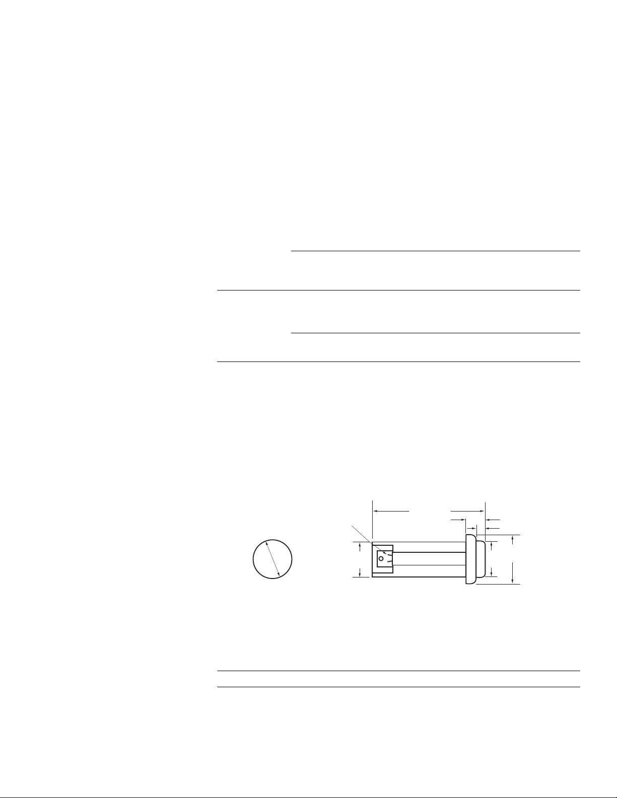
TS-8131 Unitary
Sensor
TS-9201
Duct/Immersion
Sensor
1. Determine the sensor mounting location (Figure-1).
2. Drill 17/32" (13.5 mm) diameter mounting hole.
3. Insert gasket to base of sensor “button”.
4. Insert sensor with gasket into mounting hole.
5. Secure sensor to mounting flange or surf ace by inserting Tinnerm an nut over back of
sensor.
6. Two crimp wire receptacles are provided for spade terminal connecti on to field wiring.
Requires
17/32 (13.5) Dia.
Mounting Hole
3/64 x 3/16
(1.2 x 4.8)
Tabs (2)
1/2
(12)
Figure-1 TS-8131 Mounting Dimensions.
1-3/16 (30)
5/32 (4.0)
1/4 (6)
13/16
1/2
(21)
(12)
Dimensions shown
are in inches (mm).
Duct
Note:
Hand tighten only - do not overtighten.
1. Determine the sensor mounting location on the duct (predetermine the knockout hole
location for routing of conduit). The sensing element is located within 1 inch of the end of
the sensing probe, and it should be in the air stream at a location that is typical of the
tempe ratur e requi ring s ensing. Approximat ely 3" of leng th adj ustment is available.
F-22668-5 Copyright 2008 TAC All Rights Reserved 3
Page 4
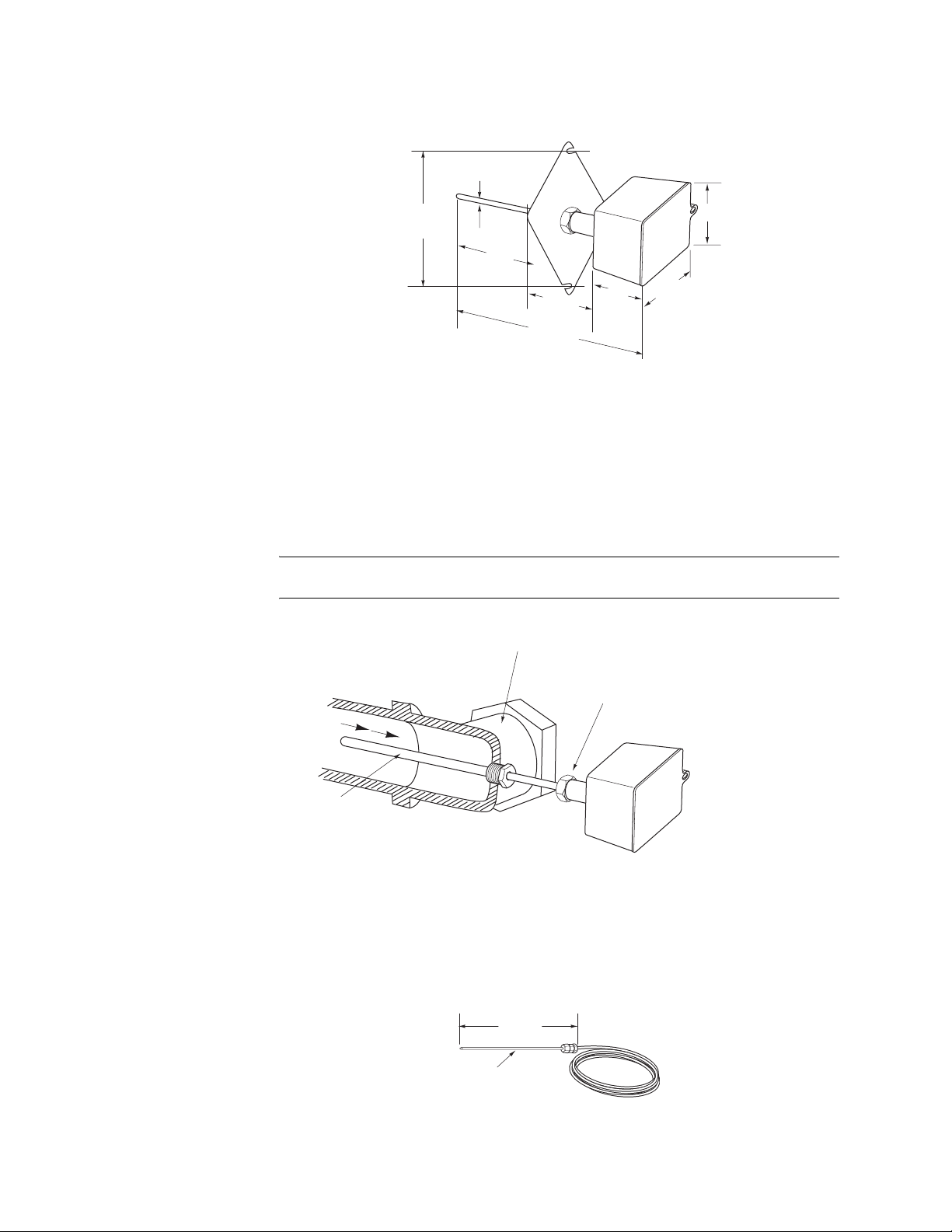
2. Use the mounting flange supplied as a templa te (or refer to Fi gure-2 for duct mounting
dimensions) f or mounting hole location.
3. Mount the sensor to the duct using the two #10 x 3/4” sheet metal screws provided.
1/4 (6) O.D.
3-25/64
(86)
8
(203)
2-1/2
(64)
13 (330)
1-5/8
(41)
Dimensions shown
are in inches (mm).
2-5/16 (59)
2-1/2
(64)
Figure-2 TS-9201 Mounting Dimensions.
Immersion (Requires AT-215 Bulb Well)
1. Remove lock nut and duct mounting flange from sensor (Figure-3).
2. Thread the sensor into AT-215 bulb well that has been installed in a liquid lin e or tank.
Note:
The AT-215 bulb well should be f il led with a temperature conductive grease (TAC
part number M-500) pr ior to element insertion, for optimum medium temperature sensing.
Tee or Elbow for Mounting Well
TS-8201-105 Duct/
Immersion Sensor
Sensor Mounting Nut
Flow
Well
AT-225
Enclosure
Figure-3 TS-9201 Immersion Mounting.
Duct (Requires AT-208 Duct Kit)
1. Determine the sensor mounting location on the duct. The sensing element is located
within 1 inch of the end of the sensing probe and it should be located in the air stream
typical of the te m peratu re requiring sensing (see Figu re-4) .
8"
(203 mm)
1/4" (6 mm) dia.
Figure-4 TS-8201-105 Mounting Dimensions.
2. Drill insertion and mounting holes for AT- 208 in the duct wall (see Figure-5).
4 Copyright 2008 TAC All Rights Reserved F-22668-5
Page 5
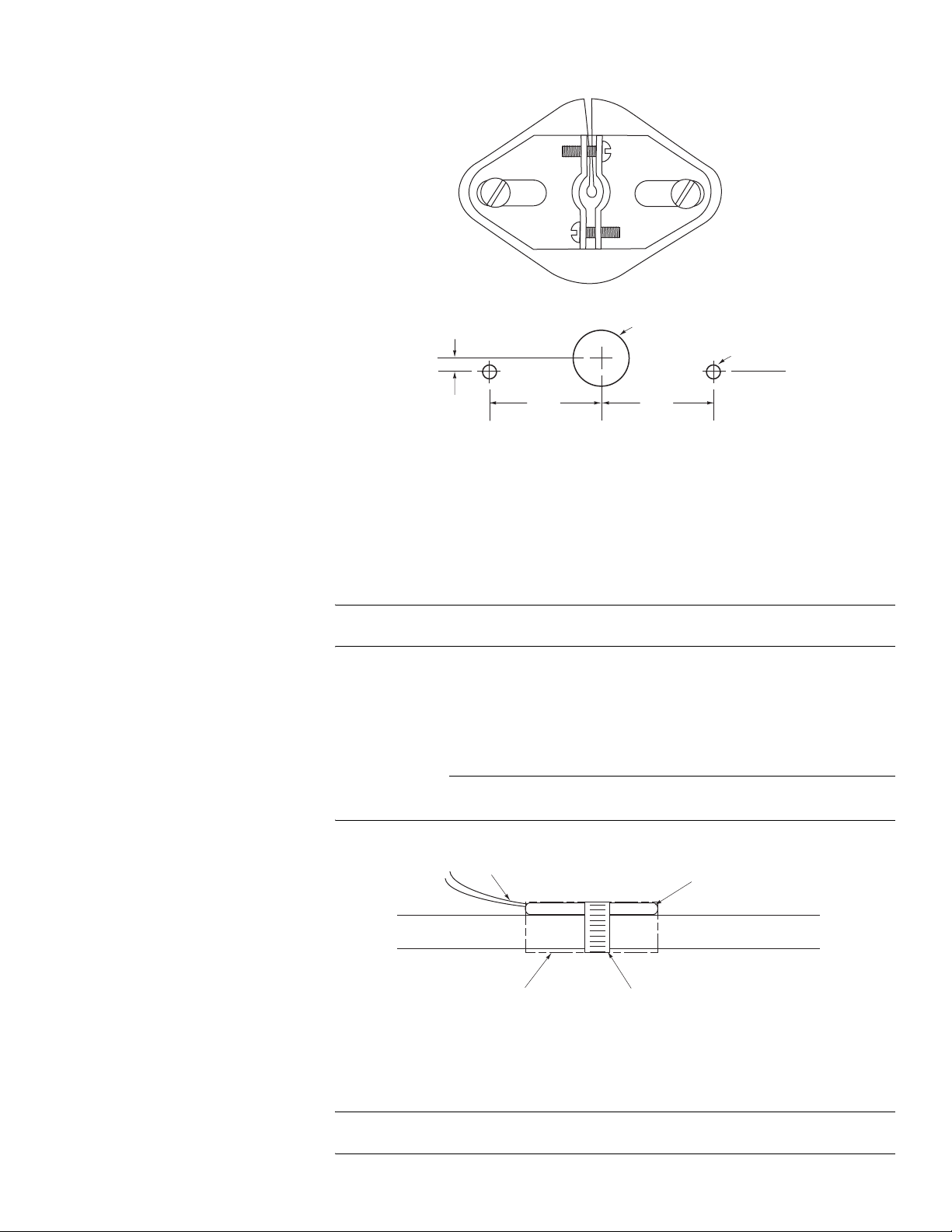
3. Mount the sensor the duct using the AT-208 kit.
AT-208 Bracket, Gasket and Mounting Screws
1/2 (13) Dia.
1/8 (3.2) Dia.
TS-8201-110 Strap-on
Sensor
1/8 (3.2)
1 (25)
Full Scale - May be used as a template.
1 (25)
Dimensions shown
are in inches (mm).
Figure-5 AT-208 Mounting Dimensions.
Immersion (Requires AT-215 Bulb Well)
Thread the sensor into AT-215 bulb well that has been ins tal led in a liquid line or tank.
Note:
The AT-215 bulb well should be f il led with a temperature conductive grease (TAC
part number M-500) pr ior to element insertion, for optimum medium temperature sensing.
1. Foam insulation tape should be placed over the sensor (Figure-6). Extend insulation
beyo nd the ends of the sensor.
2. Secure sensor and foam insulation t ape to pipe with wire ti e (factor y supp lied) or metal
hose clamp (not included).
C A U T I O N
Do not tighten clamp or nylon tie (or metal hose cla mp) to the point of distort ing the senso r.
Overtightening fasteners will cause a shift in sensed temperature.
Sensor Leads
Foam Insulation Tape
Wire Tie (factory supplied) or
Metal Hose Clamp (field supplied)
TS-8201-110
Pipe
Figure-6 TS-8201-110 Strap-On Sensor Ins tal lation.
TS-9201-106
Immersion Sensor
Thread the sensor into AT-225 bulb well that has been inst alled in a liquid l ine or tank (see
Figure-7).
Note:
The AT-225 bulb well should be f il led with a temperature conductive grease (TAC
part number M-500) pr ior to element insertion, for optimum medium temperature sensing.
F-22668-5 Copyright 2008 TAC All Rights Reserved 5
Page 6
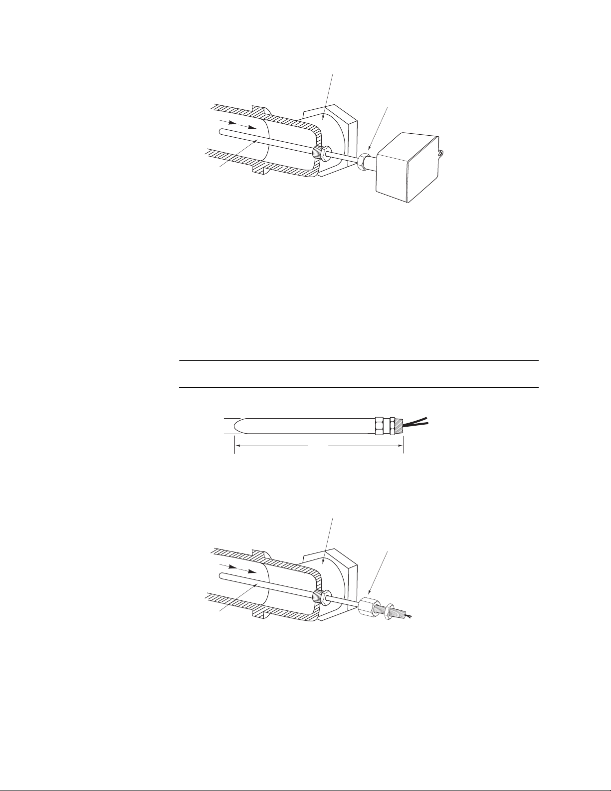
Flow
Well
AT-225
Tee or Elbow for Mounting Well
Sensor Mounting Nut
Enclosure
Figure-7 TS-9201-106 Immersion Mounting.
TS-8204
Duct/Immersion
Sensor
Duct (Requires AT-208 Duct Kit)
1. Determine the sensor mounting location on the duct. The sensing element is located
within 1" of the end of the sensing probe and it should be located in the air stream typical
of the temperature requiring sensing (see Figure-8).
2. Drill insertion and mounting holes for AT- 208 in the duct wall (see Figure-5).
3. Mount the sensor to the duct using the AT-208 kit.
Immersion (Requires AT-215 Bulb Well)
Thread the sensor into AT-215 bulb well that has been ins tal led in a liquid line tank.
Note:
The AT-215 bulb well should be f il led with a temperature conductive grease (TAC
part number M-500) pr ior to element insertion, for optimum medium temperature sensing.
1/4
(6)
Figure-8 TS-8204 Mounting Dimensions.
Tee or Elbow for Mounting Well
8
(203)
Dimensions shown
are in inches (mm).
Sensor Mounting Nut
Flow
Well
AT-225
Figure-9 TS-8204 Immersion Mounting.
TS-8241 Duffuser Th e sensor shoul d be mounted to t he face of t he ceilin g diffuser so t hat it proj ects downward
into the room (see Figure-10).
1. Drill a 7/ 16" (11 .1 mm) diameter mounting hole in the diffuser face .
2. Insert the threaded end of the sensor into th e mou nti ng hole.
3. Secure the sensor to the diffus er face using th e mounting nut and lock wash er provided .
6 Copyright 2008 TAC All Rights Reserved F-22668-5
Page 7

If the diffuser ha s an adjustable pattern, the discharge air direction must be adjusted to a
horizontal pattern. This horizontal pattern will insure a representative sample of room air
over the el em ent (see Figure-11). The sensor will not pe rform satisfactorily if the discharge
is adjusted to a verti cal pattern.
Figure-10 TS-8241 Sensor Mounted in Perforated Face Ceiling Diffuser.
TS-8241
TS-8261 Light Fixture
or Ceiling Diffuser
Sensor
Discharge Air
Induced Room Air
Figure-11 Room Air Induced over Sensor by Dischar ged Air .
The sensor may be mounte d in the return air grill of a light fixture or to the fac e of a cei li ng
diffuser using field supplied fasteners (see Figure- 12 and Figure-13).
Combination Light-Air
Diffuser Unit
Sensing Element
Room Air Entering Light Fixture through Return Grill
Access Door
Exhaust Air from
Light Fixture
Ceiling
Figure-12 TS-8261 Sensor Mounted in Light-Air Diffuser Unit.
Figure-13 TS-8261 Sensor Mounted in Perforated Ceiling Diffuser.
F-22668-5 Copyright 2008 TAC All Rights Reserved 7
Page 8

TS-9405, TS-9422
Averaging Sensors
Note:
Hand tighten only - do not overtighten.
1. Determine the sensor enclosure mounting location on the duct (see Figure 16)
(predetermine the knockout hole location for routing of conduit). The sensor should be
serpentined through the duct in a pattern that will expose it to all areas where variations
of temperature may occur. If duct can not be entered, wrap the element around a section
of conduit and place the conduit diagonally in the duct. Consider using part number
M-648 mounting clips when the inside of the duct can be accessed.
C A U T I O N
Do not make sharp bends in the elem ent.
2. Use the mounting flan ge suppl ied a s a temp late (or r efer to Fi gure 1 4 f or duc t mountin g
dimensions) f or mounting hole location.
3. Mount the sensor enclosure to the duct using the two #10 x 3/4” sheet metal screws
provided.
4-3/4
3-25/64
(86)
2-5/16 (59)
Part Element
Number Length
TS-9405 5 ft.
TS-9422 22 ft.
1-5/8
(41)
Dimensions shown
are in inches (mm).
2-1/2
(64)
Figure-14 TS-9405/9422 Mounting Dimensions.
Figure-15 TS-9405/9422 Typical Mo unti ng.
TS-8501 Outdoor Air
Sensor
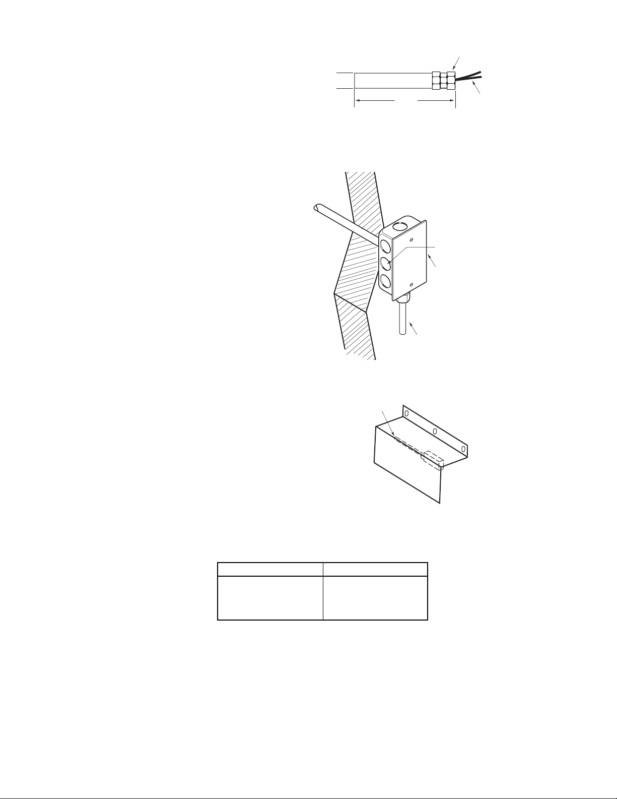
Mount sensor to water proof conduit box using the 1/2" conduit connection (see Figures 17
and 18).
Use optional shield if required by application (see Figure 19).
8 Copyright 2008 TAC All Rights Reserved F-22668-5
Page 9
(19)
(mm)
Dimensions shown
are in inches
Figure-16 TS-8501 Mounting Dimensions.
3/4
Fitting included for 1/2 in. Conduit
5
(127)
.
Outside Wall
Knockouts
Waterproof Conduit Box
(outside)
TS-8501 Sensor
2 Leads
3 ft. (0.9 m) length
Mounting Duct
Sensor Using Existing
Mounting Plate
Figure-17 TS-8501 Typical Mounting.
TS-8501 Sensor
Figure-18 TS-8501 Mounted with Shield.
Table-3 APPLICABLE MODELS.
New Part Number Old Part Number
TS-9201
TS-9201-106
TS-9405
TS-9422
TS-8201
TS-8201-106
TS-8405
TS-8422
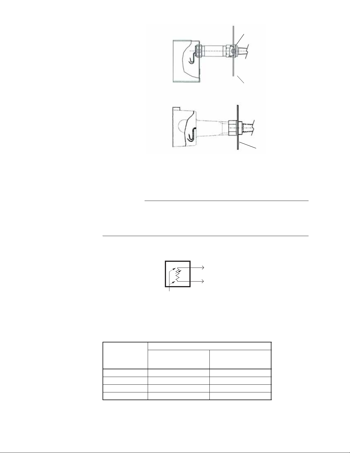
When a duct sensor is being replaced at a location wher e an existing mounting hol e size
exceeds the coverage of the adaptor flange, use the existing mounting plate as follows:
1. Remove the existing unit from the duct. Note location of the unit’s conduit hole.
2. Remove (and set aside for later use) the conduit nut securi ng the mount ing pl ate to t he
sensor.
3. Remove the mounting plate from the old sensor.
4. Place the mounting plate on the new sensor and secure wit h the conduit nut removed
from the old sensor . Do not include the plastic adaptor flange.
5. When mounting the sensor to th e duct, be sur e the condui t hole is located app ropriate ly.
F-22668-5 Copyright 2008 TAC All Rights Reserved 9
Page 10
WIRING
Conduit Nut
Mounting Plate
Adaptor Flange
Figure-19 Mounting Duct Sensor Using Existing Mounting Plate.
Two separate twisted pai r wires (six turns per foot) . Class II, low voltage, are suitable for the
sensor leads except as stated below.
C A U T I O N
Shielded cable must be used when it is necessary to install the sensor lead in the same
conduit with power wiring, or when it is known that high RFI/EMI generating devices are
near. System ground the shield at the controller only on the COM (-) terminal or blu e (-)
lead. Do not use an earth ground. Do not use the enclosure as a junct ion box for other
contro l circuits.
It is generally advisable to use flexible conduit to connect enclosure to rigid conduit.
To Energy Management
System Sensor Input
1/4" Spades
(TS-8131)
Two Leads
Figure-20 Sensor Connections.
Restrict element lead to shortest lengt h practical (see Table-4) .
Table-4 SENSOR WIRING LENGTHS.
Length of Run - ft. (m)
Wire Gauge
22 - 125 (38)
18 1000 (305) 300 (91)
16 2250 (686) 14 4000 (1219) -
TS-8xx x and TS -9xxx
Sensor to Controller
(except TP-810x)
TS-8xx x an d TS -9xxx
Sensor to TP-810x
10 Copyright 2008 TAC All Rights Reserved F-22668-5
Page 11

Table-5 TS-8000 & TS-9000 SERIES BALCO TEMPERATURE SENSORS.
T=F R=Ohms T=F R=Ohms T=F R=Ohms T=F R=Ohms T=F R=Ohms T=F R=Ohms
-50 760.8 0 854.8 50 956.9 100 1067.0 150 1185.2 200 1311.4
-49 762.6 1 856.8 51 959.0 101 1069.3 151 1187.7 201 1314
-48 764.4 2 858.8 52 961.2 102 1071.6 152 1190.1 202 1316.7
-47 766.2 3 860.7 53 963.3 103 1073.9 153 1192.6 203 1319.3
-46 768.0 4 862.7 54 965.4 104 1076.2 154 1195.0 204 1321.9
-45 769.9 5 864.7 55 967.6 105 1078.5 155 1197.5 205 1324.5
-44 771.7 6 866.7 56 969.7 106 1080.8 156 1199.9 206 1327.1
-43 773.5 7 868.6 57 971.8 107 1083.1 157 1202.4 207 1329.1
-42 775.3 8 870.6 58 974.0 108 1085.4 158 1204.9 208 1332.4
-41 777.1 9 872.6 59 976.1 109 1087.7 159 1207.3 209 1335.0
-40 779.0 10 874.6 60 978.3 110 1090.0 160 1209.5 210 1337.7
-39 780.8 11 876.6 61 980.5 111 1092.3 161 1212.3 211 1340.3
-38 782.6 12 878.6 62 982.6 112 1094.7 162 1214.8 212 1342.9
-37 784.5 13 880.6 63 984.8 113 1097.0 163 1217.3 213 1345.6
-36 786.3 14 882.6 64 986.9 114 1099.3 164 1219.7 214 1348.2
-35 788.2 15 884.6 65 989.1 115 1101.6 165 1222.2 215 1350.9
-34 790.0 16 886.6 66 991.3 116 1104.0 166 1224.7 216 1353.5
-33 791.9 17 888.6 67 993.5 117 1106.3 167 1227.2 217 1356.2
-32 793.7 18 890.7 68 995.6 118 1108.7 168 1229.7 218 1358.9
-31 795.6 19 892.7 69 997.8 119 1111.0 169 1232.2 219 1361.5
-30 797.5 20 894.7 70 1000.0 120 1113.3 170 1234.7 220 1364.2
-29 799.3 21 896.7 71 1002.2 121 1115.7 171 1237.2 221 1366.9
-28 801.2 22 898.8 72 1004.4 122 1118.0 172 1239.3 222 1369.5
-27 803.1 23 900.8 73 1006.6 123 1120.4 173 1242.3 223 1372.2
-26 804.9 24 902.8 74 1008.8 124 1122.5 174 1244.8 224 1374.9
-25 806.8 25 904.9 75 1011.0 125 1125.1 175 1247.3 225 1377.6
-24 808.7 26 906.9 76 1013.2 126 1127.5 176 1249.8 226 1380.3
-23 810.6 27 909.0 77 1015.4 127 1129.9 177 1252.4 227 1382.9
-22 812.5 28 911.0 78 1017.6 128 1132.2 178 1254.9 228 1385.6
-21 814.4 29 913.1 79 1019.8 129 1134.6 179 1257.4 229 1388.3
-20 816.3 30 915.1 80 1022.0 130 1137.0 180 1260.0 230 1391.0
-19 818.2 31 917.2 81 1024.2 131 1139.4 181 1262.5 231 1393.7
-18 820.1 32 919.2 82 1026.5 132 1141.7 182 1265.1 232 1396.4
-17 822.0 33 921.3 83 1028.7 133 1144.1 183 1267.6 233 1399.2
-16 823.9 34 923.4 84 1030.9 134 1146.5 184 1270.2 234 1401.9
-15 825.8 35 925.4 85 1033.2 135 1148.9 185 1272.7 235 1404.6
-14 827.7 36 927.5 86 1035.4 136 1151.3 186 1275.3 236 1407.3
-13 829.6 37 929.6 87 1037.6 137 1153.7 187 1277.8 237 1410.0
-12 831.5 38 931.7 88 1039.9 138 1156.1 188 1280.4 238 1412.8
-11 833.5 39 933.8 89 1042.1 139 1158.5 189 1283.0 239 1415.5
-10 835.4 40 935.9 90 1044.4 140 1160.9 190 1285.6 240 1418.2
-9 837.3 41 937.9 91 1046.6 141 1163.4 191 1288.1 241 1421.0
-8 839.3 42 940.0 92 1048.9 142 1165.8 192 1290.7 242 1423.7
-7 841.2 43 942.1 93 1051.1 143 1168.2 193 1293.3 243 1426.4
-6 843.1 44 944.2 94 1053.4 144 1170.6 194 1295.9 244 1429.2
-5 845.1 45 946.3 95 1055.7 145 1173.0 195 1298.5 245 1431.9
-4 847.0 46 948.5 96 1057.9 146 1175.5 196 1301.0 246 1434.7
-3 849.0 47 950.6 97 1060.2 147 1177.9 197 1303.6 247 1437.4
-2 850.9 48 952.7 98 1062.5 148 1180.3 198 1306.2 248 1440.2
-1 852.9 49 954.8 99 1064.8 149 1182.8 199 1308.8 249 1443.0
0 854.8 50 956.9 100 1067.0 150 1185.2 200 1311.4 250 1445.7
Table Data:
1. Material : Balc o wire calibrated fo r 1000 ohms ± 1% at 70 °F.
2. Temperature coefficient: 4300 (± 150) ppm °C between 25 and 100°C.
F-22668-5 Copyright 2008 TAC All Rights Reserved 11
Page 12

MAINTENANCE
FIELD REPAIR
3. Relationships:
R (resistance)= 0.00161T
2
+ 1.961T + 854.841
Temperature = (SQRT ((.00644 x R) - 1.6597) - 1.961) / .00322
4. Storage Temperature Specification:
Minimum = -40 °F
Maximum = 160 °F
5. Operation Temperature Specification:
Minimum = -40 °F
Maximum = 240 °F
Table Notes:
1. Temperature (T) in °F
2. Resistance (R) in ohms
3. Temperature coefficient is positive
Regular maintenance of the total system is needed to assure sustai ned optimum
performance. Sensors should be period ically inspected for dirt or blockage of air over the
elements.
These sensors are not field repairable.
Copyright 2008, TAC
All brand names, trademarks and registered
trademarks are the property of their respective
owners. Information contained within this
document is subject to change without notice.
F-22668-5
TAC
1354 Clifford Avenue
P.O. Box 2940
Loves Park, IL 61132-2940
www.tac.com
 Loading...