

Page 1
Application
TC-1191 Series
Two-Po siti o n, Ne ut ral Center
Electric Room Thermostats
General Instructions
The TC-1191 series electric room thermostats, with
neutral center, are used for low or line voltage On-Off
control of heat/cool systems such as three- or four-pipe
unitary configuration.
Features
• Anticipator available for improved performance can
be used for heating or cooling.
• Auto control of heating and cooling without external
switching means.
• UL and CSA models available for line voltage
control.
• Night depression capability.
Applicable Literature
• TAC Environmental Controls Cross-Reference
Guide
F-23638
†
†
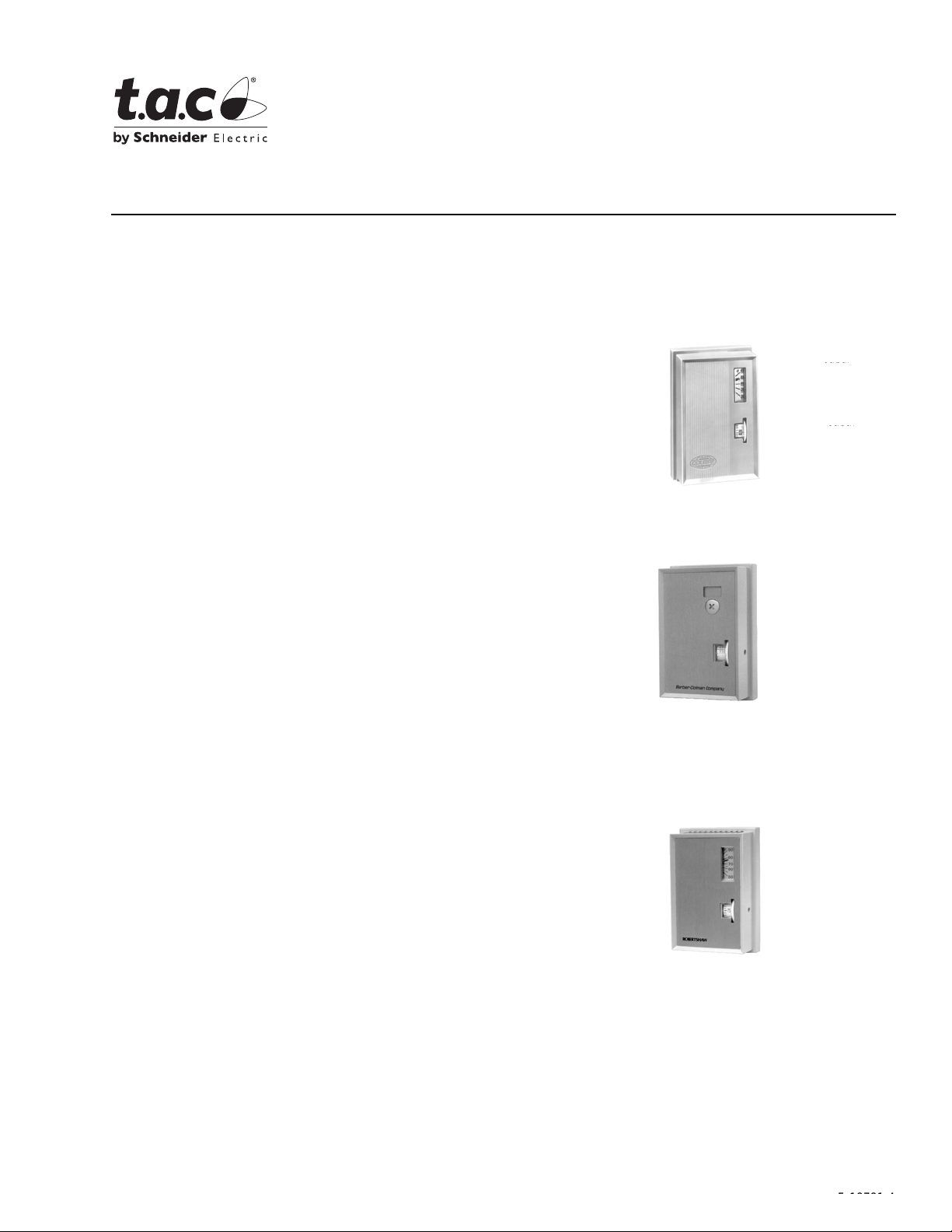
TC-1191
TC-1191 with Digital
Thermometer Kit Installed
• TAC Environmental Controls Reference Manual
F-21683
• TAC Environmental Controls Application Manual
F-21335
• Environmental Control Systems Catalog F-16650
TC-1191-770
†See Table-3 for agency approvals.
Printed in U.S.A. 8-08 © Copyright 2008 TAC All Rights Reserved. F-18781-4
F-18781-2
Page 2
SPECIFICATIONS
Part Number
TC-1191
TC-1191-116 13 to 29°C
TC-1191-500 55 to 85°F
TC-1191-602 55 to 85°F
TC-1191-770 Robertshaw 55 to 85°F
Sens ing Ele m ent: Bimetal operated snap action SPDT switch with neutral center.
Differential: 2°F (1°C) on heat, 2°F (1°C) on neutral, 2°F (1°C) on cool.
Connections: Color coded 6" leads.
Cover: Plastic as standard.
Mounting: Flush or surfa ce switch box or directly on wall (24 Vac only).
Dimensions: 4-3/8" high x 2-7/8" wide x 1-5/8" deep ( 111 mm x 73 mm x 43 mm).
Table-1 Specifications.
Company
Identification
BarberColman
*Dial stop pins included to limit dial range.
Control*
Dial Range
55 to 85°F
Full Load Amps Locked Roto r Amps
24/12 0 Vac 240 Vac 24/120 Vac 240 Vac
4.4,
Orange to
Brown L ead
3.0,
Orange to
Red Lead
2.2,
Orange to
Brown L ead
1.5,
Orange to
Red Lead
26.4,
Orange to
Brown L ead
18,
Orange to
Red Lead
13.2,
Orange to
Brown L ead
9,
Orange to
Red Lead
Pilot Duty
40 @ 24 Vac
120/24 0 Vac
Table-2 Standard Units Include the Following.
Quantity Description
1 Blank cover insert
1 Cover insert wi th setpoint dial cutout
1 5/64" Allen head screw for securing cover to thermostat base
1 5/64" Allen wrench
2 Dial stop pins to limit setpoint range
(VA)
210 @
Table-3 Agency Approvals.
Configuration Part Number UL Listed CSA Certified
Metal cover option TC2-1191* No Yes
TC-1191 Yes No
Plast i c co v er
Heat an ti ci pation or nig h t
depression options
*Only available as factory assembly. Do not convert from plastic to metal cover in the field.
TC-1191-116 Yes No
TC-1191-770 Yes No
TC-1191-500 No No
TC-1191-602 No No
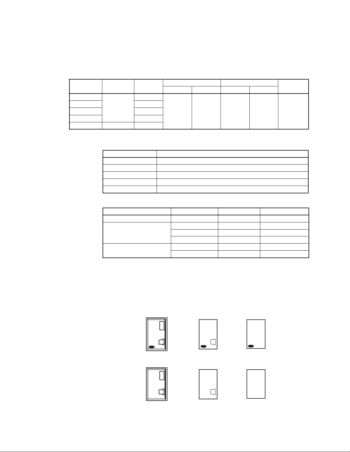
Standard C over
TC-1191
TC-1191-116
TC-1191-770
TC-1191-500 Parallel heati ng or cooling anticipati on, 24 Vac
TC-1191-602 10°F night depressi on, 24 Vac
with
TC-1191
Standard
Insert Insert
with
ROBERTSHAW
TC-1191-770
Standard
2 © Copyright 2008 TAC All Rights Reserved. F-18781-4
ROBERTSHAW
Insert Insert
ROBERTSHAW
Page 3
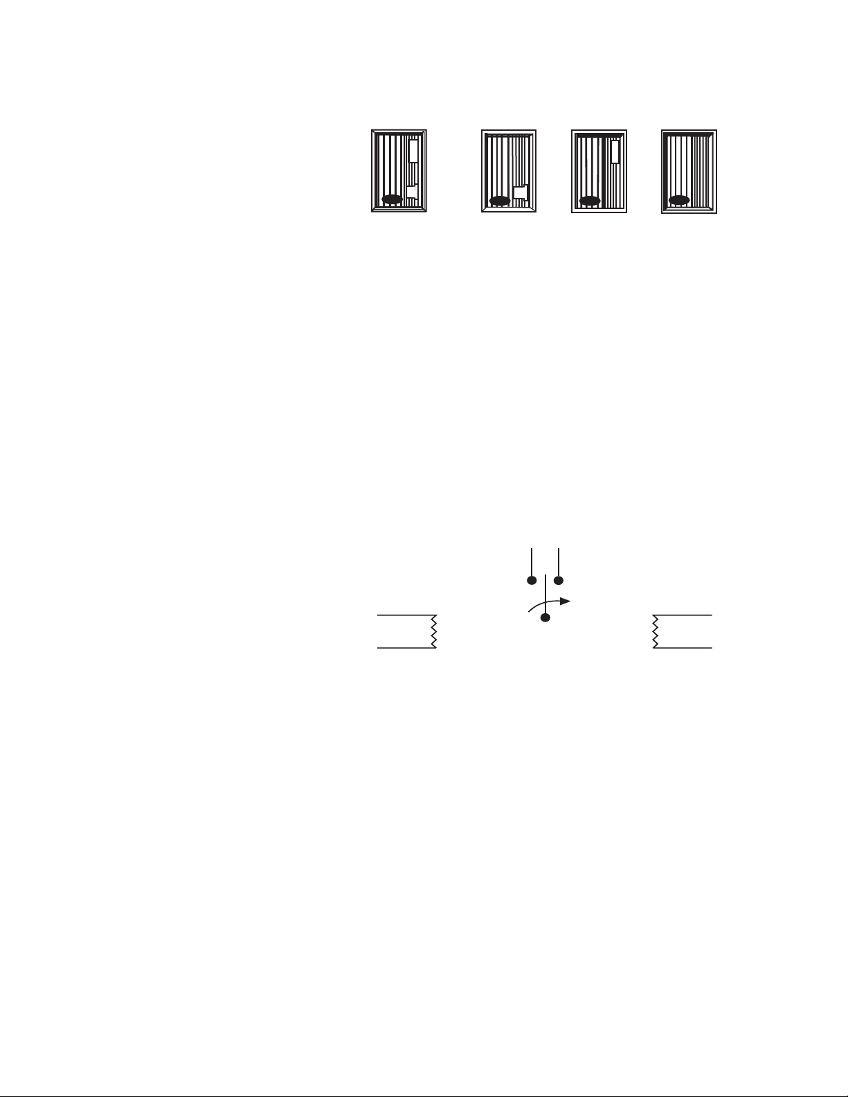
Options (for quantities of 24 or more each part number)
Add “dash-number” (-XXX) suffix to base part number for desired option.
For metal covers, specify TC2-1191.
°F°CTC-1191-399
TC-1191-398
-400
-410
†5/64" Allen screw used to secure cover.
-403†
-413†
ACCESSORIES
AT-61 Series Brushed bronz e cover plates (TAC Barber-Colman only)
AT-70 Series Brushed bronze cover plates (Robertsh aw only)
AT-82 °F digital thermometer cover kit (TAC Barber-Colman only)
AT-82-116 °C digital thermometer cover kit (TAC Barber-Colman only)
AT-82-770 °F digital thermometer cover kit (Robertshaw only)
AT-101 Lock cover kit
AT-504 Plaster hole cover kit (small)
AT-505 Surface mounting base
AT-546 Auxil iary mounting plate
AT-602 Selector switch sub-base DP4T
AT-603 Selector switch sub-base one DP4T, one DPDT
AT-1100 Series Thermost at guards
PKG-1093 Digital therm om e ter ba tte ry replac em ent kit
TOOL-11 Calibration wrench
TOOL-13 Contact burnishing tool
L1
Orange
Brown
Black/Red
Black/Red
Night Depressor
(Optional)
Black/Yellow
Black/Yellow
Heat Anticipator or
Cooling Anticipator
(Optional)
(See wiring diagram.)
Red
Temp.
Drop
Brown makes ON
temperature drop.
-404†
-414†
Figure-1 Switch Action and Terminal Identification.
F-18781-4 © Copyright 2008 TAC All Rights Reserved. 3
Page 4
TYPICAL APPLICATIONS
W
Red (Cooling)
Red
Parallel Heat Anticipation
Cooling Anticipation
Drop
Temp.
Brn.
Org.
Blk./Yel.
Blk./Yel.
Night Depression (certain models)
Load
L2
Source
Voltage
L1
Blk./Red –To Night
Blk./Red –Switch and
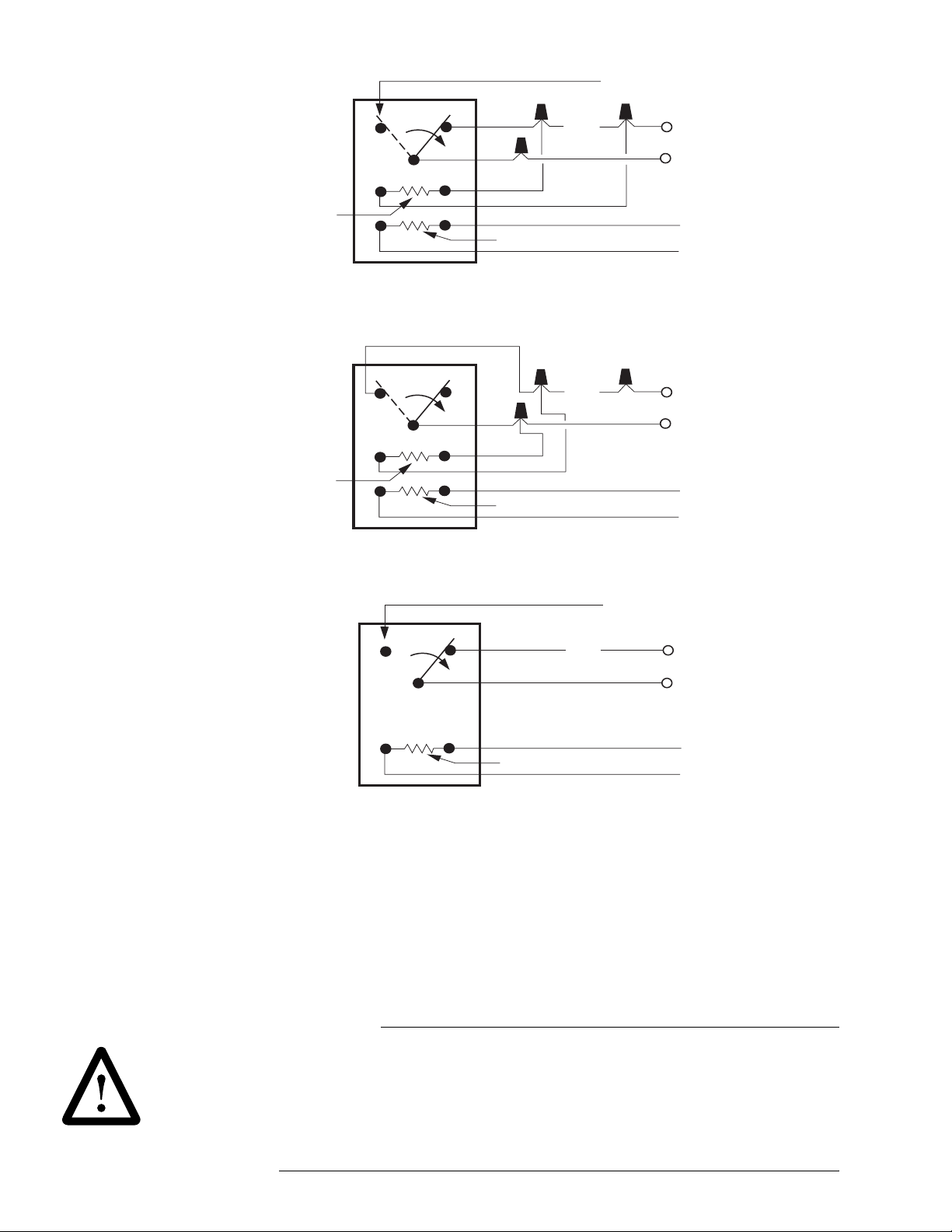
Figure-2 Typical of Parallel Heat Anticipation with or without Night Depression.
(Heater size determined by voltage.)
Drop
Temp.
Brn.
Org.
Blk./Yel.
Blk./Yel.
Night Depression (certain models)
Load
L2
Source
Voltage
L1
Blk./Red –To Night
Blk./Red –Switch and
Figure-3 Typical of Cooling Anticipation with or without Night Depression.
(Heater size determined by voltage.)
Depression
Power Supply
Depression
Power Supply
INSTALLATION
Inspection
Requirements
Red (Cooling)
Drop
Temp.
Brn.
Heat
Org.
Common
Night Depression
Load
L2
Source
Voltage
L1
Blk./Red –To Night
Depression
Blk./Red –Switch and
Power Supply
Figure-4 Typical Night Depression.
Inspect the car ton for damage. If damaged, not if y the appropriate carr ier immediately.
Inspect the device for obvious damage. Return damaged products.
• Job wiring diagrams
• Appropriate accessories
• Trai ning: Installer must be a qualified, experi enced technician
W A R N I N G
• Disconnect the power supply (line power) before installation to prevent equipment damage.
• Make all connections in accordanc e with the wiring diagram and in accordance with
national and loca l electr ical codes. Class I wiring is required unl ess all ci rcuits to cont acts
are powered from a Class II sour ce.
Use copper conductors onl y.
• Do not loc ate the thermostat near sources of heat or cold such as lamps, motors,
sunlight, or concealed ducts or pipes, or where there is a danger of electr ocution
(i.e., shower rooms).
4
Page 5
W
Mounting
W
C A U T I O N
• Do not exceed ratings of the device(s).
• The thermostat is not designed for service in any location where condensation may
occur. Avoid locations where excessive moisture, corro sive fumes, or vibration is
present. NEMA Type 1 covers are intended f or i ndoor use primarily to provide a degree
of protection against contact with the enclosed equipment.
• Thermostats with guards tha t restrict air flow must have heating or cooling anticipation.
The thermostat re quires upright mounting on a flat vertical surf ace. Locate the thermost at
where it is exposed to unrestrict ed circulation of air which represents th e average temperature of the controlled space.
1. Pull all wires from source to thermostat location.
2. Make electrical connection to t herm ostat (see Figure-2 through Figure-4).
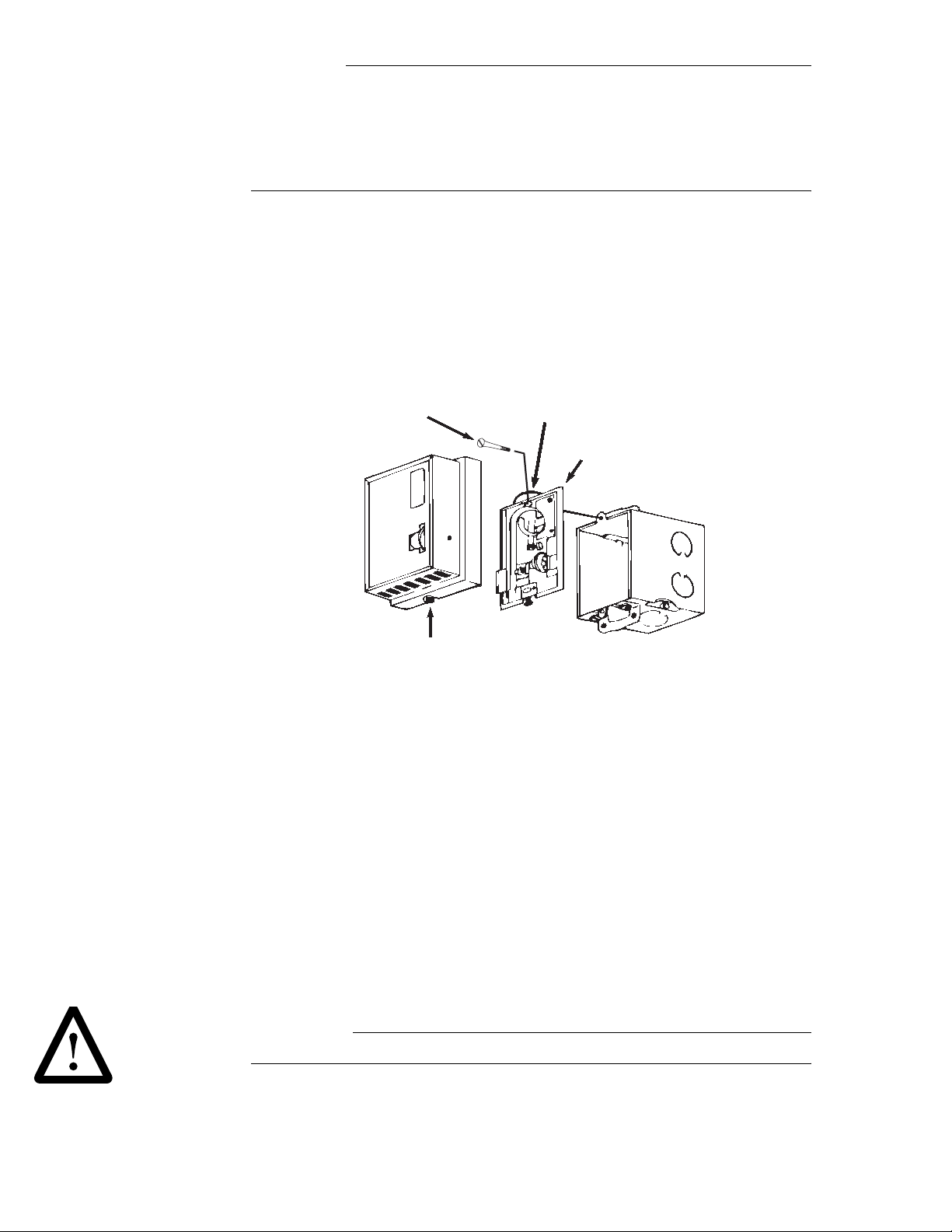
3. Remove thermostat cover and fasten thermostat to box or wall (see Figure-5).
4. Attach thermostat cover (see Figure-5).
CHECKOUT
Thermostat Mounting
Screws (2)
Thermostat
Cover Screw
Figure-5 Thermostat Mounting.
After installing a thermost at, make an initia l check of the switching action. Verify the switch
action by l istening to and watching the switch contacts or by usi ng a voltmeter between the
proper sides of the swi tch.
1. Run the set po in t dial to a t e mpe rat u re ab ov e am bie n t. This sh ou ld ca us e the t he rmo st at
to make a circuit between the orange and brown leads.
2. Slowly turn the setpoint dial sett ing to a lower temperature. This breaks the circuit
between the orange and br own leads. The contact blade i s in a neutral position between
the two contacts (not making a circuit to eith er contact). Turn the setpoi nt further down
to again lower the temperature. This causes the thermostat to make a circuit between
the orange and red lead s.
Rounded Tab Up
Mounting Plate
Switch Box
CALIBRATION
All ther mo stats are cali brated at the factory and normally do not require any such attention.
However, if recali bration is necessar y for any reason, proceed as follows:
W A R N I N G
Turn Off control power and power to night depression circuit, where applicable.
1. Set temperature dial 2°F (1°C) below actual stable room temperature, as read from an
accurate thermometer.
2. Remove cover (see Figure-5).
5
Page 6
W
C A U T I O N
W
Do not breathe on the thermostat or handle excessively as thi s affects the accuracy of
the final calib ration.
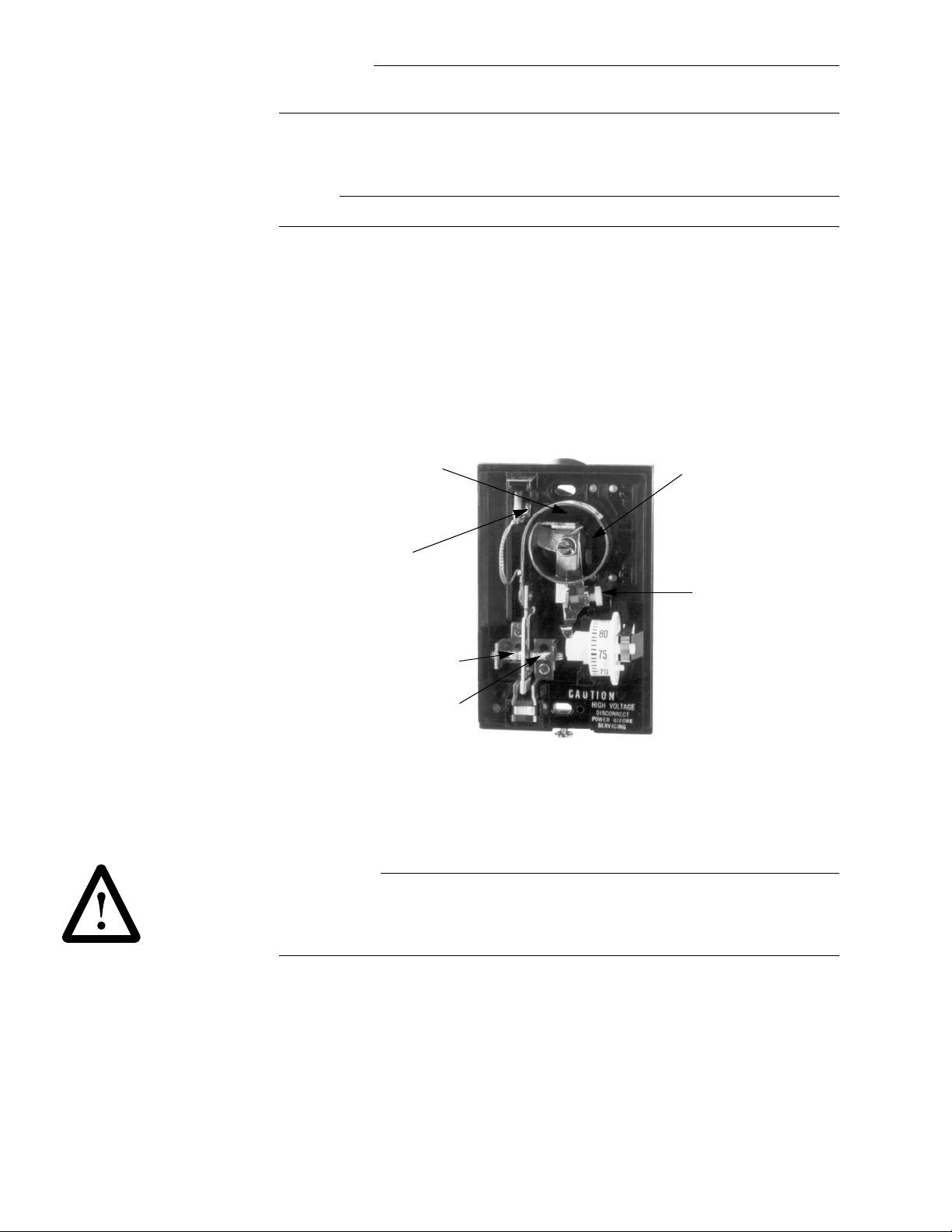
3. If the contact blade is made to the left (red lead) contact, use a 1/8" blade screwdriver
to turn the cali brati on scre w counter cl ockwise (looki ng at head o f scre w) unti l the blade
floats between the contacts.
N O T E
Each complete turn of the sc rew changes calibration approximately 15° F (8°C).
4. Now turn the screw very slowly clockwise unti l the blade just makes the left (re d lead)
contact. The the rmostat is now properly cali brated.
5. If the contact blade is originall y m ade to t he ri ght (brown lead) contact or is floating
between contacts, turn the calibration screw slowly clockwise until the element just
makes the left (red lead) contact. The therm ostat is now properly cali brated.
6. Replace the thermostat cover (see Figure-5).
7. Turn on the control power.
8. Recheck calibration about 30 minute s later to be sure heat from handli ng did not r esult
in erroneous set ti ng.
MAINTENANCE
Location for
Anticipation
Resistor, if used
Common
Red
Thermostat Contacts
to Red and Brown
Wires
Be sure that the air convection holes in the thermostat cover do not become clogged or
covered. This causes improper temperat ure sensing.
Brown
Figure-6 Part Identification.
Location for
Night Depression
Resistor, if used
Calibration
Screw
W A R N I N G
After long periods of continual use, it may become necessary to clean the contacts of any
excess co ntact buildup. Before proceeding, be sur e that either the electri cal connections to
the thermostat are disenga ged or that the power to the circ uit is broke n. Now clean the con tacts using TOOL-13 contact burnishing tool.
FIELD REPAIR
These thermostats are not field repair able. Replace entire device.
6 © Copyright 2008 TAC All Rights Reserved. F-18781-4
Page 7

F-18781-4 © Copyright 2008 TAC All Rights Reserved. 7
Page 8

Copyright 2008, TAC
All brand names, trademarks and registered
trademarks are the property of their respective
owners. Information contained within this
document is subject to change without notice.
F-18781-4
TAC
1354 Clifford Avenue
P.O. Box 2940
Loves Park, IL 61132-2940
www.tac.com
 Loading...