


Instruction Manual
MACO® 4000, 5000 & 6000 Series
SPI Auxiliary Equipment Interface
Protocol
Table of Contents
1.0 Introduction.......................................................2
2.0 Setup Instructions ............................................2
2.1 Board Location.........................................2
2.2 Jumpers and Switches.............................2
2.3 Node Address ..........................................2
2.4 MACO Serial Communication Setup........2
2.4.1 Modfiles and Sample Screens .................2
2.4.2 COMM Setpoints......................................2
2.5 Wiring.......................................................3
2.6 Error Codes Screen .................................4
2.6.1 Baud Rate Setpoints ................................4
2.6.2 SPI Status Relays ....................................4
3.0 SPI Screens and RLD Programming...............5
3.1.0 List of SPI Devices Supported .................5
3.1.1 Mold Temp Controller Commands ........... 5
3.1.2 Chiller Commands ................................... 5
3.1.3 Dryer Commands.....................................5
3.1.4 Loader Commands .................................. 6
3.1.5 Melt Pump Commands ............................ 6
3.1.6 Additive Feeder Commands .................... 6
3.1.7 Self-tune Temp Controller Commands .... 6
3.1.8 General Purpose Temp Controller
Commands...............................................6
3.1.9 Robot Commands .................................... 6
3.2 Setup Screen ...........................................7
4.0 Status and STM/MTS Control Relays..............8
4.1 Status control relays ................................ 8
4.2 STM/MTS control relays .......................... 9
4.2.1 Building the STM/MTS Table.....................9
5.0 SPI Status Monitor / setup screens...............10
1640-IN-026-A-00
July 1995
Copyright © 1995 Barber-Colman Company
1640-IN-026-A-00 Page 1 of 10

1.0 INTRODUCTION
The Society of the Plastic Industry, Inc. has established a
standard communication protocol (SPI) that provides a platform for instrumentation manufactured by different companies to communicate together on the same RS-485 local area
network.
The SPI Auxiliary Equipment Interface module (71-946-X) will
®
allow the MACO
4000, 5000 and 6000 Series controllers to
communicate (via SPI protocol) with auxiliary equipment
typically found in plastic molding, extruding or blowmolding
facilities, including mold temperature controllers, hot runner
controllers, chillers, dryers, additive feeders and melt pumps.
A maximum of 32 separate devices can be connected to a
MACO on the same SPI auxiliary interface module. With this
interface the standard features of the MACO controllers would
be utilized, such as recipe storage (allowing fast setup times)
RLD interface capability without the need for extensive wiring
to the Sequence inputs/outputs Statistical Process Control
(SPC) of auxiliary equipment parameters.
The SPI Auxiliary Equipment Interface module is pre-configured to communicate with SPI compatible auxiliary equipment. The end user or OEM needs no programming skill, or
knowledge of the intricacies of the SPI protocol. You simply
need to know what SPI compatible devices being used and
the quantity you wish to communicate with. The user needs
a working knowledge of Barber-Colman OptiGrafix and RLD
programming software.
The SPI Auxiliary module will communicate with any device
listed in the current, released version 3.01a of the SPI Phase
I protocol (also listed in section 3.1 of this document). It will
communicate at a user selectable baud rate of 1200, 2400,
4800, 9600, and 19.2K. Every "required" command, as defined by the protocol, for the devices listed are supported in
this release of firmware.
2.0 SETUP INSTRUCTIONS
U10
A-13404-2
RS-485 COMMUNICATIONS
T1
8
7
6
5
4
3
2
1
ON OFF
S1
J2
IN OUT
J1
IN OUT
4
SHIELD
3
ISOCOM
2
DATA
1
DATA
Figure 2.2 SPI Auxiliary Interface module.
2.3 Node Address
The node address switch S1 on the SPI Auxiliary module is not
used.
2.4 MACO SERIAL COMMUNICATION SETUP
The MACO serial communications setup screen (figure 2.4) is
used for setting baud rates and enabling communications.
This controller can have as many as three separate external
devices connected for use with serial communications.
Daughterboards purchased for the communications
motherboard determine what type of device can be connected. The COMM setpoints correspond to daughterboard
locations on the motherboard:
COMM 1 bottom slot.
COMM 2 middle slot.
COMM 3 upper slot.
2.4.1 Modfiles and Sample Screens
The diskette SA-00064-01X-0-00 is provided. It contains the
modfiles and sample SPI screens that will be required by the
MACO and OptiGrafix programming software. Preform the
following steps to install these files onto your user application.
2.1 Board Location
The SPI Auxiliary module may be placed in slot 1, 2, or 3 of the
communications motherboard (A-13408-1). The communications motherboard must be installed in primary chassis 1 in a
slot which has a control data bus connector; this is the middle
connector on the back-plane of the MACO controllers. You
may only have one (1) RS-485 SPI Module per system.
The SPI Auxiliary Equipment module can be used with data
handler version V20.75 or newer.
2.2 Jumpers and Switches
There are two hardware jumpers that have to be manual set
before installing the SPI Auxiliary module (daughterboard)
onto the communications motherboard A-13408-1XX.
Jumpers J1 and J2 are to be in the "IN" position, see Figure
2.2. These jumpers connect the bus termination resistors to
the Data(+) and Data(-) terminals.
1640-IN-026-A-00 Page 2 of 10
A. Copy the two modfiles; to copy the modfiles place
the diskette into floppy drive and copy to your existing modfile directory.
Example: Copy A:\modfiles\*.* C:\modfiles.
B. Using the OptiGrafix screen editor copy the SPI
sample screens from the diskette (A:\ADB0001 name
of application to copy from) to your user application
on the hard drive using the Application ...
Utilities...Copy from ... Screens Feature.
2.4.2 COMM Setpoints
Examine the Module Information Screen to determine which
communications boards are present and then enter a setpoint
for each daughterboard, see Figure 2.4. COMM 1, 2 or 3 may
be an RS-485 device (a setpoint of 0 to enable SPI communications) and COMM 1, 2 or 3 may be an RS-232 device (a
setpoint of 0, 1 or 2). Note that only one of EACH DEVICE is
allowed (i.e., can’t have two RS-232 printers or two RS-232
PCs, etc.). Al other information on this screen (Figure 2.4) is
for RS-232 communications.
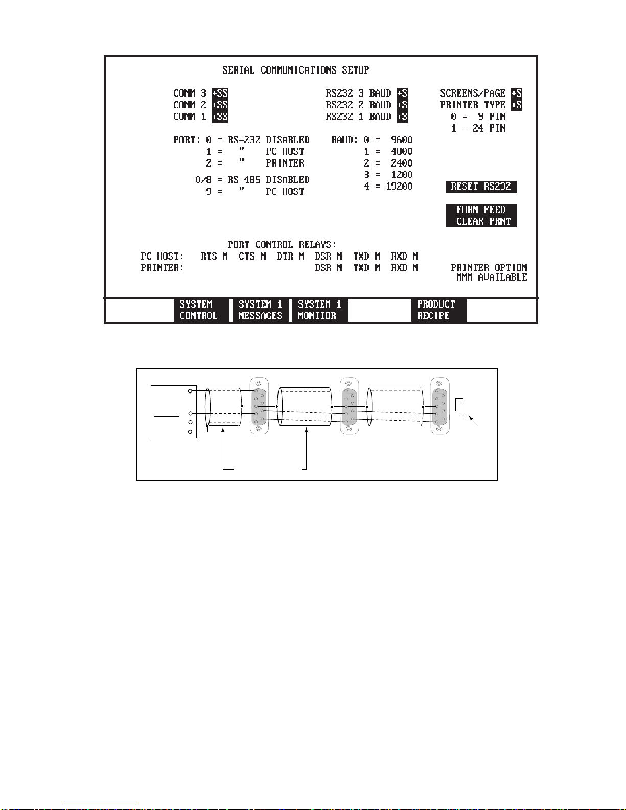
Figure 2.4 SERIAL COMMUNICATIONS SETUP SCREEN
1
ISOCOM
3
DATA (+)
1
DATA (-)
2
SHIELD
4
MACO SPI Port
1
3
3
4
8
5
9
DEVICE
NODE 1
Beldon 8772 Cable
Figure 2.5 Wire multiple Device's
2.5 Wiring
The SPI Auxiliary Interface module uses a four pin connector
to communicate with the devices. Connector E23-1134-004
is provided with screw terminals for field wiring. Figure 2.5
illustrate the device wiring, note the SPI module terminals are
not in order, see Figure 2.2.
The RS-485 cabling shall run on the low voltage side of the
MACO controllers cable tray located at the bottom of each
chassis.
The Device that is located farthest from the MACO require a
bus terminator resistor, see Figure 2.5.
1
1
3
3
4
8
5
9
DEVICE
NODE 2
9 Pin Female Connectors (Rear View)
1
3
4
5
DEVICE
NODE X
8
9
Termination
Resistor
100 Ohms
1640-IN-026-A-00 Page 3 of 10

Figure 2.6 Error Code Screen
2.6 Error Codes Screen
This screen will list sixteen (16) lines of errors. An error line will
contain the device number, CMD1 byte, CMD 2 byte, and an
error code. The command 1 and 2 bytes distinguish what
parameter failed, and the error code tells why it failed. An error
code of 16 represents that a time-out occurred, the device did
not respond to the command within the allotted one second.
Any other error code is a SPI generated error from the device
and must be interpreted based on the following definition:
BIT 7 MSbit - Invalid data
BIT 6 - Reserved by SPI
BIT 5 - Set to 1
BIT 4 - Reserved by SPI
BIT 3 - Command not supported
BIT 2 - Command not executed
BIT 1 - Invalid preamble
BIT 0 LSbit - Communication error
An error code value of 44 = 2C hex would indicate that the
device does not support this command and the command was
not executed. After 16 lines of errors have been accumulated,
or at any other time the clear error codes reverse video area
can be energized to allow for more errors to be displayed.
2.6.1 Baud Rate Setpoints
Baud rate is set by entering a baud rate setpoint on the error
code screen figure 2.6. The baud rate must match that of the
host. Enter a baud rate setpoint for each device;
0 = 9600 3 = 1200
1 = 4800 4 = 19200
2 = 2400
If the baud rate setpoint is not programmed on a screen it
defaults to 9600 baud.
2.6.2 SPI Status Relays
The SPI status relays are located on the middle right of the
Error Code screen and indicate the status of any ongoing
communications. SPI status is indicated by “TXD” or an
“RXD” will indicate direction (transmit or receive) and an
asterisk will indicate if data is actually being transmitted or
received (these are not “real time” indicators - they are meant
only to show that communication is taking place).
1640-IN-026-A-00 Page 4 of 10

3.0 SPI SCREENS AND RLD PROGRAMMING
The SPI screens will depend on the type(s) of SPI devices that
will be connected to the SPI Auxiliary Equipment Interface. An
example would be one user wants to connect a mold temperature controller as device one (1) and a different user might
want a melt pump as device one (1). The mold temperature
controller has four setpoints and two values that are read back
to the screen, whereas a melt pump has seven setpoints and
three values updated to the MACO. The standard screens
have device one setup as a mold temperature controller, to
support a melt pump three additional setpoints and two
additional values would have to be added to the screen. Also
the text used to describe the process status control relays
would differ between the two devices.
There is no RLD programming required to transfer setpoints
and values from a SPI device to the MACO. RLD programming is only necessary when you want to incorporate the
status returned from the device, such as alarm monitoring or
for example turn the auxiliary device ON/OFF.
3.1.0 List of SPI Devices Supported
1 - Mold Temperature Controller
2 - Chiller
3 - Dryer
4 - Loader
5 - Melt Pump
6 - Additive Feeder
7 - Self-Tuning Temperature Controller
8 - General Purpose Temperature Controller
11 - Robot
The Device number in the following descriptions depends on
the device address assignment the user on the SPI setup
screen. The modfile column is the descriptor from the modfile
definitions provided for screen building, see tabbed sections
of this manual. The version (ASCII string is the software
version descriptor that a device manufacture defines.
The machine mode control relay command can be used to
toggle the auxiliary equipment on/off with the use of a user
defined STM relay (see Control Relay Listing on defining
STM/MTS control relays). This command is not supported by
all the auxiliary equipment manufactures. If a response is not
received for this command five times, the command will not be
asked for again until a system reset occurs.
Sequence to Module (STM) is used to transmit the status of
control relays in the sequence modules to other non-sequence modules in a MACO system.
Module to Sequence (MTS) is used to transmit the status of
non-sequence module control relays to all sequence modules.
3.1.1 Mold Temp Controller Commands
Setpoints Modfile Values Modfile Control Relay Modfile
Process temperature (SP 1 Dev #) Temp to process (Value 1 Dev#) Process Status (Dev# CR1-CR16)
High temperature deviation (SP 2 Dev #) Version (ASCII string) Machine Mode (STM) (Dev# CR17-CR32)
Low temperature deviation (SP 3 Dev #)
Echo (ASCII string) (Echo Dev #)
3.1.2 Chiller Commands
Setpoints Modfile Values Modfile Control Relay Modfile
Process temperature (SP 1 Dev #) Temp to process (Value 1 Dev#) Process Status (Dev# CR1-CR16)
High temperature deviation (SP 2 Dev #) Version (ASCII string) Machine Mode (STM) (Dev# CR17-CR32)
Low temperature deviation (SP 3 Dev #)
Echo (ASCII string) (Echo Dev #)
3.1.3 Dryer Commands
Setpoints Modfile Values Modfile Control Relay Modfile
Process temperature (SP 1 Dev #) Temp to process (Value 1 Dev#) Process Status (Dev# CR1-CR16)
High temperature deviation (SP 2 Dev #) Version (ASCII string) Machine Mode (STM) (Dev# CR17-CR32)
Low temperature deviation (SP 3 Dev #)
Echo (ASCII string) (Echo Dev #)
1640-IN-026-A-00 Page 5 of 10

3.1.4 Loader Commands
Setpoints Modfile Values Modfile Control Relay Modfile
Load Time A (SP 1 Dev#) Version (ASCII string) Process Status (Dev# CR1-CR16)
Load Time B (SP 2 Dev#) Material Mode (STM) (Dev# CR17-CR32)
Echo (ASCII string) (Echo Dev#)
3.1.5 Melt Pump Commands
Setpoints Modfile Values Modfile Control Relay Modfile
RPM (SP 1 Dev#) Inlet Pressure (Value 1 Dev#) Process Status (Dev# CR1-CR16)
High RPM deviation (SP 2 Dev#) Outlet Pressure (Value 2 Dev#) Machine Mode (STM) (Dev# CR17-CR32)
Low RPM deviation (SP 3 Dev#) RPM (Value 3 Dev#)
Inlet Pressure (SP 4 Dev#) Version (ASCII string)
High Pressure deviation (SP 5 Dev#)
Low Pressure deviation (SP 6 Dev#)
Echo (ASCII string) (Echo Dev#)
3.1.6 Additive Feeder Commands
Setpoints Modfile Values Modfile Control Relay Modfile
Additive setpoint (SP 1 Dev#) Material Usage (Value 1 Dev#) Process Status (Dev# CR1-CR16)
Reference setpoint (SP 2 Dev#) Version (ASCII string) Machine Mode (STM) (Dev# CR17-CR32)
Calibration setpoint (SP 3 Dev#)
Echo (ASCII string) (Echo Dev#)
3.1.7 Self-tune Temp Controller Commands
Setpoints Modfile Values Modfile Control Relay Modfile
Process temperature (SP 1 Dev#) Process Value (Value 1 Dev#) Alarm Active (Dev# CR1-CR16)
Cycle Time 1 (SP 2 Dev#) Version (ASCII string)
Echo (ASCII string) (Echo Dev#)
3.1.8 General Purpose Temp Controller Commands
Setpoints Modfile Values Modfile Control Relay Modfile
Process temperature (SP 1 Dev#) Process Value (Value 1 Dev#) Alarm Active (Dev# CR1-CR16)
Cycle Time 1 (SP 2 Dev#) Version (ASCII string)
Proportional Band 1 (SP 3 Dev#)
Reset 1 (SP 4 Dev#)
Rate 1 (SP 5 Dev#)
Echo (ASCII string) (Echo Dev#)
3.1.9 Robot Commands
Setpoints Modfile Values Modfile Control Relay Modfile
Echo (ASCII string) (Echo Dev#) Version (ASCII string) Process Status (Dev# CR1-CR16)
Sequence Selection (Dev# CR17-CR32)
1640-IN-026-A-00 Page 6 of 10

Figure 3.2 Setup Screen
3.2 Setup Screen
This screen allows the user to choose what SPI Auxiliary
Equipment device(s) will be communicating to the MACO.
The first setpoint entry in the device address assignments
section should correspond to your SPI equipment which you
have configured as device address 20 hex. Device 2 would
have device address 21 hex. If device address 20H is a dryer,
you should enter a setpoint of three (3) for this setpoint. You
continue entering setpoints for all of the SPI equipment you
wish to communicate with.
If your SPI device is a Self-Tuning or General Purpose
temperature controller types seven (7) or eight (8), you must
enter in a zone number for each zone of the controller you
wish to communicate with. A controller zone occupies one
device slot, for example if a Self-Tuning temperature controller with 32 zones of control, you would enter in a seven (7) for
all 32 device address assignment setpoints, and a setpoint of
1 through 32 for each of the 32 device zone number setpoints.
If the 10th device on your SPI network is a self-tuning or
general purpose controller with three zones of control. Enter
a one (1) for the device zone number setpoint 10, for zone
setpoint 11 enter a two (2), and for zone setpoint 12 enter a
3. A seven (7) or eight (8) must be entered in the device
address assignment setpoint 11 & 12.
Note: The device zone number for type 7 & 8 setpoints could
be removed by the user with OptiGrafix if SPI device types 7
& 8 are not used.
1640-IN-026-A-00 Page 7 of 10

4.0 STATUS AND STM/MTS CONTROL RELAYS
Status control relays are used to display messages on the
operator station, STM relays (CR# 3769 - 3832) and MTS
relays (CR# 3833 - 3896) are used in RLD.
4.1 Status control relays
Any control relay retrieved from the SPI equipment can be
used to display messages on the operator station, this is
known as a status control relay. Each of the 32 devices that
can be connected to the SPI interface can have 32 status
Process Status Modfile Definition Machine Mode Modfile Definition
bit 0 - processing Dev. 1 CR1 bit 0 - machine, ON/OFF Dev. 1 CR17
bit 1 - system alarm Dev. 1 CR2 bit 1 - alarm acknowledge Dev. 1 CR18
bit 2 - process alarm Dev. 1 CR3 bit 2 - reserved Dev. 1 CR19
bit 3 - machine alarm Dev. 1 CR4 bit 3 - reserved Dev. 1 CR20
bit 4 - reserved Dev. 1 CR5 bit 4 - reserved Dev. 1 CR21
bit 5 - reserved Dev. 1 CR6 bit 5 - reserved Dev. 1 CR22
bit 6 - reserved Dev. 1 CR7 bit 6 - reserved Dev. 1 CR23
bit 7 - reserved Dev. 1 CR8 bit 7 - reserved Dev. 1 CR24
bit 8 - reserved Dev. 1 CR9 bit 8 - reserved Dev. 1 CR25
bit 9 - reserved Dev. 1 CR10 bit 9 - reserved Dev. 1 CR26
bit 10 - augur jam alarm Dev. 1 CR11 bit 10 - reserved Dev. 1 CR27
bit 11 - low material alarm Dev. 1 CR12 bit 11 - reserved Dev. 1 CR28
bit 12 - reserved Dev. 1 CR13 bit 12 - reserved Dev. 1 CR29
bit 13 - reserved Dev. 1 CR14 bit 13 - reserved Dev. 1 CR30
bit 14 - open Dev. 1 CR15 bit 14 - reserved Dev. 1 CR31
bit 15 - open Dev. 1 CR16 bit 15 - reserved Dev. 1 CR32
control relays, for a total count of 1,024. Status control relays
cannot be used in the RLD and are listed in the Control Relay
section of this manual.
The first sixteen (16) status control relays are always linked to
the first supported control relay command (see 3.1.1 - 3.1.9)
and the next sixteen are linked to the second control relay
command.
For an example look at an additive feeder assigned as device
one (1) on the setup screen. The process status and machine
mode definition is a follows:
Table 1 Process Status and Machine Node with a additive feeder as Dev. 1
For an example look at a chiller assigned as device four (4) on the setup screen. The process status and machine mode
definition is a follows:
Process Status Modfile Definition Machine Mode Modfile Definition
bit 0 - processing Dev. 4 CR1 bit 0 - machine, ON/OFF Dev. 1 CR17
bit 1 - system alarm Dev. 4 CR2 bit 1 - alarm acknowledge Dev. 4 CR18
bit 2 - process alarm Dev. 4 CR3 bit 2 - reserved Dev. 4 CR19
bit 3 - machine alarm Dev. 4 CR4 bit 3 - reserved Dev. 4 CR20
bit 4 - high temp. alarm Dev. 4 CR5 bit 4 - reserved Dev. 4 CR21
bit 5 - low temp. alarm Dev. 4 CR6 bit 5 - reserved Dev. 4 CR22
bit 6 - high pressure alarm Dev. 4 CR7 bit 6 - reserved Dev. 4 CR23
bit 7 - low pressure alarm Dev. 4 CR8 bit 7 - reserved Dev. 4 CR24
bit 8 - reserved Dev. 4 CR9 bit 8 - reserved Dev. 4 CR25
bit 9 - low flow alarm Dev. 4 CR10 bit 9 - reserved Dev. 4 CR26
bit 10 - reserved Dev. 4 CR11 bit 10 - reserved Dev. 4 CR27
bit 11 - reserved Dev. 4 CR12 bit 11 - reserved Dev. 4 CR28
bit 12 - reserved Dev. 4 CR13 bit 12 - reserved Dev. 4 CR29
bit 13 - reserved Dev. 4 CR14 bit 13 - reserved Dev. 4 CR30
bit 14 - open Dev. 4 CR15 bit 14 - reserved Dev. 4 CR31
bit 15 - open Dev. 4 CR16 bit 15 - reserved Dev. 4 CR32
Table 2 Process Status and Machine Node with a chiller as Dev. 4
If you were interested in placing the status of the system alarm
(table 1) from the process status on the operator station, you
would use Dev. 1 CR #2 from the SPI modfile. If you wanted
to know the status of the machine on/off bit (table 1), you
would use Dev. 1 CR #17.
1640-IN-026-A-00 Page 8 of 10

4.2 STM/MTS control relays
Figure 4.2 STM & MTS Control Relays Screen
There are 56 user-definable STM control relays (CR# 3777 -
3832) and 56 user definable MTS relays (CR# 3841 - 3896)
to be used in RLD. Any of the control relay commands read
back from the SPI equipment can be setup as a MTS, but only
those with a STM next to them (see 3.1.1 and 3.1.9) can be
setup as STM relays. MTS relays are typically setup in RLD
to monitor alarms or faults in the auxiliary equipment and react
accordingly in the RLD. STM relays are typically used in RLD
to turn on/off the auxiliary equipment and acknowledge alarms.
4.2.1 Building the STM/MTS Table
Table Figure 4.2, is used for defining which relays from the SPI
equipment are assigned as usable in RLD. The user can
define 56 MTS relays, with up to 32 MTS relays for a single
device. Refer to the bit definitions listed in table 1 for the
process status and machine mode commands for an additive
feeder as device one (1). If you wanted to assign the process
alarm of device number one as your first MTS relay, you would
enter a setpoint of 102. The one (1) represents the device
address number, and the 02 (bit number) is assigned to the
process alarm. If you wanted the process alarm from the
sixteenth (16) device, the setpoint entered would be 1602.
The first MTS setpoint entered links CR #3841 with the device
and bit definition encoded in the setpoint definition. Therefore, you can assign CR #3841 in your RLD to react accordingly based on your first MTS setpoint. The second setpoint
entered affects CR #3842. The user defines the CR meaning
based on the setpoints entered on this screen. For devices
with two control relay commands, the setpoints would range
from 100-131 for device address number one, and 3200-3231
for device address number thirty-two (32).
The user can also define up to 56 STM relays. Only those
control relay commands with a (STM) next to the command
can be setup. The setpoints range from 116-131 for device
address number one, and 3216-3231 for device address
number thirty-two (32). The setup of the STM relays is the
same as the MTS relays, except the setpoints entered affect
CR #3777 - CR #3832. In order to assign STM CR #3777 to
turn on/off your chiller at device address one, you would enter
a setpoint of 116 for STM setpoint number one.
CR #3841
PROCESS ALARM
(SPI DEV. 1 BIT 2 SP=102)
CR #1657
OPERATOR CR
OUT 1
CR #3777
CHILLER
ON/OFF
After you have defined all of your MTS and STM setpoints you
must activate the BUILD STM/MTS TABLE reverse video
area or energize CR #3769. Once the table is built CR #3833
will be energized. This is indicated by an asterisk next to the
build STM/MTS table. You must rebuild the table anytime you
change any MTS or STM setpoint.
MTS Control Relays STM Control Relays
3833 - STM/MTS table is built 3769 - Build STM/MTS table
3834 - Reserved 3770 - Reserved
3835 - Reserved 3771 - Reserved
3836 - Reserved 3772 - Reserved
3837 - Reserved 3773 - Reserved
3838 - Reserved 3774 - Reserved
3839 - Reserved 3775 - Reserved
3840 - Reserved 3776 - Reserved
3841 - 3896 = User define MTS 3777 - 3832 =User define STM
1640-IN-026-A-00 Page 9 of 10

5.0 SPI STATUS MONITOR / SETUP SCREENS
Seven screens are provided to monitor the status or setup of
each SPI device. Each screen displays five devices and their
variables.
Figure 5.0 SPI Status Monitor Screens
Barber-Colman Company
INDUSTRIAL INSTRUMENTS DIVISION
1354 Clifford Avenue
Loves Park, IL U.S.A. 61132-2940
1-815-637-3000
1640-IN-026-A-00 Page 10 of 10
 Loading...