


DYNA 8000
TECHNICAL MANUAL
FOR
DYNA 8000, 8200 & 8400
ELECTRONIC GOVERNOR
DYNA 8000
DYNA 8400
DYNA 8200
DYNA 8000-400 & DYNA 8400-400
F-23721-5

CONTENTS
SECTION DESCRIPTION PAGE
1 GENERAL INFORMATION........................... 3
2 SPECIFICATIONS.........................................3
3 FUNCTIONAL DESCRIPTION .....................5
4 INSTALLATION.............................................6
5 CALIBRATION OF DYN1-1065X.................. 9
6 CALIBRATION OF DYN1-1068X................ 11
7 TROUBLESHOOTING................................13
8 INSTALLATION DIMENSIONS................... 15
2

1. GENERAL INFORMATION
1.1 INTRODUCTION
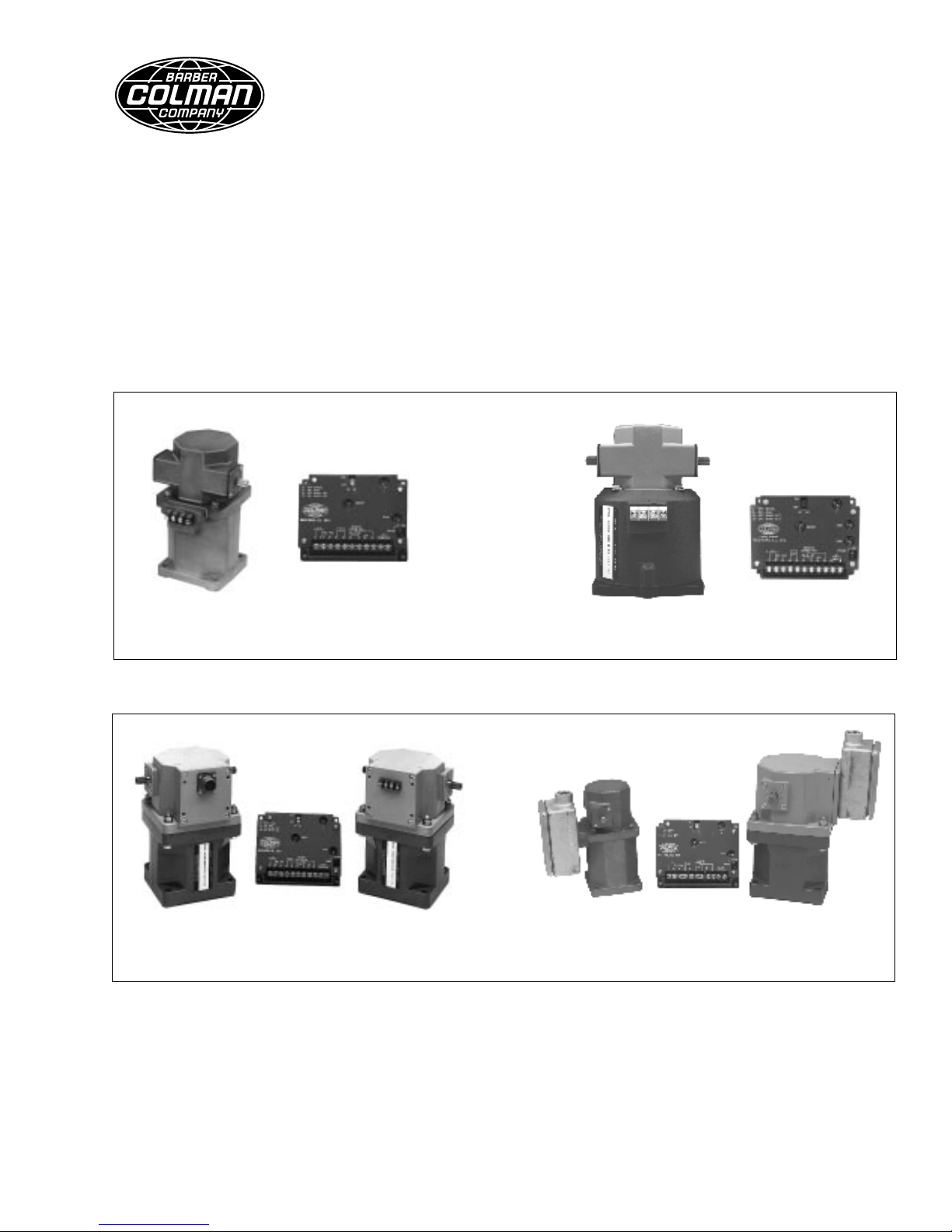
The DYNA 8000, DYNA 8200 and DYNA 8400 governor system
provides an engine governor for speed and power control of
piston and gas turbine engines or steam and water turbines.
The actuator is a simple, proportional, electric solenoid having
a sliding armature whose magnetic force is proportional to input
coil current. The armature glides on anti-friction bearings and is
balanced between the force of its return spring and the magnetic force, thus providing a hysteresis-free linear movement.
The linear motion is converted to an output shaft rotation by a
crank arm.
The hazardous duty DYNA 8000 and DYNA 8400 actuators
provide units that are UL listed for Class I, Division 2, Group D,
hazardous duty applications that are often encountered in the
petroleum or chemical industries. The hazardous duty actuators can be used to provide an engine governor for speed and
power control of piston and gas turbine engines.
1.2 TYPICAL APPLICATIONS
Typical applications are speed governing, remote throttle control, generator sets, power carts and pump set applications.
1.3 STANDARD FEATURES
• All electric
• All engine compatible
• Mounts in any position
• Engine mounted (actuator only)
• High reliability due to few moving parts
• Proportional actuator
• No hydraulic or oil lines
• No special maintenance
• Spring returns output shaft to minimum position on removal
of power or loss of magnetic pickup signal
• Precise repeatability
2.1.10 DYNA 8000 CONTROLLER
Output Current
@ 12 VDC
Output Current
@ 24 VDC
Weight
2.1.11 DYNA 8000 CONTROLLER
INPUT SIGNAL FREQUENCY
Input Signal
Frequency in Hertz
Select controller for the correct input signal frequency range
generated by the magnetic pickup at the maximum engine
operated (RPM) speed.
2.1.12 AVAILABLE CONTROLLER MODELS
Controllers: Speed Input Signal Frequency
Nominal Quiescent Current 80 mA
Maximum Amperes @ Stall 13 amps
Nominal Quiescent Current 80 mA
Maximum Amperes @ Stall 13 amps
Kilograms 0.863
Pounds 1.9
Engine RPM x Number of Gear
=
Teeth on Flywheel
60 Seconds
• DYN1-10652-000-0-12/24 250 - 1200 Hz
• DYN1-10653-000-0-12/24 1200 - 2500 Hz
• DYN1-10654-000-0-12/24 2500 - 5000 Hz
• DYN1-10656-000-0-12/24 5000 - 9500 Hz
• DYN1-10682-000-0-12/24 250 - 1200 Hz
• DYN1-10683-000-0-12/24 1200 - 2500 Hz
• DYN1-10684-000-0-12/24 2500 - 5000 Hz
• DYN1-10686-000-0-12/24 5000 - 9500 Hz
2.2. DYNA 8000 & DYNA 8000 UL APPROVAL,
HAZARDOUS DUTY, CLASS 1, DIVISION 2, GROUP D
ACTUATOR SPECIFICATIONS
2.2.1 Operating Voltage: 12 VDC or 25 VDC ±20%
2. SPECIFICATIONS
2.1 CONTROLLER SPECIFICATIONS
2.1.1 Operating Voltage: 12 VDC or 24 VDC ±20%
2.1.2 Ambient Operating Temperature:
-40 to +180°F (-40 to +85°C).
2.1.3 Temperature Stability: Better than ±0.5% over a
temperature range of -40 to +167°F (-40 to +75°C).
2.1.4 Steady State Speed Band: ±0.25%
2.1.5 Adjustments: Speed, Gain, Integral, and Droop.
2.1.6 Circuit Boards: Boards are covered with a heavy
conformal coating for moisture and vibration protection.
2.1.7 Connection: Terminal strip.
2.1.8 Mechanical Vibration: Withstands the following vibra-
tion without failure of degraded performance: 0.06 inch double
amplitude at 5 to 18 Hz; 1 G at 18 to 30 Hz; 0.02 inch double
amplitude at 30 to 48 Hz; 2.5 G's at 48 to 70 Hz.
2.1.9 The same DYN1-1065X or DYN1-1068X Series can be
used on a DYNA 8000, DYNA 8200 or DYNA 8400 actuator.
The DYN1-1068X governor control box provides a wider range
of adjustment than the DYN1-1065X. The DYN1-1068X can be
used where maximum performance is desired or for some
engines which are possibly more difficult to control.
2.2.2 Ambient Operating Temperature:
-65 to +255°F (-55 to +125°C).
2.2.3 Sealed Unit: Oil, water and dust tight.
2.2.4 Connection: Terminal strip or "MS" Connector.
2.2.5 Mechanical Vibration: 5 to 500 Hz, Curve F, per
MIL-STD. 810D, Method 514-2.
2.2.6 DYNA 8000 ACTUATORS
Work
Torque
Output
Weight
Current @
12 VDC
Current @
24 VDC
Nominal Response Time for 63% of Stroke
(Seconds)
3
Joules 1.2
Foot-Pounds 0.9
Newton-Meters 1.4
Pound-Foot 1.0
Rotary 35°
Kilograms 5
Pounds 11.0
Maximum Amperes @ Stall 12.5
Nominal Steady State Amperes 3.5
Maximum Amperes @ Stall 9.5
Nominal Steady State Amperes 1.5
0.030

2.2.7 AVAILABLE DYNA 8000 ACTUATOR MODELS
WITH CLOCKWISE OUTPUT SHAFT ROTATION
(Standard Mounted Units)
• DYNC-11020-000-0-12 Standard Clockwise
DYNC-11020-000-0-24 Output Shaft Rotation
2.2.11 AVAILABLE DYNA 8000 HAZARDOUS DUTY
ACTUATOR MODELS WITH CLOCKWISE OUTPUT SHAFT
ROTATION (Standard Mounted Units)
• DYNC-11020-400-0-12 Standard Clockwise
DYNC-11020-400-0-24 Output Shaft Rotation
• DYNC-11021-000-0-12 Actuator Head Positioned 180°
DYNC-11021-000-0-24 from Standard DYNC-11020
• DYNC-11022-000-0-12 Actuator Head Positioned 90°
DYNC-11022-000-0-24 CCW from Standard DYNC-11020
• DYNC-11023-000-0-12 Actuator Head Positioned 90°
DYNC-11023-000-0-24 CW from Standard DYNC-11020
2.2.8 AVAILABLE DYNA 8000 ACTUATOR MODELS
WITH CLOCKWISE OUTPUT SHAFT ROTATION
(Side Mounted Units)
• DYNC-11020-300-0-12 Standard Clockwise
DYNC-11020-300-0-24 Output Shaft Rotation
• DYNC-11021-300-0-12 Actuator Head Positioned 180°
DYNC-11021-300-0-24 from Standard DYNC-11020
• DYNC-11022-300-0-12 Actuator Head Positioned 90°
DYNC-11022-300-0-24 CCW from Standard DYNC-11020
• DYNC-11023-300-0-12 Actuator Head Positioned 90°
DYNC-11023-300-0-24 CW from Standard DYNC-11020
2.2.9 AVAILABLE DYNA 8000 ACTUATOR MODELS
WITH COUNTERCLOCKWISE OUTPUT SHAFT
ROTATION (Standard Mounted Units)
• DYNC-11024-000-0-12 Standard Clockwise
DYNC-11024-000-0-24 Output Shaft Rotation
• DYNC-11025-000-0-12 Actuator Head Positioned 90°
DYNC-11025-000-0-24 CW from Standard DYNC-11024
• DYNC-11026-000-0-12 Actuator Head Positioned 180°
DYNC-11026-000-0-24 CCW from Standard DYNC-11024
• DYNC-11021-400-0-12 Actuator Head Positioned 180°
DYNC-11021-400-0-24 from Standard DYNC-11020
• DYNC-11022-400-0-12 Actuator Head Positioned 90°
DYNC-11022-400-0-24 CCW from Standard DYNC-11020
2.2.12 AVAILABLE DYNA 8000 HAZARDOUS DUTY
ACTUATOR MODELS WITH COUNTERCLOCKWISE
OUTPUT SHAFT ROTATION (Standard Mounted Units)
• DYNC-11024-400-0-12 Standard Clockwise
DYNC-11024-400-0-24 Output Shaft Rotation
• DYNC-11025-400-0-12 Actuator Head Positioned 90°
DYNC-11025-400-0-24 CW from Standard DYNC-11024
• DYNC-11026-400-0-12 Actuator Head Positioned 180°
DYNC-11026-400-0-24 CCW from Standard DYNC-11024
2.2.13 AVAILABLE DYNA 8000 HAZARDOUS DUTY
ACTUATOR MODELS WITH CLOCKWISE OUTPUT SHAFT
ROTATION (Side Mounted Units)
• DYNC-11020-401-0-12 Standard Clockwise
DYNC-11020-401-0-24 Output Shaft Rotation
• DYNC-11021-401-0-12 Actuator Head Positioned 180°
DYNC-11021-401-0-24 from Standard DYNC-11020
• DYNC-11022-401-0-12 Actuator Head Positioned 90°
DYNC-11022-401-0-24 CCW from Standard DYNC-11020
2.2.14 AVAILABLE DYNA 8000 HAZARDOUS DUTY
ACTUATOR MODELS WITH COUNTERCLOCKWISE
OUTPUT SHAFT ROTATION (Side Mounted Units)
• DYNC-11024-401-0-12 Standard Clockwise
DYNC-11024-401-0-24 Output Shaft Rotation
• DYNC-11028-000-0-12 Actuator Head Positioned 90°
DYNC-11028-000-0-24 CCW from Standard DYNC-11024
2.2.10 AVAILABLE DYNA 8000 ACTUATOR MODELS
WITH COUNTERCLOCKWISE OUTPUT SHAFT
ROTATION (Side Mounted Units)
• DYNC-11024-300-0-12 Standard Clockwise
DYNC-11024-300-0-24 Output Shaft Rotation
• DYNC-11025-300-0-12 Actuator Head Positioned 90°
DYNC-11025-300-0-24 CW from Standard DYNC-11024
• DYNC-11026-300-0-12 Actuator Head Positioned 180°
DYNC-11026-300-0-24 CCW from Standard DYNC-11024
• DYNC-11028-300-0-12 Actuator Head Positioned 90°
• DYNC-11028-300-0-24 CCW from Standard DYNC-11024
• DYNC-11025-401-0-12 Actuator Head Positioned 90°
DYNC-11025-401-0-24 CW from Standard DYNC-11024
• DYNC-11026-401-0-12 Actuator Head Positioned 180°
DYNC-11026-401-0-24 CCW from Standard DYNC-11024
2.3 DYNA 8200 ACTUATORS
2.3.1 Operating Voltage: 12 or 24 VDC ±20%.
2.3.2 Ambient Operating Temperature:
-65 to +255F (-55 to +125°C).
2.3.3 Sealed Unit: Oil, water and dust tight.
2.3.4 Connection: Terminal strip or "MS Connector.
2.3.5 Mechanical Vibration: 5 to 500 Hz, Curve F, per MIL-
STD. 810D, Method 514-2.
4

Work
Torque
Output
Weight
Current@
12 VDC
Current @
24 VDC
Nominal Response Time for 63% of Stroke
(Seconds)
Joules 2.85
Foot-Pounds 2.10
Newton-Meters 4.07
Pound-Foot 3.00
Rotary 45°
Kilograms 8.4
Pounds 18.5
Maximum Amperes @ Stall 14.75
Nominal Steady State Amperes 4.5
Maximum Amperes @ Stall 14.0
Nominal Steady State Amperes 3.5
.138
2.3.6 AVAILABLE DYNA 8200 ACTUATOR MODELS
WITH CLOCKWISE OUTPUT SHAFT ROTATION
• DYNC-12000-000-0-12 Standard Clockwise
DYNC-12000-000-0-24 Output Shaft Rotation
• DYNC-12001-000-0-12 Actuator Head Positioned 180°
DYNC-12001-000-0-24 from Standard DYNC-12000
• DYNC-12002-000-0-12 Actuator Head Positioned 90°
DYNC-12002-000-0-24 CCW from Standard DYNC-12000
• DYNC-12003-000-0-12 Actuator Head Positioned 90°
DYNC-12003-000-0-24 CW from Standard DYNC-12000
2.4 DYNA 8400 & DYNA 8400 UL APPROVAL,
HAZARDOUS DUTY, CLASS 1, DIVISION 2, GROUP D
ACTUATOR SPECIFICATIONS
2.4.1 Operating Voltage: 24 VDC ±20%.
2.4.2 Ambient Operating Temperature:
-65 to +255F (-55 to +125°C).
2.4.3 Sealed Unit: Oil, water and dust tight.
2.4.4 Connection: Terminal strip or "MS Connector.
2.4.5 Mechanical Vibration: 5 to 500 Hz, Curve F, per MIL-
STD. 810D, Method 514-2.
2.4.6 DYNA 8400 ACTUATORS
Work
Torque
Output
Weight
Current @
24 VDC
Nominal Response Time for 63% of Stroke
(Seconds)
Joules 5.8
Foot-Pounds 4.3
Newton-Meters 7.3
Pound-Foot 5.4
Rotary 45°
Kilograms 12.2
Pounds 27
Maximum Amperes @ Stall 13
Nominal Steady State Amperes 2.0
0.104
2.4.7 AVAILABLE DYNA 8400 ACTUATOR MODELS
WITH TERMINAL STRIP CONNECTION
• DYNC-14800-000-0-24 Through Output Shaft Making
Available CW and CCW Output
2.4.8 AVAILABLE DYNA 8400 ACTUATOR MODELS
WITH 2-PIN MS SCREW ON CONNECTOR
• DYNC-14801-000-0-24 Through Output Shaft Making
Available CW and CCW Output
2.4.9 AVAILABLE DYNA 8400 HAZARDOUS DUTY
ACTUATOR WITH TERMINAL STRIP CONNECTION
INSIDE CAST IRON JUNCTION BOX
• DYNC-14800-400-0-24 Through Output Shaft Making
Available CW and CCW Output
3. FUNCTIONAL DESCRIPTION
3.1 ACTUATOR
The actuator consists of an electro-magnet with an iron
armature rolling on the center shaft bearings. The actuator is
provided with a return spring which balances the magnetic
force of the armature. When DC current flows in the coil, the
magnetic force tends to move the armature in the stator and
this linear motion is transformed into rotary motion through a
crank arm that forms part of the output shaft.
3.2 CONTROLLER
The electronic controller is the information processing unit of
the governor assembly. It contains electronic components
which process the input signal from the magnetic pickup and
control the engine to the desired speed/RPM set into the
controller. Electronic adjustments are available on the controller for field adjusting the unit as necessary.
3.3 DC POWER SOURCE
The governor system receives its power from a battery or an
AC to DC power supply supplying 12 or 24 VDC ±20% to
match the governor voltage. The average operating current
consumption is 2.5 to 3.5 amperes and the highest consumption is 14.75 amperes during engine start-up or during a large
load change. The power source must be rated above maximum stall current.
3.4 COMPONENT LOCATION
The actuator of the governor assembly is mounted on the
engine next to the fuel system. The magnetic pickup is
normally mounted in the flywheel housing in such a way that
it can count the teeth on the starter ring gear. The controller is
off-mounted or installed in the engine control panel or cabinet.
5
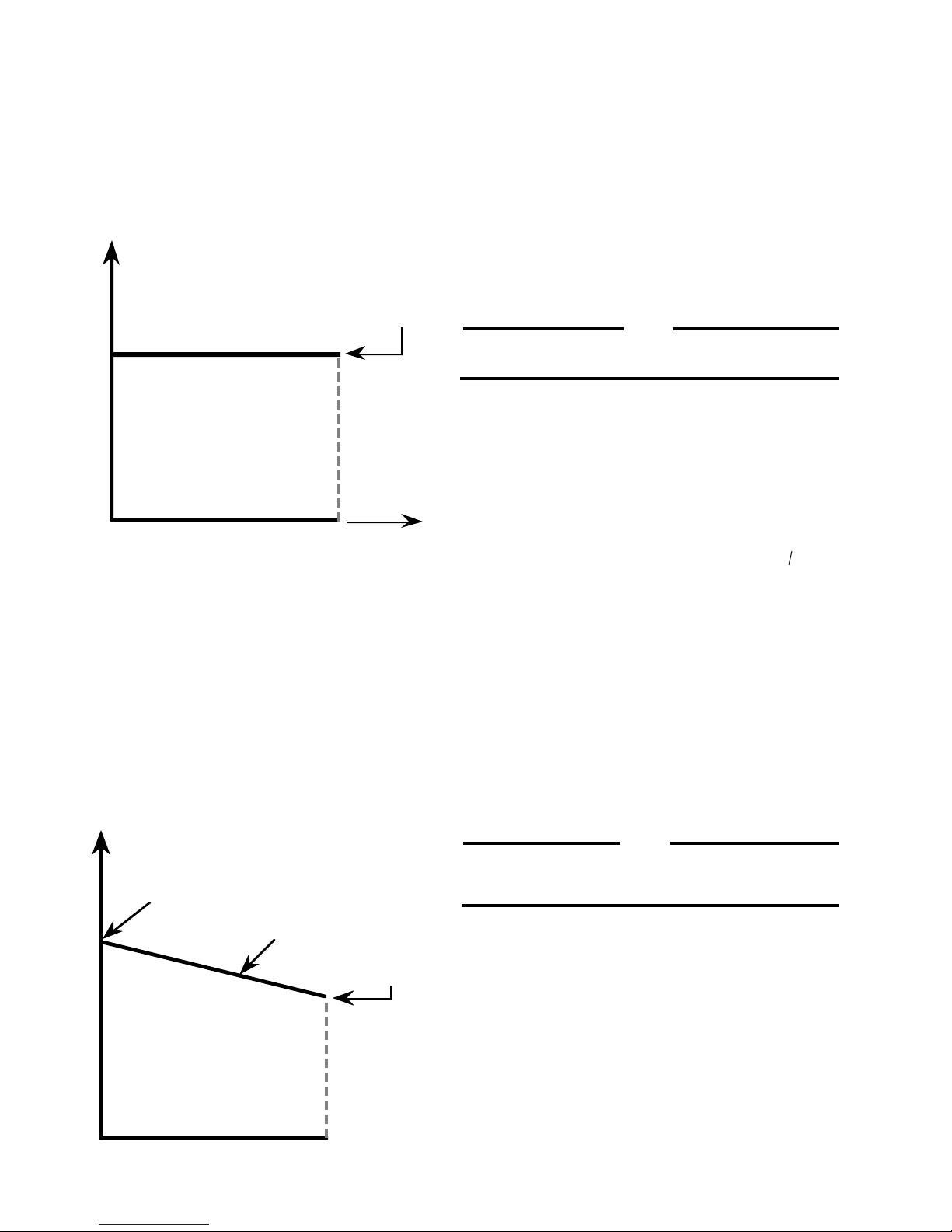
3.5 ISOCHRONOUS OPERATION
3.7 REMOTE SPEED ADJUSTMENT
Isochronous operation is obtained by setting droop potentiometer fully counterclockwise. The DYNA governor is all electric,
and it is normally operated in the isochronous mode; i.e.,
engine RPM is constant (±0.25%) under steady state load
conditions, up to the engine's maximum capability, regardless
of load on the engine.
Desired
Engine RPM
Engine
RPM
Isochronous
Operation Mode
Engine Load
100%
An optional remote speed selector (DYNS-10000) is available
for adjusting engine RPM from up to 90 meters (300 ft.) from the
engine. See the Electrical Wiring Schematic. The potentiometer can be connected for a narrow (fine) or wide speed range
control.
4. INSTALLATION
4.1 PROCEDURE
4.1.1 Mount the actuator on a suitable rigid steel bracket or
plate.
NOTE
Mounting information and kits are usually available for
a particular engine. Contact Sales Representative.
4.1.2 Set up the linkage and rod end bearings (see 4.2).
4.1.3 Install the speed sensor with SAE threads (magnetic
pickup)*.
*Magnetic pickups with metric threads are available.
Thread — M16 x 1.5 — 6 g. Tap Drill Size — 14.5 0 mm.
3.6 DROOP OPERATION
Droop operation is obtained by setting the droop potentiometer. Clockwise increases the droop. The amount of droop for
a given setting depends on the magnetic pickup frequency
and no load to full load actuator shaft rotation. A droop
potentiometer setting of 10 o'clock will give about 4% droop,
no load to full load when the pickup frequency is 4260 Hz and
actuator shaft rotation is approximately 30 degrees from no
load to full load. Lower pickup frequency or smaller shaft
rotation results in less droop for the system.
No Load
Engine RPM
Adjustable
Full Load
Engine RPM
Engine
RPM
4.1.3.1 Remove the inspection cover over the ring gear teeth.
The teeth should be free of burrs, excessive grease or dirt.
4.1.3.2 The magnetic pickup should not be installed in inspection covers. Inspect the ring gear housing and pick a location
where a 37/64" hole can be drilled such that the ring gear teeth
will pass in front of the pickup pole face. After the 37/64" hole
is drilled, use a 5/8-18 starting tap to cut threads for the
magnetic pickup, then run a bottom tap through the hole.
NOTE
The tapped hole should be drilled as nearly perpendicular
as possible over the center of the ring gear teeth.
4.1.3.3 Manually rotate the ring gear until a tooth face is directly
in the center of the tapped hole. Gently turn the magnetic pickup
clockwise into the hole until it bottoms on the tooth, and back off
1/4 turn. Tighten the jam nut firmly, maintaining the 1/4 turn
position.
0%
% of Engine Load
100%
6
 Loading...