

Barbeques Galore Ge3bsslp Owner's Manual
Owner’s Manual
GE3BSSLP
GE3BSSNG
GE4BSSLP
GE4BSSNG
n
WARNING:
All barbecues and carts are designed for outdoor use only!
All barbecues are not intended for commercial use.
n
WARNING:
Read this Owner’s Manual carefully and
be sure your gas grill is properly assembled, installed and maintained. Failure
to follow these instructions could result
in serious bodily injury and/or property
damage. This gas grill is intended for
outdoor use only and is not intended to
be installed in or on recreational vehicles or boats.
Note to Installer: Leave this Owner’s
Manual with the consumer after delivery
and/or installation.
Note to Consumer: Leave this Owner’s
Manual in a convenient place for future
reference.
Design Certified
Unit approved by
CSA Laboratories under standard
ANSI Z21-58b-2002/CGA 1.6b-2002
Customer Service Helpline: If you have questions about assembly or grill operation, or if there are damaged or
missing parts when you unpack this unit from the shipping box, call us Monday through Friday at 1-800-752-3085
RV 021705 P/N P80151005A
America's Barbecue Grill Superstores
2
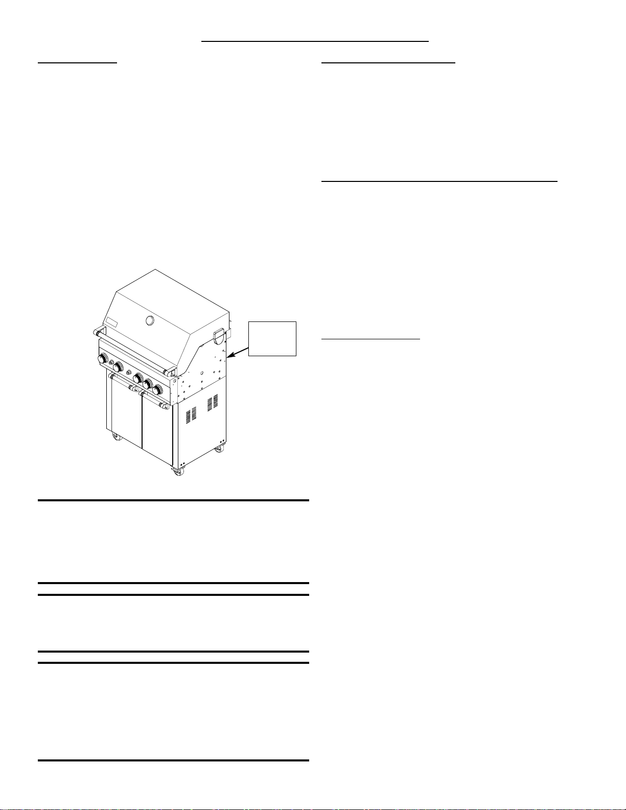
Gas Pressure
The Propane Gas Grills (Models GE(3/4)BSSLP) are
designed to operate on propane at a gas pressure regulated
at 11" water column (W.C.) when equipped with the correct
Propane Orifices on the valves and a Propane Regulator
on the supply line.
The Natural Gas Grills (Models GE(3/4)BSSNG) are
designed to operate on Natural Gas at a gas pressure regulated at 4" water column (W.C.) when equipped with the
correct Natural Gas Orifice on the valves and a Natural
Gas Regulator on the supply line.
If unsure of the type of gas your barbecue is set-up for,
refer to the rating label located on the rear of the barbecue
head (see illustration below).
n
WARNING
Fuels used in gas or oil-fired appliances and the products of
combustion of such fuels, contain chemicals known to the
State of California to cause cancer, birth defects and/ or
other reproductive harm.
This warning is issued pursuant to California Health &
Safety Code Sec. 25249.6.
n
WARNING
Failure to comply with these instructions could result in a
fire or explosion that could cause serious bodily injury,
death, or property damage.
n
WARNING
Your grill will get very hot. Never lean over the cooking
area while using your grill. Do not touch cooking surfaces,
grill housing, grill lid or any other grill parts while the grill is
in operation, or until the grill has cooled down after use.
Failure to comply with these instructions may result in
serious bodily injury.
Grill lnstallation Codes
This gas grill must be installed in accordance with all
local codes. In areas without local codes, follow the latest
edition of the National Fuel Gas Code ANSI Z223.1. In
Canada, installation must conform to standard CAN/CGA
1b149.1 or 1-b149. 2 (Installation Code for Gas Burning
Appliances and Equipment) and all local codes.
Proper Placement and Clearance of Grill
Never use your gas grill in a garage, porch, shed,
breeze way or any other enclosed area. Your gas grill is to
be used outdoors only, at least 16 inches from the back
and 14 inches to the side of any combustible surface. Your
gas grill should not be placed under any surface that will
burn. Do not obstruct the flow of ventilation air around the
gas grill housing.
This outdoor gas grill is not intended to be installed in
or on recreational vehicles and/or boats.
Propane Models:
Correct LP Gas Tank Use
LP gas grill models are designed for use with a standard
20 lb. Liquid Propane Gas (LP gas) tank, not included with
grill box. Never connect your gas grill to an LP gas tank that
exceeds this capacity. A tank of approximately 12 inches in
diameter by 18-1/2 inches high is the maximum size LP gas
tank to use. A Propane tank with an OPD (Overfill Prevention
Device) must be used. This safety feature prevents the tank
from being over-filled which can cause malfunction of the LP
gas tank, regulator and/or grill.
The LP gas tank must be constructed and marked in
accordance with specifications of the U.S. Dpt. of
Transportation (DOT). In Canada, the LP gas tank must
meet the Canadian Transportation and Communications
(CTC) specifications. Also be sure to read and follow all LP
instructions on the following page.
If the outdoor cooking gas appliance is not in use, the
gas must be turned off at the supply cylinder.
(a) Do not store a spare LP-gas cylinder under or near
this appliance;
(b) Never fill the cylinder beyond 80 percent full; and
(c) If the information in (a) and (b) is not followed
exactly, a fire causing death or serious injury may
occur.
1. The LP gas tank has a shutoff valve, terminating in an
LP gas supply tank valve outlet, that is compatible with
a Type 1 tank connection device. The LP gas tank must
also have a safety relief device that has a direct communication with the vapor space of the tank.
2. The tank supply system must be arranged for vapor
withdrawal.
CSA label
located at
rear of unit
READ THESE SAFETY
INSTRUCTIONS

3
3. The LP gas tank used must have a collar to protect the
tank valve.
Never connect an unregulated LP gas tank to your gas
grill. The gas regulator assembly supplied with your gas
grill is adjusted to have an outlet pressure of 11" water
column (W.C.) for connection to an LP gas tank.
Only use the regulator and hose assembly supplied with
your gas grill. Replacement regulators and hose assemblies must be those specified by manufacture.
Have your LP gas tank filled by a reputable propane gas
dealer and visually inspected and re-qualified at each
filling.
Never fill the gas tank beyond 80% full. Have your
propane gas dealer check the release valve after every
filling to ensure that it remains free of defects.
Always keep LP gas tanks in an upright position.
Do not store (or use) gasoline or other flammable
vapors and liquids in the vicinity of this gas grill.
An LP gas tank that is not connected for use must NOT
be stored on bottom shelf or in the vicinity of this or any
other gas grill.
Do not subject the LP gas tank to excessive heat.
Never store an LP gas tank indoors. If you store your
gas grill in the garage or other indoor location, always
disconnect the LP gas tank first and store it safely outside and out of reach of children.
LP gas tanks must be stored outdoors in a well-ventilat-
ed area. Disconnected LP gas tanks must not be stored
in a building, garage or any other enclosed area.
When your gas grill is not in use the gas must be turned
off at the LP gas tank.
The regulator and hose assembly must be inspected
before each use of the grill. If there is excessive abrasion or wear or if the hose is cut, it must be replaced
prior to the grill being used again.
Keep the gas regulator hose away from hot grill surfaces
and dripping grease. Avoid unnecessary twisting of
hose. Visually inspect hose prior to each use for cuts,
cracks, excessive wear or other damage. If the hose
appears damaged do not use the gas grill. Call our service center at 1-800-752-3085.
Never light your gas grill with the lid closed or before
checking to insure the burner tubes are fully seated over
the gas valve orifices.
Never allow children to operate your grill. Do not allow
children to play near your grill.
n
WARNING
A strong gas smell, or the hissing sound of gas indicates a
serious problem with your gas grill or the LP gas tank.
Failure to immediately follow the steps listed below could
result in a fire or explosion that could cause serious bodily
injury, death, or property damage.
Shut off gas supply to the grill.
Turn the Control Knobs to the OFF position.
Open grill lid.
Get away from the LP gas tank.
Do not try to fix the problem yourself..
If odor continues or you have a fire you cannot extin-
guish, call your fire department.
Do not call near the LP gas tank because your telephone
is an electrical device and could create a spark resulting
in fire and/or explosion.
NOTE: The normal flow of gas through the regulator and
hose assembly can create a humming noise. A low volume
of noise is perfectly normal and will not interfere with operation of the grill. If humming noise is loud and excessive
you may need to purge air from the gas line or reset the
regulator excess gas flow device. This purging procedure
should be done every time a new LP gas tank is connected to your grill. For help call the Customer Service Helpline
for assistance.
Built-in Unit
s Utilizing Natural Gas
When connecting a built-in unit to the natural gas supply
in your home, please ensure the pipe joint compound is
resistant to the action of natural gas. In addition, please
observe the following:
The barbecue and its individual shut-off valve must be
disconnected from the gas supply piping system during any
pressure testing of that system at test pressures in excess
of 1/2 psi (3.5 kPa).
The barbecue must be isolated from the gas supply piping system by closing its individual
manual shut-off valve
during any pressure testing of the gas supply piping system at
test pressures equal to or less than 1/2 psi (3.5 kPa)
The barbecue is supplied from the factory equipped for
use with LP (Liquid Propane) Gas and includes a propane
gas regulator. If operation with natural gas is desired, you
must purchase a Natural Gas Model. In addition, a Natural
Gas Regulator MUST
be installed on the gas supply line
from the natural gas source.
Please remember to check all gas connections for leaks
after the piping is completed. Follow the procedure under
the heading "CAUTION: LEAK CHECKING."
4
2. Use a bottle brush with a flexible handle. Run the brush through the burner tube and inside the burner several times,
removing any debris.
3. Preferably, an air hose should be used to force air through each burner tube. The forced air should pass debris or
obstructions through the burner and out the ports.
n
WARNING
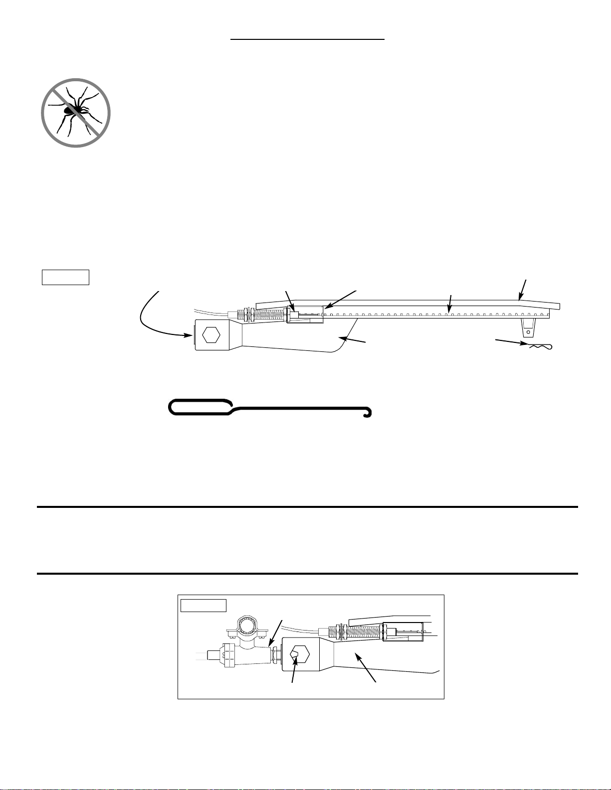
The location of the burner tube with respect to the orifice is vital for safe operation. Check to ensure the orifice is inside of
the burner tube before using your gas grill (Figure 2).
If the burner tube does not fit over the valve orifice, lighting the burner may cause explosion and/or fire.
To reduce the chance of ”FLASHBACK”, clean the burner tubes and burners before fully assembling your grill. Remove
the Retainer Clip at the rear of the burner. Carefully lift each burner up and away from the gas valve orifice, then refer to
Figure 1 and perform one of these three cleaning methods:
1. Bend a stiff wire, (a lightweight coat hanger works well) into a small hook as shown below. Run the hook through the
burner tube and inside the burner several times to remove any debris.
Figure 2
GAS VALVE
ASSEMBLY
BURNER TUBE
ORIFICE
Figure 1
SPARK ELECTRODE
ASSEMBLY
BURNER
TUBE
RETAINER
CLIP
BURNER
PORTS
BURNER
GAS COLLECTOR
BOX
TO CLEAN BURNER TUBE
INSERT HOOK HERE
n
CAUTION: BEWARE OF FLASHBACK
CAUTION: Spiders and small insects occasionally spin webs or make nests in the grill
burner tubes during transit and warehousing. These webs can lead to a gas flow
obstruction which could result in a fire in and around the burner tubes. This type of fire
is known as a ”FLASHBACK” and can cause serious damage to your grill and create
an unsafe operating condition for the user.
Although an obstructed burner tube is not the only cause of ”FLASHBACK”, it is the most common cause.
To reduce the chance of ”FLASHBACK”, you must clean the burner tubes before assembling your grill, and at least once a
month in late summer or early fall when spiders are most active. Also perform this burner tube cleaning procedure if your
grill has not been used for an extended period of time.
Before Using Your Grill
5
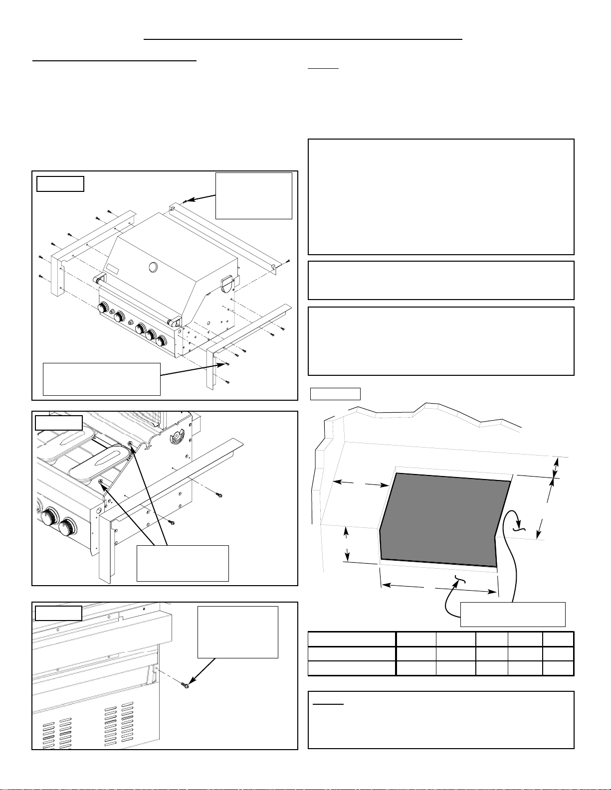
Built-in T
rim Kit Installation:
Prior to installing unit, side and rear trims must be
installed to fully support the unit.
Carefully remove the stainless steel trim pieces from the
carton and attach Left, Right & Rear stainless trims to left,
right & rear sides of barbecue using 10 bolts & 2 nuts. Check
to make sure they are aligned flush with the side barbecue
face and top before fully tightening the bolts.
NOTE:
When choosing a location for your Gas grill, keep in
mind that it should not be located under any overhead combustible construction. The side and bottom of the grill
should not be any closer than 14 inches to combustible
construction, and the back of the grill should not be any
closer than 16 inches to combustible construction.
n
WARNING
Failure to comply with these instructions could result in a
fire or explosion that could cause serious bodily injury,
death, or property damage.
Figure 3
1/4”-20 x 1/2” Phillips
Head Screw (12 ea.)
3/16” x 1/4”
Phillips Head
Screw (2 ea.)
1/4” Flange Nut
(4 ea.)
Figure 4
3/16” x 1/4”
Phillips Head
Screw (2 ea.)
Figure 5
Rear view of barbecue
Outdoor BBQ Built-in Installation Specifications
C
B
D
E
A
Model A B C D E
GE3BSSLP/NG 10-1/4" 28-3/4" 23" 14" 16"
GE4BSSLP/NG 10-1/4" 36-5/8" 23" 14" 16"
non-combustible
construction
Figure 6
nWARNING
Vapors from products containing Chlorine and other caustic chemicals can cause Stainless Steel flexible connectors
to corrode. THESE PRODUCTS SHOULD NOT BE
STORED IN AN ISLAND OR NEAR THE connector.
Cleaning solutions, Household Chemicals and Solder fluxes can also cause pinholes if they come in contact with
these connectors and MUST be washed off immediately
with water.
NOTE: Upper & lower ground-level vents (20 sq. in. minimum each) MUST BE PROVIDED for combustion air on
both sides of built-in construction. Please ask a Barbeques
Galore associate for full details.
Barbecues must be installed in accordance with CSA
specifications and all local building codes.
6
Non-combustible
Construction
Vented on
BOTH SIDES
of Island
Vented
Access Door
Figure 9
n
WARNING
When using Propane, EXTREME CAUTION should be
used to provide ample ventilation of vapor from the enclosure. LP Gas vapor is heavier than air and SERIOUS
INJURY from a DANGEROUS EXPLOSION could occur if
LP Gas is allowed to accumulate in an enclosure and then
ignited. Both the Barbecue enclosure and LP cylinder
enclosure require venting that must be provided at the floor
level of the enclosure to allow any leaking LP Gas vapor to
escape. Upper & lower ground-level vents (20 sq. in. minimum each) MUST BE PROVIDED on both sides of builtin construction. Please ask a Barbeques Galore associate
for full details.
NOTE: When installing a barbecue equipped for liquid
propane in an island, the propane tank must be in a separate enclosure that is completely isolated from the barbecue. It must be cross-ventilated in accordance with the current standard. The propane tank MUST NEVER be
installed directly under the barbecue.
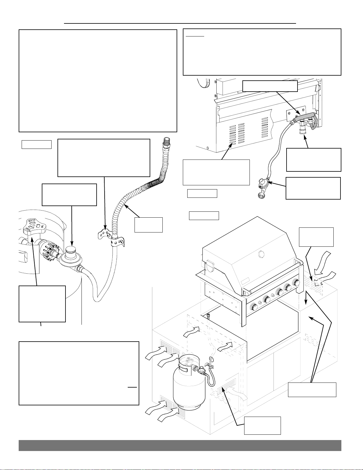
Outdoor PROPANE BBQ Built-in Installation Specifications
n
WARNING
Failure to comply with these instructions
may result in a fire or explosion that
could cause property damage, serious
bodily injury or death. This gas grill is
intended for outdoor use only and is not
intended to be installed in or on recreational
vehicles or boats.
Questions? Call our Grill Information Center: 1-800-752-3085 Monday thru Friday 8:00 am - 4:30 pm PST
Secure Stainless Flexline with
Plumber’s Tape to prevent shifting
during tank installation. An
approved rubber gas hose is then
connected to the LPG tank.
LP Tank must
have a QCC-1
Type connection
with OPD
(not included)
CSA Approved
Propane Regulator
& hose assembly
Stainless
Flexline
CSA Approved
Propane Regulator
& hose assembly
Rear Gas Manifold
Side Burner
Connection Quick
Disconnect Socket
Air vents at rear of BBQ
must remain unobstructed
to allow for combustion air.
Figure 8
Figure 7
7
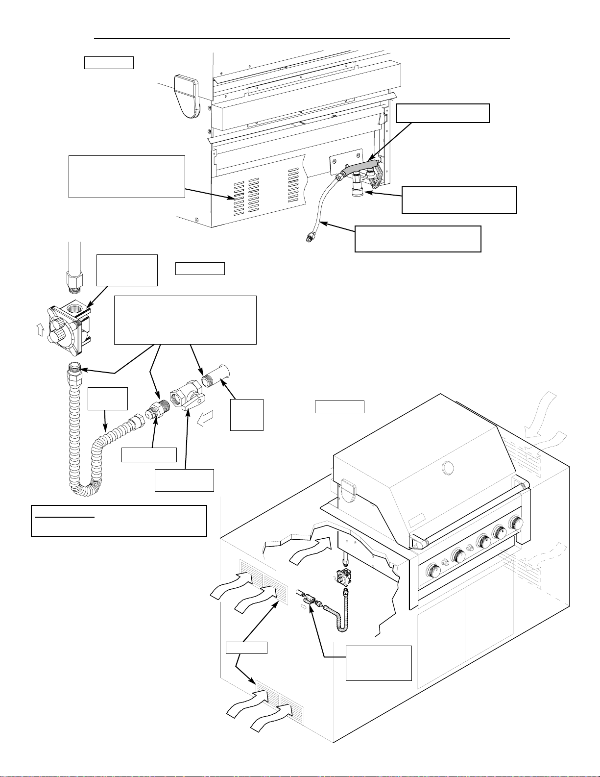
Air Vents
Access must
be provided to
Shut-off Valve
CSA Approved
Natural Gas
Regulator
Stainless
Flexline
Natural
Gas
Supply
Shut-off Valve
1/2-1/2” NPT
Close Nipple
Yellow Teflon Pipe Thread
Sealant is recommended for
use on all pipe thread connections EXCEPT flared threads.
IMPORTANT: Regulator must be on
the Barbecue or your warranty is void.
IN
OUT
Outdoor NATURAL GAS BBQ Built-in Installation Specifications
Important Note: This grill is manufactured to exact specifi-
cations. LP models are certified for use with LP gas and NG
models are certified for use with Natural Gas. You cannot
convert this grill from one fuel type to the other. For your
safety, conversion kits are available but can only be installed
by a BBQ Galore technician. Any attempt to convert your grill
will void your warranty.
Figure 10
Figure 11
Figure 12
Air vents at rear of BBQ
must remain unobstructed
to allow for combustion air.
Natural Gas pre-assembly
connection tube (1/2” NPT)
Rear Gas Manifold
Side Burner Connection
Quick Disconnect Socket
8
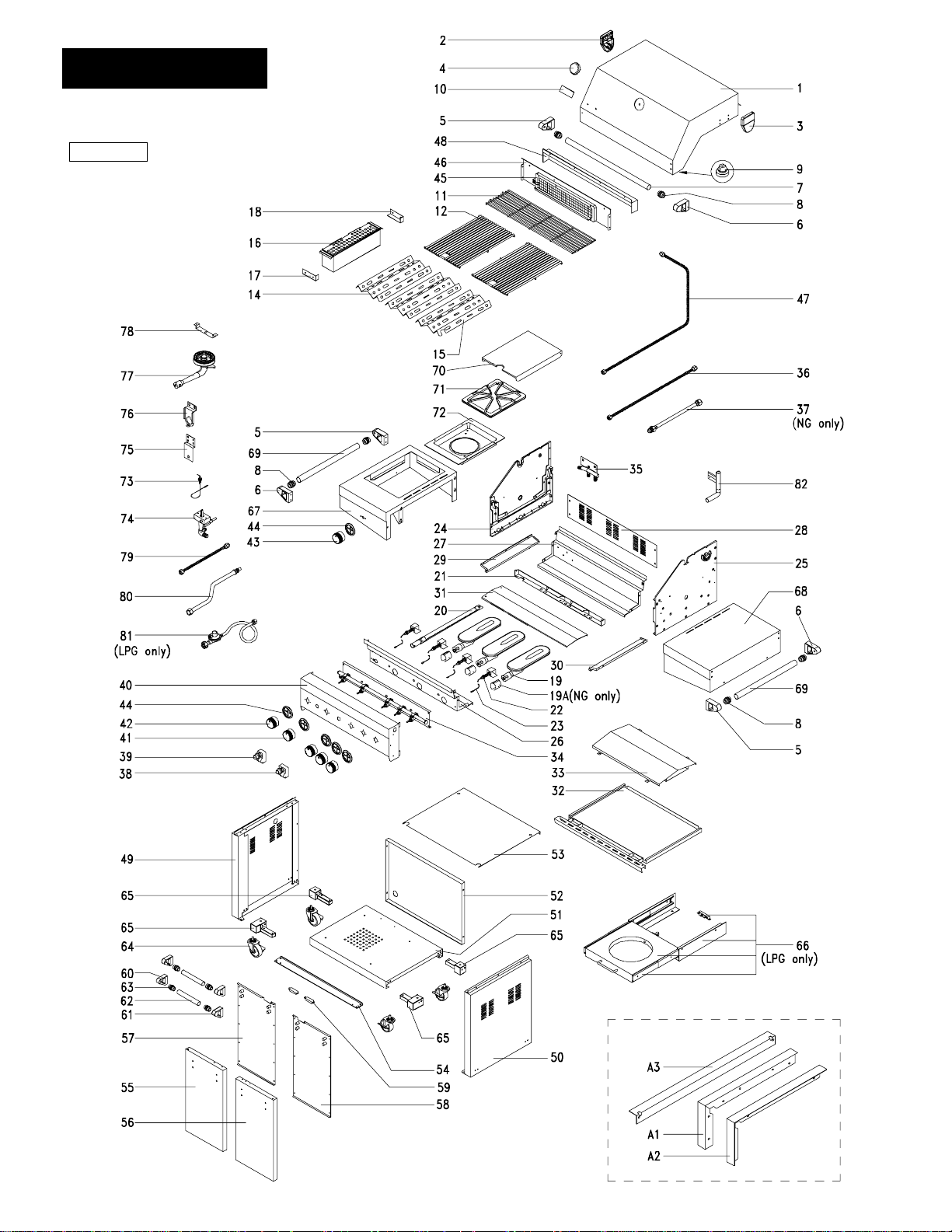
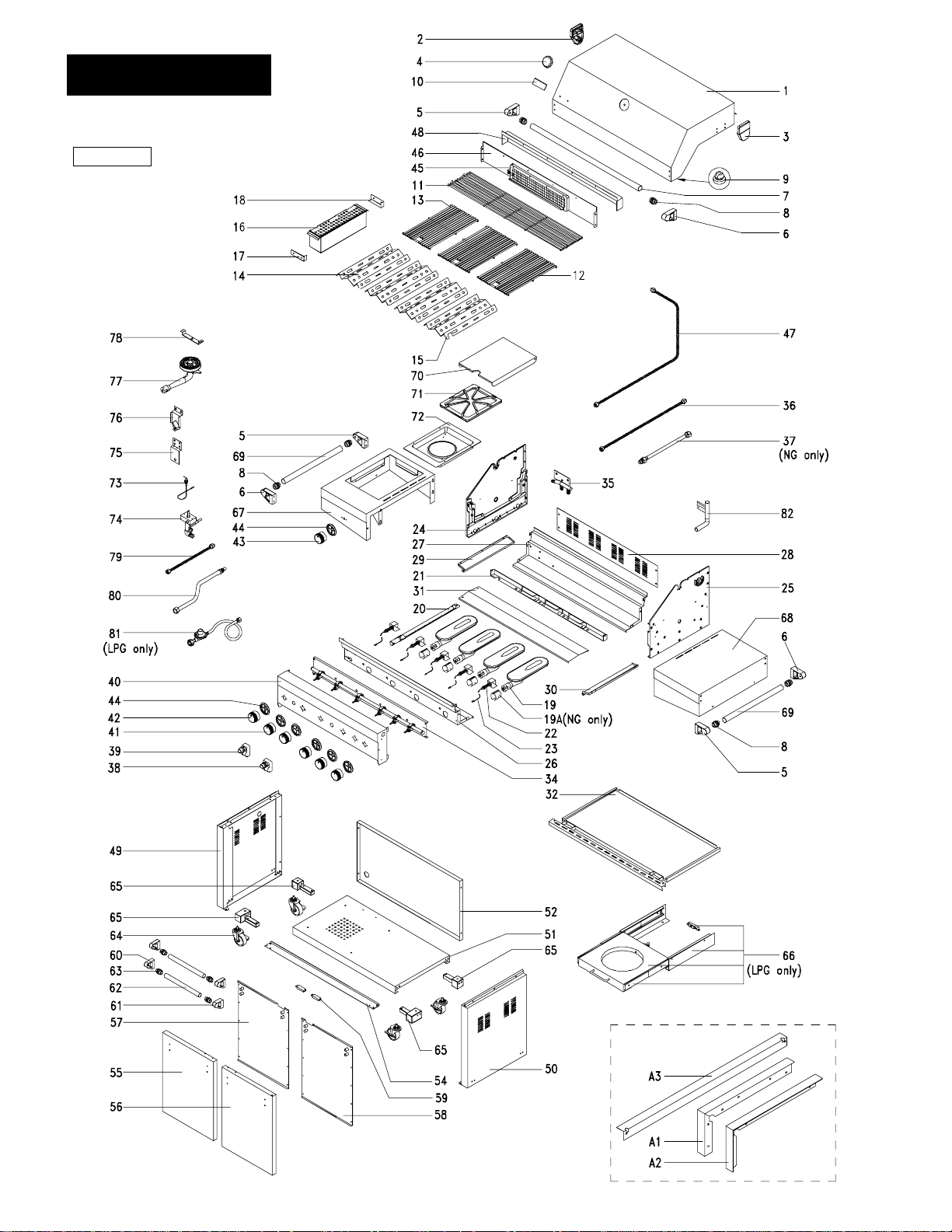
PARTS DIAGRAM
MODELS:
GE3BSSLP, GE3BSSNG
Figure 13
9
PARTS DIAGRAM
MODELS:
GE4BSSLP, GE4BSSNG
Figure 14

1
2
3
4
5
6
7
8
9
10
11
12
13
14
15
16
17
18
19
19A
20
21
22
23
24
25
26
27
28
29
30
31
32
33
34
35
36
37
38
39
40
41
42
43
44
45
Lid
Lid Hinge Support, Left
Lid Hinge Support, Right
Temperature Gauge
Handle Bracket, Left
Handle Bracket, Right
Lid Handle
Handle Heat-Insulating Spacer,Lid/Cart
Protective Pad
Name Plate
Cooking Rack/Secondary
Cooking Grid/Large
Cooking Grid/Small
Flame Tamer/Stainless Steel
Flame Tamer/Stainless Steel
Smoker Drawer
Smoker Drawer Bracket,Front
Smoker Drawer Bracket,Rear
Burner/Main
Burner Air Shutter/Main (NG only)
Smoker Burner
Burner Bracket
Gas Collector Box with Electrode
Electric Wire Set
Bowl Panel, Left
Bowl Panel, Right
Bowl Panel, Front
Bowl Panel, Rear
Bowl Wind Shield
Grease Tray Track, Left
Grease Tray Track, Right
Grease Tray Heat Shield, Upper
Grease Tray
Grease Tray Heat Shield, Lower
Gas Valve/ Manifold Assembly (LPG)
Gas Valve/ Manifold Assembly (NG)
Rear Gas Manifold
Gas Manifold Extension Tube
Connection Tube (NG only)
Electric Ignitor, 4-Ports
Electric Ignitor, 2-Ports
Control Panel
Control Knob with Rubbert Ring for Main Burner
Control Knob with Rubbert Ring for Back/Smoker Burner
Control Knob with Rubbert Ring for Side Burner
Control Knob Seat
Back Burner Assembly (LPG)
Back Burner Assembly (NG)
Y0110020
P03320003K
P03320004K
P00601171A
P00301026E
P00302026E
P00205044B
P06801008A
P05518002I
P00407004C
P01515003B
P01604001B
P01708001B
P01708002B
P06701006A
P06703001A
P06703002A
P02001062E
P05524006A
P02008002A
P02213012B
P02609004B
P02615016A
P00705087G
P00706087G
P0073809BC
P0072517BC
P0071606FC
P05330001E
P05330002E
P06904006C
P02705104A
P06903017A
Y0060143
Y0060144
P05315001E
P03715004A
P03705042E
P02502024C
P02502012C
P02908071B
P03411153L
P03411163L
P03411173L
P03415024A
Y0030012
Y0030013
1
1
1
1
3
3
1
6
2
1
1
2
2
1
1
1
1
3
3
1
1
4
1
1
1
1
1
1
1
1
1
1
1
1
1
1
1
1
1
1
1
3
2
1
6
1
1
Y0110021
P03320003K
P03320004K
P00601171A
P00301026E
P00302026E
P00205045B
P06801008A
P05518002I
P00407004C
P01517002B
P01604001B
P01604003B
P01708001B
P01708002B
P06701006A
P06703001A
P06703002A
P02001062E
P05524006A
P02008002A
P02213024A
P02609004B
P02615017A
P00705087G
P00706087G
P00738096C
P0072519BC
P0071608FC
P05330001E
P05330002E
P06904003C
P0270605CC
Y0060147
Y0060148
P05315001E
P03715004A
P03705042E
P02502024C
P02502012C
P02910071B
P03411153L
P03411163L
P03411173L
P03415024A
Y0030012
Y0030013
1
1
1
1
3
3
1
6
2
1
1
2
1
3
1
1
1
1
4
4
1
1
5
1
1
1
1
1
1
1
1
1
1
1
1
1
1
1
1
1
1
4
2
1
7
1
1
PARTS LIST
ITEM
DESCRIPTION
P/N
GE3BSS
P/N
GE4BSS
QTY
GE3BSS
QTY
GE4BSS
10

PARTS LIST 2
46
47
48
49
50
51
52
53
54
55
56
57
58
59
60
61
62
63
64
65
66
67
68
69
70
71
72
73
74
75
76
77
78
79
80
81
82
A1
A2
A3
---
Back Burner Frame
Back Burner Extension Tube
Back Burner W ind Shied
Cart Side Panel, Left
Cart Side Panel, Right
Cart Bottom Shelf
Cart Rear Panel
Cart Top Panel
Door Bracket
Door,Left
Door,Right
Door Trim Plate,Left
Door Trim Plate,Right
Door Magnet
Door Handle Bracket,Left
Door Handle Bracket,Right
Door Handle
Door Handle Heat-Insulating Spacer
Caster, 2.5 in., w. Brake
Caster Seat Set
Tank Pull-Out Tray Assembly (LPG only)
Side Burner Frame
Side Shelf, Right
Side Shelf Handel
Side Burner Lid
Side Burner Pot Support
Side Burner Body
Side Burner Electrode
Side Burner Gas Valve Assembly (LPG)
Side Burner Gas Valve Assembly (NG)
Side Burner Gsa Valve Jet Mounting Bracket
Side Burner Mounting Bracket
Side Burner with Brass Ring
Side Burner Bracket
Side Burner Connection Tube
Side Burner Connection Hose
Regulator with Hose/LPG
Lighting Tube
Trim Panel, Left
Trim Panel, Right
Trim Panel, Rear
Owner s Manual
P02011005E
P03701001A
P06906004C
P07602005A
P07603002A
P01007003C
P07701013A
P01007004C
P03302004C
P04302013A
P04303016A
P07506003A
P07507003A
P05523002K
P00301036E
P00302036E
P00205047B
P06801009A
P05118001E
Y0260018
Y0340024
P01108005B
P01107005B
P00205046B
P00115106A
P00815005D
P02301010B
P02607004C
Y0060151
Y0060152
P03317001C
P0221506CA
P02002010G
P02215045A
P03701005A
P03705005I
P03601011A
P05507002A
P07505003A
P07504003A
P07515011A
P80151005A
P02011007E
P03701002A
P06906008C
P07602005A
P07603002A
P01009001C
P07701014A
P03302008C
P04302014A
P04303017A
P07506004A
P07507006A
P05523002K
P00301036E
P00302036E
P00205048B
P06801009A
P05118001E
Y0260018
Y0340024
P01108005B
P01107005B
P00205046B
P00115106A
P00815005D
P02301010B
P02607004C
Y0060151
Y0060152
P03317001C
P0221506CA
P02002010G
P02215045A
P03701005A
P03705005I
P03601011A
P05507002A
P07505003A
P07504003A
P07515012A
P801510005A
1
1
1
1
1
1
1
1
1
1
1
1
1
2
2
2
2
4
4
1
1
1
1
2
1
1
1
1
1
1
1
1
1
1
1
1
1
1
1
1
1
1
1
1
1
1
1
1
1
1
1
1
1
1
2
2
2
2
4
4
1
1
1
1
2
1
1
1
1
1
1
1
1
1
1
1
1
1
1
1
1
1
1
PARTS LIST
ITEM
DESCRIPTION
P/N
GE3BSS
P/N
GE4BSS
QTY
GE3BSS
QTY
GE4BSS
11
 Loading...