

Page 1
DIRECTIONS FOR USE
INSTALLATION INSTRUCTIONS
ECO
40 / 52 / 55
EN -13240
NAME OUTPUT DESCRIPTION
ECO 40 5.0 kW Stove
ECO 52 7.0 kW Stove
ECO 55 8.0 kW Stove
Page 2

Page 3
3
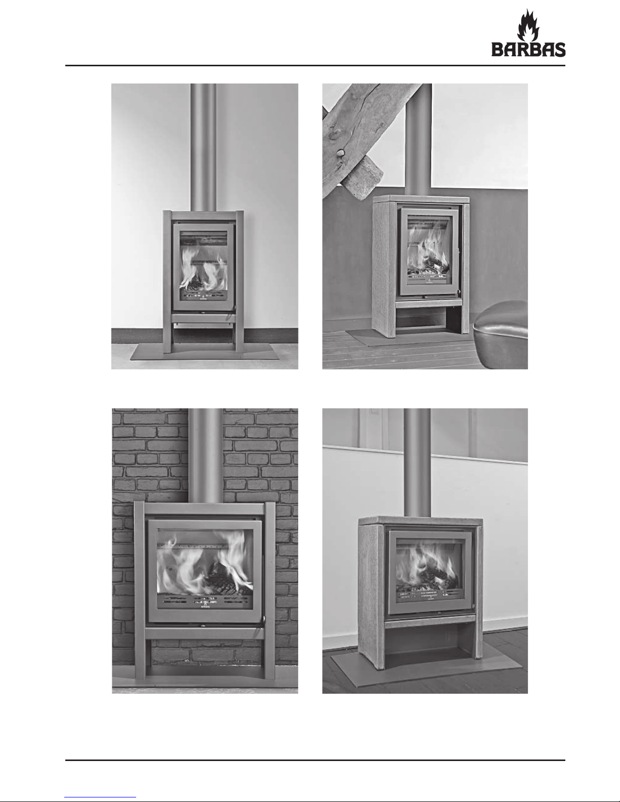
ECO 40 / 52 / 55
ECO 40 Steel
Floor plate and wood rack (high model) are optional !
ECO 52 Steel
ECO 40 Soapstone
ECO 52 Soapstone
Page 4
4
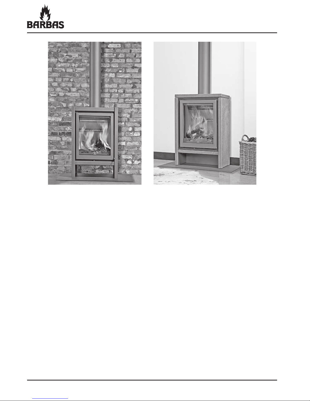
ECO 40 / 52 / 55
ECO 55 Steel ECO 55 Soapstone
Page 5
5
ECO 40 / 52 / 55
TABLE OF CONTENTS
Page
1. Introduction
1.1 Preface...............................................................
............
....
. 7
1.2 Safety.........................................................
..........
..........
.....
. 7
2. Location........................................................................
.....
.......... 10
3. Installation instructions........................................
...............
.....
.... 16
4. Operation of the stove.........................
.......
.....................
............ 30
5. Stoking up for the fi rst time.............................................
.............
31
6. Use
6.1 Ventilation................................................
.........................
... 32
6.2 Getting the fi re going..................................................
.
.......
. 32
6.3 While stoking......................................................................
.
33
6.4 Heating economically..................................
..............
..........
. 35
6.5 Cleaning the window.........
.
........
......
.................
.................
. 35
7. General hints
7.1 Tips....................................................................
...........
....... 36
7.2 Output...............................................................
.
....
....
....
.....
. 37
8. Fuels.................................................................................
......
..... 39
9. Amount of fuel..........................................
.................
.............
....
. 40
10. Regular maintenance........................................
.......
...................
. 42
11. Replacement parts....................................
.......
............................ 43
12. Dimensions.................................................................................. 48
13. Technical data............................................................
................. 54
14. Frequently asked questions..............
......
.....................
.............
... 56
Page 6

6
ECO 40 / 52 / 55
Page 7
7
ECO 40 / 52 / 55
1. INTRODUCTION
1.1. PREFACE
We would like to congratulate you on your purchase of this modern BARBAS
stove. This quality product will give you years of heating pleasure as you enjoy
the play of the • ames and the cosy glow of the • re.
This manual contains directions for both positioning the appliance and for its
environmentally-friendly use. It also contains technical data for the appliance,
parts information and directions in the event of problems. Study this manual
carefully before using the stove. We recommend you keep this manual in a safe
place for reference purposes.
The Unilux-3 40 is recommended for exemption under Section 21 of the Clean
Air Act 1993 and is therefore allowed to be used in smokeless zones / smoke
control areas.
1.2. SAFETY AND INSTALLATION INSTRUCTIONS
Safety
• Do not place • ammable objects within 80 cm of the appliance. Pay special
attention to furnishings and ornaments around the stove.
• To ensure safe operation, the following minimum distances must be
maintained between the appliance and any existing side or rear wall
(temperature ≤ 80 °C).
ECO 40 : in respect of side wall : Distance ≥ 10 cm
ECO 40 : in respect of rear wall : Distance ≥ 10 cm
ECO 52/55 : in respect of side wall : Distance ≥ 10 cm
ECO 52/55 : in respect of rear wall : Distance ≥ 20 cm
• If the • oor is • ammable, a non• ammable • oor plate should be used under
the appliance. Use the • oor plate as mentioned in chapter 2.2.
• When you use your stove, the exterior will become hot. Always wear the
glove or use the accessories supplied when • lling etc. Protect yourself
and others (especially children!) from burns. Do not leave children
unattended when the stove is burning.
Page 8

8
ECO 40 / 52 / 55
• Watch your clothing. Synthetic clothing in particular can easily catch fi re and
burn intensely.
• Do not approach the appliance with fl ammable materials or liquids. Any work
with solvents, adhesives etc. in the space heated by the stove can be very
dangerous.
• Make sure you know what state your chimney is in. Cracks in the chimney
may not only lead to damp, staining of walls and leaking of smoke, they can
also impair the carrying off of smoke. Make sure you get proper advice from
your Barbas dealer or other specialist company.
• Avoid chimney fi res!
Have your chimney swept at least once per year - more often if you use your
stove a lot.
Prevent excessive deposits of soot inside the chimney by not burning
freshly-cut wood. Instead, burn clean, dry chopped wood.
• Do not use your stove as a barbecue. This can cause (fl ammable) fat
deposits to be left in the chimney and hastens the chimney becoming
clogged. Prevent your chimney being soiled from above (birds’ nests etc.) by
fi tting a suitable cap to the chimney pot.
• Follow the instructions issued by your local fi re brigade.
The stove can be taken in operation if national and local regulations are
satisfi ed. The required constructive adaptations should be satisfi ed as well.
Installation Instructions
• Wood and wood bricks can be burned in the stove.
Coals can’t be burned in the stove.
• Never use the stove to burn rubbish.
• Read all instructions/stickers, on and around, the appliance.
• Carefully read the user manual before using your appliance for the fi rst time.
When you fi rst fi re up your appliance, there are a number of extra points you
should take into account. See section 5.
Page 9

9
ECO 40 / 52 / 55
• Never use liquid fuels, such as petrol, lighter ! uid etc.
Use of these could cause dangerous situations and damage your appliance.
• In transit, some parts of the appliance may have moved from their original
place. Check that the door opens and closes, the brake plate is " tted
correctly to the brackets at the top of the " re, the internal panels are " xed to
the walls and the stones on the bottom have not moved. Check whether the
grate is lying correctly and there are no foreign objects in the ashtray.
• Avoid over-loading (white burning glow), caused, for example, by lengthy
burning with primary air (combustion air supply slider all the way to “ + ”)
or by burning too much wood in one go. The stove can then become overheated.
This may damage the grate and the metal ! ue gas ! ap.
• Consult the current local building regulations before starting the assembly.
Page 10

10
ECO 40 / 52 / 55
2. LOCATION
2.1. INCLUDED
Set - Warranty
documentation - Manual
- Connection ring (cast iron) + Cord
Smoke - Sealing plate + Cord
connection set (for the top of the stove)
In the (If the appliance - Rosette, Steel
appliance is ordered with a (if soapstone version)
rear-connection) - Coverplate, Steel
(if steel version)
Attributes
- Glove (Heat resistant up to max. 95°C)
- Operating hook / Poker
- Top plate with through-feed hole,
Soapstone
- Rosette, Steel (if • ue outlet
rear-connection)
Soapstone - Left side panel, Soapstone
- Right side panel, Soapstone
- Small front panel, Soapstone
- Foot, Steel
Type
- Complete exterior, Steel
Steel
- Cover plate, Steel (if • ue outlet
rear-connection)
(Factory assembled)
N.B. If any part is missing, please contact your dealer.
Page 11

11
ECO 40 / 52 / 55
2.2. ACCESSORIES
The following accessories can be supplied by your dealer:
Thick-walled (2 mm) steel chimney system Ø150 mm:
Description
Part no
Color
Anthracite
Gray
Duct 1000 mm
310087 l
310094 l
Duct 500 mm
310088 l
310095 l
Duct 1000 mm + valve
310180 l
310186 l
Elbow 90°
310093 l
310100 l
Elbow 45°
310091 l
310098 l
Elbow 30°
310090 l
310097 l
Support sleeve, double-walled 302226
- -
Rosette
310181 l
310187 l
Accessorie
Part no
Color
Anthracite
Floor plate E ECO 40 327633 l
Floor plate F ECO 52/55 327634 l
Wood rack ECO 40 - High model - h = 60 mm 327647 l
Wood rack ECO 52 - High model - h = 60 mm 328059 l
Wood rack ECO 55 - High model - h = 60 mm 327648 l
Page 12

12
ECO 40 / 52 / 55
2.3. PREPARATION FOR POSITIONING
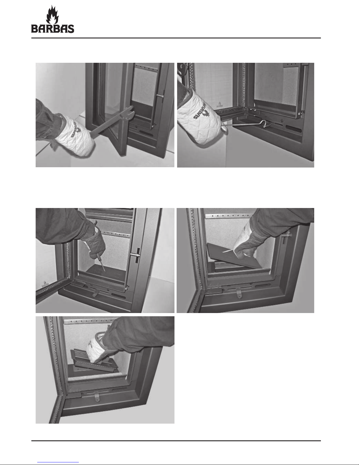
Check all functions of the stove before • tting.
• Check the opening and closing operation of the door.
‚
•
Turn the handle all the way down:
Door is locked.
This handle position should be
set when the appliance is not
in use.
Handle 30° forwards:
Door is still fully locked.
This handle position should be
used when the appliance is being
stoked. It allows the door to be
opened and closed easily.
Page 13
13
ECO 40 / 52 / 55
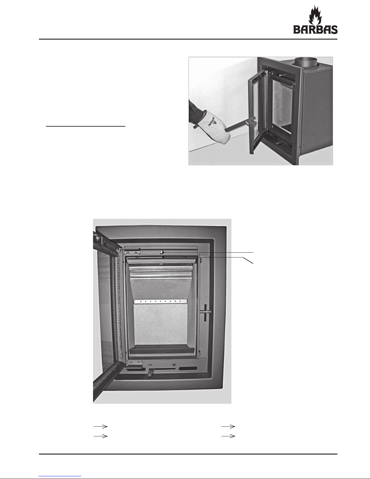
• Check the operation and setting of the • ue gas • ap.
ƒ
Flue gas • ap pin
Flue gas • ap
Door open Pin comes forwards Flue gas • ap open
Door closed Pin is pressed in by the door Flue gas • ap closed
Handle ± 50° forwards:
The door releases from its
lock and be opened forwards.
Page 14
14
ECO 40 / 52 / 55
• Check whether the ashtray is completely empty.
• Check the operation of the slider for controlling the combustion air.
Page 15

15
ECO 40 / 52 / 55
• Report any defects immediately to your dealer.
• Remove enclosed documents and components from the stove.
Have the suitability of the area in which the stove is to be placed (and the
chimney) approved by a specialist. The stove must have its own chimney,
constructed in compliance with current legislation.
Page 16
16
ECO 40 / 52 / 55
3. INSTALLATION INSTRUCTIONS
3.1. FITTING INSTRUCTIONS
When • tting the stove, local and/or national regulations relating to • re safety
must be followed. In case of doubt, consult the • re safety department of the local
• re brigade, particularly if the stove is to be • tted in a home with walls and/or
• oors containing • ammable material.
Position the appliance suf• ciently far away from the wall behind it, according
to the data from chapter 1.2. If the walls are not • re-proof, the distance should
be such that the wall in question cannot become hotter than 80°C, even when
the stove is stoked up to high temperatures. In case of doubt, insert a • re-proof
protection shield.
The • oor on which the appliance is placed must have suf• cient bearing power.
The connection of several appliances to a single • ue/chimney is not allowed.
3.2. CHIMNEY
Be sure that existing chimneys are completely air-tight and in good condition. In
terms of dimensions, the chimney must have a diameter of at least 150 mm for
the entire length (including the chimney pot).
Ensure that the chimney is • tted with an appropriate cap to avoid rain and dirt
getting in (as well as bird’s nests).
The draught • owing through the chimney determines how well your stove will
burn (recommended draught 0.15 mbar: = 15 Pa).
In the event of problems, a solution may be a different chimney cap, if necessary
one with a chimney fan. Contact a specialist if you have any doubts about any of
the above points.
If your chimney is unsuitable, or if your home does not have a chimney,
we recommend the use of double-walled stainless steel chimney sections.
Chimneys must comply with the prevailing building regulations. Make sure the
building is carried out by a specialist. When purchasing such chimneys, be sure
to check if a casing is required.
Page 17

17
ECO 40 / 52 / 55
Important:
• Chimneys must be free-standing, i.e. they must not rest on the appliance
itself.
• Any pipe connections that are not insulated must also be fully insulated.
• Flammable material must be kept clear (outside the casing/insulation zone)
of all through-feeds in the • oor or wall (remember the roof decking).
• The chimney opening must be at least 5 metres above the top of the door
opening of your appliance.
• The chimney must protrude at least 40 cm above the apex of a sloping roof
and at least 1 metre above a • at roof. In short, the chimney must always end
in an area with a negative air pressure. Contact your local chimney sweep for
the exact dimensions of the chimney opening.
Between the stove and chimney, use thick-walled smoke piping (Steel, ≥2 mm).
See Chapter 2.2.
The ! rst pipe connected to the appliance must have a diameter of 150 mm at
both ends. This will prevent any condensation from the chimney running over
the external end of the pipe. Connect the pipes to the existing chimney (ceiling)
using a sliding sleeve (niche pipe). Check all connections for air-tightness.
If there is too much draught running through your chimney (e.g. if the chimney is
long and straight in a tall building), it may be possible to insert a chimney valve
in the pipe near the appliance. Before doing this, be sure to obtain sound advice
from a specialist.
Do not make any horizontal connections. Deposits and soot will accumulate here
(unless it is a short horizontal connection directly behind the stove).
Avoid bends at all costs. The maximum deviation from the perpendicular is 45°.
The chimney calculation, as in Germany, is made according to DIN 4705 parts
1 and 2.
Page 18
18
ECO 40 / 52 / 55
The mass • ow and exhaust temperature of the stove
The mass • ow and exhaust temperature of the stove are shown in chapter 13;
Technical Data. These values are important to consider when assessing the
dimensions of the • ue to which the stove is to be connected.
Cleaning the chimney/• ue
Make sure your chimney/• ue is cleaned at least once a year by a recognized
chimney sweep.
If the chimney has a chimney valve, the free opening in the chimney valve • ap
must measure at least 12% of the surface.
3.3. AERATION / VENTILATION
A stove generates : - heating air
- combustion air
Heating air (convection air) is devoted to the convection of heat from the
appliance to the room. No other provisions are necessary. The source of heat is
in the room and stays there.
Combustion air is needed to keep the combustion going by drawing in air from
the room due to the natural draught of the chimney.
The intake opening for the air is under the door. When using the appliance,
please ensure there is a suf! cient supply of fresh air: minimum 50 cm2 (Ø80
mm) opening in the room where the stove is placed.
Make sure that the ventilation supply is open; this is particularly important with
today’s airtight dwellings.
If the dwelling has mechanical ventilation that creates under pressure in the
room where the appliance is located, it is necessary to ! t a • ue gas fan. The
type of • ue gas fan is dependent on the capacity of the mechanical ventilation
system. Always consult your ! tter about this.
In dwellings with an operating extractor hood, this should be turned to the lowest
setting or turned off altogether. If the extractor hood remains in use, additional
ventilation must be provided in compensation. This will not only avoid poor
combustion, but will also prevent • ue gases being sucked from the appliance
into the room.
Should creating an extra ventilation opening prove insuf! cient, it is then necessary to ! t a • ue gas fan.
Page 19
19
ECO 40 / 52 / 55
3.4. FITTING THE STOVE
3.4.1. Connecting the smoke outlet
The appliance can make use of either a top or rear connection Ø150 mm
(Ø148 mm external) for the • ue (chimney).
Smoke outlet top-connection
Factory assembled, the appliance is provided with a (detachable) smoke
outlet top-connection. This connection is intended for steel stovepipes, double/
single-skinned stainless steel (insulated) • ues or double/single-skinned • exible
stainless steel • ues.
Smoke outlet rear-connection
In order to be able to assemble the smoke outlet rear-connection, remove the
• ue gas • ap and the brake plate • rst.
See chapter 11 for the disassembly sequence: “Sequence for replacing the
interior of the appliance”.
Fit the sealing plate and the protective plate to the other opening.
Situate the appliance in such a way that the • ue gas outlet is precisely in line
under the chimney connection (niche pipe) in the ceiling (top connection) or with
the chimney connection (niche pipe) in the wall (rear connection).
Page 20

20
ECO 40 / 52 / 55
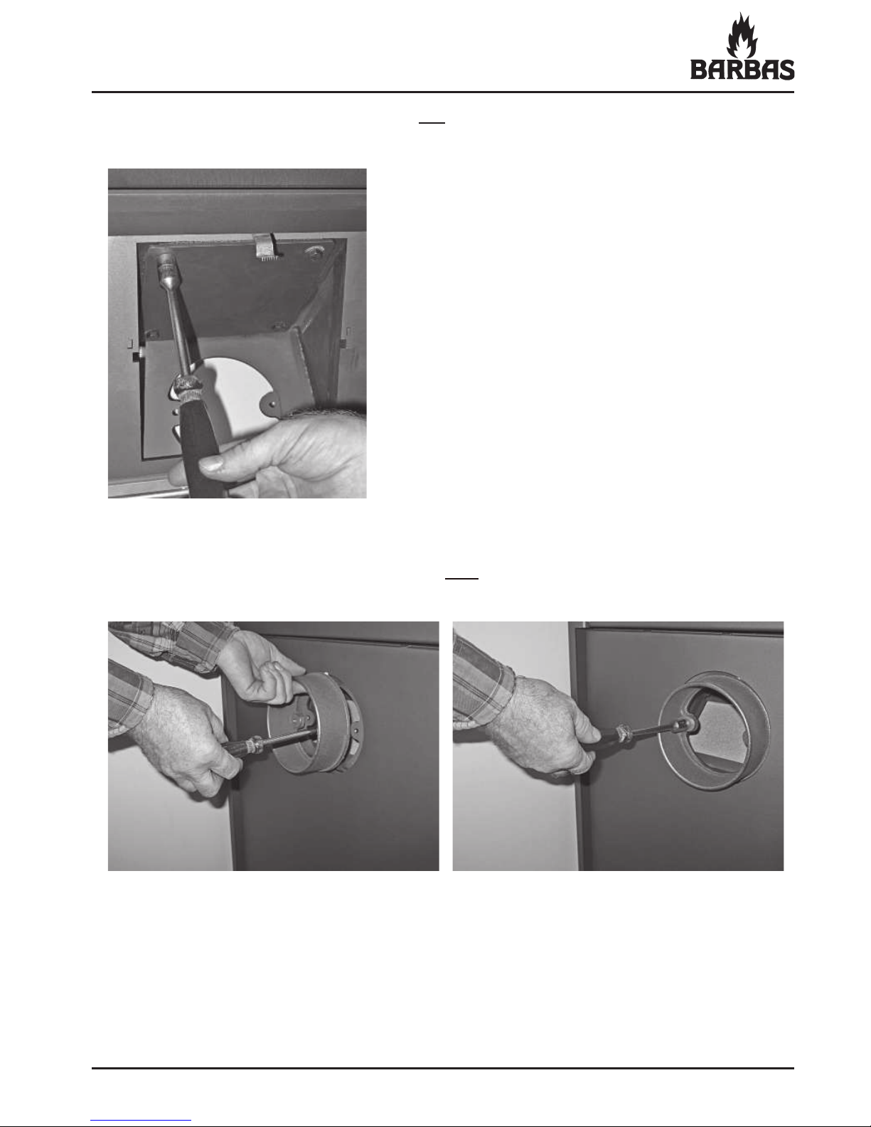
• Disassemble the sealing plate of the rear-connection by way of the inside of
the appliance.
Assemble the smoke outlet rear-connection
• Disassemble the smoke outlet top-connection.
Page 21
21
ECO 40 / 52 / 55
• Assemble the cast-iron smoke outlet rear-connection ring at the outside
of the appliance.
Attention ! : Ensure that the sealing cord
" ts properly all round.
Attention ! : Ensure that the sealing cord
" ts properly all round.
• Assemble the sealing plate of the top-connection by way of the inside of
the appliance.
Page 22

22
ECO 40 / 52 / 55
ECO 40 / 52 / 55 Steel
All steel parts are factory assembled.
Positioning the appliance
• Level the appliance by using an Allen key to set the 4 adjustable feet to the
correct height.
• Place the steel cover plate on top of the appliance, if the smoke outlet rear connection is in use.
Page 23

23
ECO 40 / 52 / 55
ECO 40 / 52 / 55 Soapstone
The “foot” and soapstone side panels (L+R), top plate and small front panel are
supplied separately.
Positioning the “foot” and appliance
• Place the “foot” where the stove will be situated.
Screw 4 adjusting screws into the top of the “foot”.
• Let the adjusting screws stick out about 13 mm above the “foot”.
Page 24

24
ECO 40 / 52 / 55
• Place the appliance carefully on the “foot”.
Check whether the appliance is aligned with the “foot” on all sides.
Adjust as necessary with the adjusting screws.
• Temporarily remove the door in order to position the appliance by lifting it
slightly and taking it off.
Page 25

25
ECO 40 / 52 / 55
• Also check whether the appliance is level with the “foot”.
Pack the foot underneath with metal plates as required.
Mounting of the soapstone and other loose parts
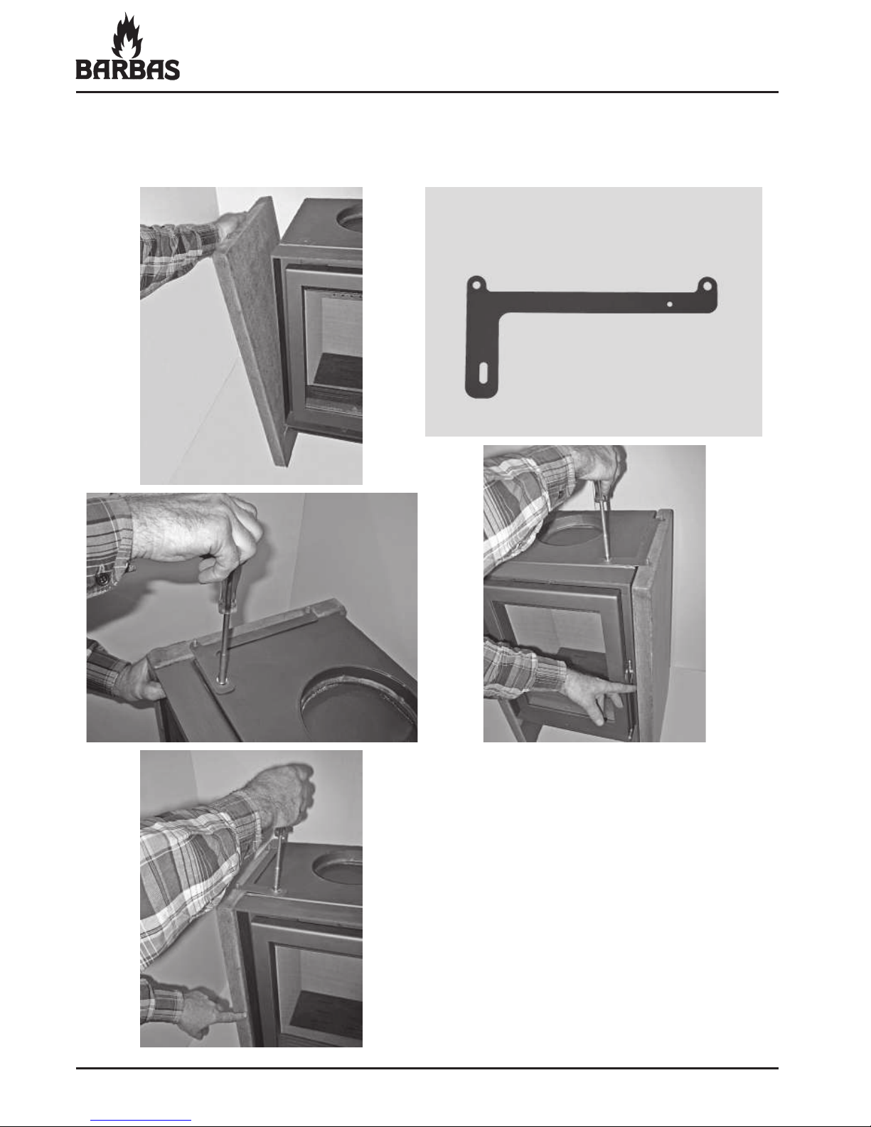
• Place the supplied brass spread anchors (4x) in the top of the soapstone
side panels and screw the threaded pins into them.
Page 26
26
ECO 40 / 52 / 55
• Place the side panels carefully in the two metal cams of the “foot”.
Secure the top with the supplied brackets. Check that the panels are
completely parallel with the appliance.
Page 27

27
ECO 40 / 52 / 55
• Stand the appliance up.
The top of the appliance must be
level with the top of the soapstone
side panels.
The height of the 4 adjusting screws
can be adjusted with an Allen key.
• Fit the soapstone small front panel.
• Fit the soapstone top plate. • Check whether the top plate is 1 -
2 mm free all round.
Page 28

28
ECO 40 / 52 / 55
• Re-hang the door. The appliance is now ready.
Check whether the smoke outlet top-connection is in line with the chimney
• ue.
Fitting the rosette for the smoke outlet rear-connection
• Screw the adjustable feet (3x) in
the metal rosette and set them to
the correct height.
• Fit the metal rosette.
The top of the rosette must lie at
the same height as the soapstone
top plate.
Page 29

29
ECO 40 / 52 / 55
• The appliance is now ready to use.
Check whether the smoke outlet rear-connection is in line with the chimney
• ue.
3.4.2 Connecting to the chimney
Ceiling connection:
Insert a pipe into the sliding sleeve (niche pipe) to the ceiling as deep as
possible. Position a chimney pipe on the top plate and mark off where the top
pipe should be shortened.
Shorten the top pipe and insert it, once more, as deep as possible into the
sliding sleeve in the ceiling. Position the lower pipe over the sealing washer.
Now pull the top pipe down and over the bottom pipe.
Wall connection:
Determine the length of pipe required and push this as far as possible into the
sliding sleeve before the appliance is placed.
Once the appliance is placed, you can pull the pipe from the sliding sleeve and
slide it over the connection ring on the appliance.
Any seams in the • ue gas outlet (pipes) joints should be
sealed with a heat-resistant kit that remains elastic or
with a glass-! bre cord.
Page 30

30
ECO 40 / 52 / 55
4. OPERATION OF THE STOVE
Figure 1: Operation
1 Handle
2 Ceramic heat-proof glass
3 Locking slider for operating pin of • ue gas • ap
4 Operating pin of • ue gas • ap
5 Smoke (• ue gas) outlet Ø150 mm (top/rear connection possibility)
6 Convection air escape opening (permanent)
7 Internal panels (vermiculite plate) / Inner lining
8 Grate / Primary air-supply
9 Ashtray
10 Wood rack
11 Combustion air-supply slider (One combined operation for adjusting all three
air supplies! Primary, Secondary and Tertiary)
12 Intake openings combustion air and convection air
Page 31
31
ECO 40 / 52 / 55
5. STOKING UP FOR THE FIRST TIME
If you have had your chimney breast modi• ed or newly built, • rst allow your
home to dry properly. Walls which have not been allowed to dry properly are a
magnet for dust such as any smoke particles created when stoking up the • re or
suddenly opening the door. Even scorched dust can easily be retained by damp
walls. Think also of dust on the outside of the appliance or on hot radiators etc.
Check that all packaging, stickers etc. and/or all dust and waste has been
cleaned up after the installation work (to avoid it getting scorched/causing a bad
smell).
Check again that all moving parts are in order and that loose parts such as the
retardant plate (brake plate), • ue gas • ap, interior panels, grate etc. are in the
correct position. They may have moved during installation.
The stove has a heat-proof • nish. It only hardens at high temperatures. When
unpacked, it is therefore not fully hardened. It can easily be damaged at this
time.
Begin stoking up the • re with a low • ame (see section 6). Increase the heat
gradually for approx. 2 Hours until you reach the correct output. Keep it at this
level for another 2 - 3 hours. The • nish will now be properly hardened and can
be touched without damaging. The hardening process creates a nasty, though
harmless, smell/vapour.
Check at the start of the heating season that the • ue/chimney is not blocked, for
example by a bird’s nest.
Adequate ventilation is of the utmost importance.
Page 32

32
ECO 40 / 52 / 55
6. USE
6.1. VENTILATION
Air is a vital component of the combustion process. Ensure that there is a
suf• cient supply of fresh air. For each kilo of wood that you put on the • re (door
closed), 10 - 15 m3 of extra air is needed. That means 50 m
3
per hour! As you
can see, a plentiful supply of air is essential. Fresh air supply opening: minimal
50 cm2 (= Ø80 mm).
6.2. GETTING THE FIRE GOING (Figure 1)
When you start the • re, the chimney is still cold and there is little draught. This
means that the chimney’s capacity to draw in air is limited. That is why the air
supply has to be assisted by opening the locking slider (and/or the door) and air
supply slider. Use dry, • ne wood and some scrunched-up paper or • relighters to
start the • re.
open close
Locking slider for operating pin of " ue gas " ap (inside of door).
Locking slider all the way to the right (closed):
Flue gas " ap operation works normally:
Door open Pin comes forwards Flue gas " ap open
Door closed Pin is pressed in by the door Flue gas " ap closed
Locking slider all the way to the left (open):
Flue gas " ap always remains fully open !!
Page 33
33
ECO 40 / 52 / 55
When setting the • re, move the locking slider all the way to the left. If necessary,
leave the door ajar for 10 minutes. Do not open the door wide, as the window
will remain cold. If the door is shut during this time, smoke will condense on the
glass and form soot. Move the air supply slider all the way to the right “ + ” only
when starting the • re.
Prevent white glow and over-fi ring.
6.3. INSTRUCTIONS WHILE STOKING
After approx. 10 minutes, the • re will be burning • ercely. You can now top it up
with a few larger blocks of wood. Move the locking slide all the way to the right
when the blocks are burning well and close the door.
Using the air supply slider you can now adjust the air supply for further
combustion. Make sure the • re burns quietly.
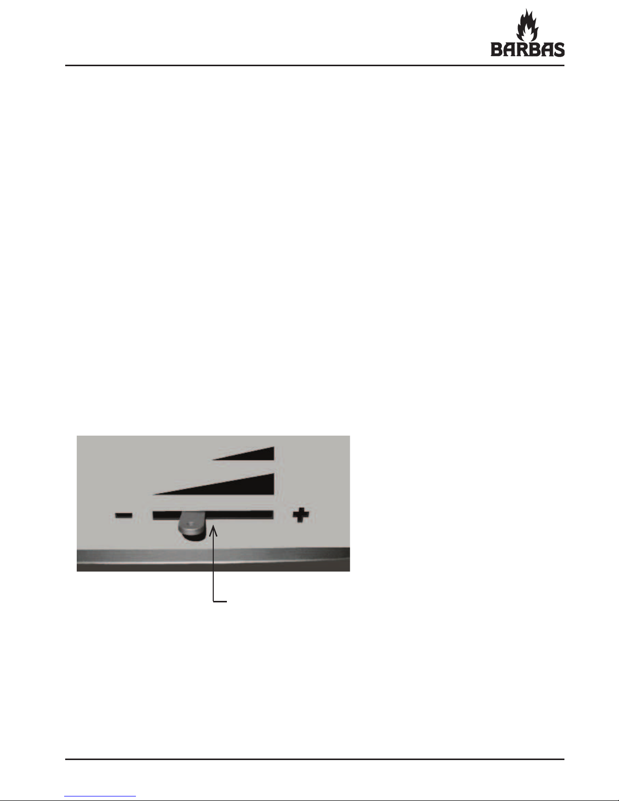
Note: Once you have got the • re going, leave the air supply slider in the centre
position for optimal combustion. Your • re will then be much cleaner and more
ef• cient (more heat, less topping up).
Centre position
Control range of primary air supply (by grate)
Control range of secondary and tertiary air supply
Combustion air supply slider
Page 34
34
ECO 40 / 52 / 55
We recommend that you maintain a substantial layer of ash (2 - 3 cm). This not
only forms a protective layer for the base of the appliance but also signi• cantly
reduces consumption of fuel and allows new wood to catch light easier.
When loading the stove with fuel, two blocks measuring 15 cm long and 30 cm
perimeter (ECO 40), (35 cm perimeter (ECO 52)), (40 cm perimeter (ECO 55))
is suf• cient. Do not add more fuel until the previous fuel has burned down to the
charcoal stage. This is after approximately 45 minutes.
The • ames are then almost no longer visible. Do not leave the door open longer
than necessary.
Weather conditions
In order to reduce pollution and any other inconvenience, we advise not • ring up
the stove when there is no wind, or in foggy/misty conditions.
Smoke development
Your stove has been designed to be used with the load/observation door closed.
Should you use it with the door open, under certain circumstances (presence of
mechanical ventilation, draught, differences in barometric pressure) smoke may
enter the room in which the stove is situated.
Use of the stove
Your stove is suitable for periodic use.
The appliance is • tted with a soapstone or steel casing on the outside.
Soapstone casing: This casing • rst absorb a lot of heat (heat accumulation)
before emitting (radiation / convection) warmth.
Using the stove for short spells is inef• cient.
The stove may only be positioned in a place where the location, construction
and activity in the room can accommodate it without danger.
Ventilation
When using the stove, ensure a good supply of fresh air. After all, the
combustion air is taken from the room where the stove is located. Turn on the
• ue gas fan if the • ue is • tted with one.
Spare parts
Any replacement parts must be new, original parts. Use of non-original/
reconditioned parts will invalidate your warranty.
Page 35
35
ECO 40 / 52 / 55
Continuous stoking with the primary air supply open (combustion air
supply slider is right over to the “ + “ position) (air through the grate)
causes a fi ercely white-hot fi re that can damage the grate and other
parts of the stove.
6.4. HEATING ECONOMICALLY
The most environmentally-friendly and economic way of heating with wood is
to have your • re hot but calm. The ash should appear to glow a soft red-orange
and should not glow like a blacksmith’s • re. Fires like that burn quickly and
intensely, leaving little time for complete combustion.
Your • re is at its most economical when:
• Burning with the door closed. This makes the • re hotter and improves
combustion.
• Using dry and clean wood (as described further in chapter 8).
• Always ensure even combustion. Stoke with the primary air regulator closed.
To do this, place the air supply slider in the centre position.
• The bed of the • re should be composed of one material and the • re must
have easy access to air. Position the blocks of wood (loosely and evenly)
horizontally on the bed of ash, so that they are separate and several
centimetres away from the walls.
6.5. CLEANING THE WINDOW
After several burning hours, a light deposit may form on the inner side of the
window. Once the stove has cooled down, this deposit can be removed using
glass cleaner or ceramic hob cleaner.
Modifi cation
Do not make modi• cations to your stove. Any alteration to your stove, of
whatever nature, will also invalidate your warranty.
Only open the door for • lling and lighting the stove and for removing the ash.
Keep the door shut at all other times.
Page 36
36
ECO 40 / 52 / 55
7. GENERAL HINTS
7.1. TIPS
• Burn dry wood only. Damp wood not only burns poorly, it causes more
pollution in the appliance (window), the chimney, your room (when opening
the door of the appliance, for instance) and the environment. Wood can
only be classi• ed as dry if it has been stored under a Dutch barn for at least
two years (not covered with plastic). Never use painted or impregnated
wood. The gases emitted when burning painted or impregnated wood are
aggressive and will affect the appliance, the environment and your health.
• Ensure that your • re burns well. The smoke generated should be translucent
or white and the windows of the • re will remain clean. We recommend that
you do not ‘pinch off’ your stove (by closing all air openings). Doing so will
hinder combustion which, apart from polluting the atmosphere, will lead to
deposits of soot and tar in your chimney (which, unchecked, will increase the
risk of chimney • re).
• Keep the door shut when the • re is burning. Doing so improves the
performance of your • re 8 - 10 times, bene• ting the environment and the
heat in your home (less topping up, see section 7.2). You will also prevent • re
damage from any particles the • re ‘spits’ out (this is a particular problem with
softwood from conifers). If your • oor contains • ammable material, an extra
• oor plate is required.
• Avoid lighting a • re in misty or still conditions. If the wind is still, there is
hardly any draught in the cold chimney. As smoke is heavier than air, there
is a chance that smoke will enter the room. If there is mist in the air, smoke
coming out of your chimney will cool quickly and fall, causing problems in
your area.
• Do not extinguish your • re with water - let it burn out.
The part of the inner lining that is in direct contact with the • re is clad with
sections of metal and • re-resistant material. Sudden changes in temperature
may lead to it deforming or cracks appearing.
Page 37
37
ECO 40 / 52 / 55
• Chimney • re.
If, despite all the precautions, a • re should occur in the chimney (you
generally notice that because of a roaring sound in the chimney), do the
following:
• Immediately shut the chimney • ap (if • tted).
• Immediately shut the air supply to the stove.
• Call the • re brigade (112).
• Quickly quench the • re in the appliance with sand or soda in order to
prevent smoke in your house.
• Never use water to put out the • re.
• Ventilate.
• If there has been a • re in the chimney, have it swept and inspected for
damage and leakage.
7.2. OUTPUT
In practice, combustion is all about loss. This entails:
• Loss through excess heat leaving the chimney, rather than going into the
room.
• Loss through insuf• cient combustion, such as CO (carbon monoxide) and
soot particles.
• Loss through excessive unburnt fuel in the ash.
The rate at which fuel can burn completely is called the output. A well-stoked
• re achieves output of 75% and thus falls into the category of high-output/
low emissions • res. This means that you bene• t directly by using less wood to
achieve the same level of heat. The environment bene• ts as well: a well-stoked,
high-output appliance means less pollution and fewer odours.
Page 38
38
ECO 40 / 52 / 55
Adverse effects on the output are:
• Burning the • re with the door open.
A warm chimney works in the same way as an extractor. When the door is
open, the chimney draws in much more air than is necessary for combustion.
This relatively cool air cools down the • re.
• Excessive chimney draught.
The combustion air does not reach the fuel, but leaves the appliance via the
chimney. The • re cools and the combustion quality decreases.
• Using too much wood.
This is a problem if your stove is too small. In that case, it becomes
overloaded and burns more wood than heat emitted. In this case too the fuel
cannot burn completely. More to the point, there is not enough air to mix with
the • ames. This has an extra impact on the environment.
• Admitting too much air under the fuel.
(Combustion air supply slider is fully over to the “ + ” position.)
Combustion is raised to high intensity (like a blacksmith’s • re). Combustion
really needs time. If combustion is too intense, there is insuf• cient time for
the stove to radiate all the heat.
The chimney will become excessively hot and the same will be true of the
escaping smoke. This heat is thus lost.
Page 39

39
ECO 40 / 52 / 55
8. FUELS
8.1. WOOD
Suitable fuels are:
• All sorts of clean wood (forested). The wood must have been dried for at
least two years. Well-dried wood has a humidity percentage between 10
and 20%.
Recommended dimensions: • ECO 40: length: ca. 15 cm
outline: ca. 30 cm
• ECO 52: length: ca. 15 cm
outline: ca. 35 cm
• ECO 55: length: ca. 15 cm
outline: ca. 40 cm
• Compressed wood blocks without binder (see wood dimensions).
• Hard woods burn slowly and easily form charcoal; for example hornbeam,
oak, ash, beech, elm and birch.
Softwood burns with more • ame, but forms less charcoal and radiates less
heat. Examples are spruce, pine, poplar and linden.
Unsuitable fuels are:
• Painted, bonded (chipboard, MDF etc.) or impregnated wood, plastic and
other • ammable waste. Stoking a ! re with this is completely forbidden. The
combustion gases released by these materials are aggressive and will attack
your ! replace insert and the environment.
• Paraf! n-containing open ! re lighters are not suitable for a closed ! re. A
closed ! re generates more heat than an open ! re, thus the paraf! n will melt
out of the blocks prematurely.
• Damp wood burns poorly, is unsuitable and produces too much smoke
(including in the room when you are topping up the wood), dirties the glass,
leaves deposits in the chimney and delivers about half the heat output of
dried wood.
The appliance is not suitable for coal ! ring.
ê
ê
ê
Page 40
40
ECO 40 / 52 / 55
9. AMOUNT OF FUEL
9.1. AMOUNT OF FUEL
The stove is constructed for a certain maximum amount of fuel. Remember that
the more fuel you put into your stove, the hotter it will become and overheating
may even occur. If this happens, there is a risk of • re. It may also damage your
appliance and chimney. BARBAS will not assume liability for damage caused by
overheating.
Burning one layer of wood can lead to varying outputs. When used correctly, one
load will burn in around 45 minutes. Putting in too much wood at once can lead
to the appliance being overloaded.
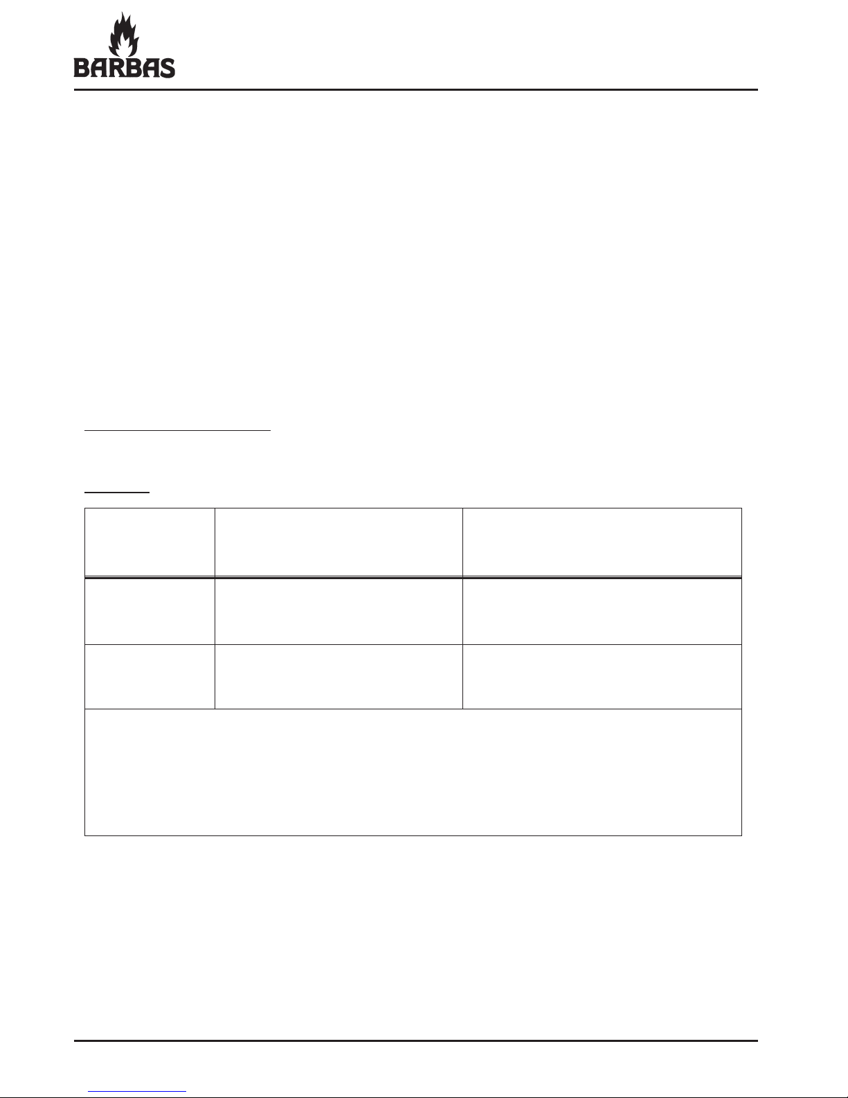
Maximum burning load:
ECO 40:
Per • lling: Calculated per hour:
(= for 45 minutes)
Wood: 2 blocks, 3 blocks,
each around 0.5 kg each around 0.5 kg
Briquettes: 3 briquettes, 5 briquettes,
each around 0.25 kg each around 0.25 kg
Dimensions wood block: c. 15 cm long and 30 cm perimeter
(• 0.5 kg).
The maximum burning load is based on a
nominal
capacity of
5 kW and a
ef• ciency of
78%.
ê
Page 41

41
ECO 40 / 52 / 55
ECO 52:
Per • lling: Calculated per hour:
(= for 45 minutes)
Wood: 2 blocks, each around 0.75 kg 3 blocks, each around 0.75 kg
Briquettes:
3 briquettes, each around 0.35 kg 5 briquettes, each around 0.35 kg
Dimensions wood block: c. 15 cm long and 35 cm perimeter (• 0.75 kg).
The maximum burning load is based on a
nominal
capacity of
7 kW and a
ef• ciency of
75%.
ê
9.2. HEAT RADIATION
The table below shows the temperatures which can theoretically be achieved by
burning wood.
Heat radiation
Sort of fuel kWh/kg
Dry wood (average) 4.3
The heating value of wood (18.7 MJ/kg at 0% humidity) is not affected by the
sort of wood. What does make a difference is the relative humidity of the wood
(15.6 MJ/kg at 15% humidity).
ECO 55:
Per • lling: Calculated per hour:
(= for 45 minutes)
Wood: 2 blocks, each around 1.0 kg 3 blocks, each around 1.0 kg
Briquettes:
3 briquettes, each around 0.5 kg 5 briquettes, each around 0.5 kg
Dimensions wood block: c. 15 cm long and 40 cm perimeter (• 1.0 kg).
The maximum burning load is based on a
maximal
capacity of
± 11 kW and a
ef• ciency of
76%.
ê
Page 42

42
ECO 40 / 52 / 55
10. REGULAR MAINTENANCE
• Emptying the ashtray : Weekly, 48 hours after last heating
• Cleaning the glass : As required
• Door and ashtray seals : Check annually before heating is
resumed. Replace as necessary
• Sweep and inspect chimney : Annually before heating is resumed
• Internal panels : Check annually
* Clean internal panels, as necessary
with hand brush
* Replace panels as necessary
• Grate : Check annually for cracks / breakage
• Sliders / • aps : Check function annually
• Convection channels : Clean annually
• Paint : Annually, if necessary touch up with
BARBAS heat-resistant paint (do not
use with open • res !)
• Parts : Individual parts for replacement/
accessories are available from
your BARBAS dealer
Use only original parts
• Modi• cations : Introduced modi• cations to the
appliance are not permitted
Page 43
43
ECO 40 / 52 / 55
When ordering, please give the serial number.
11. REPLACEMENT PARTS
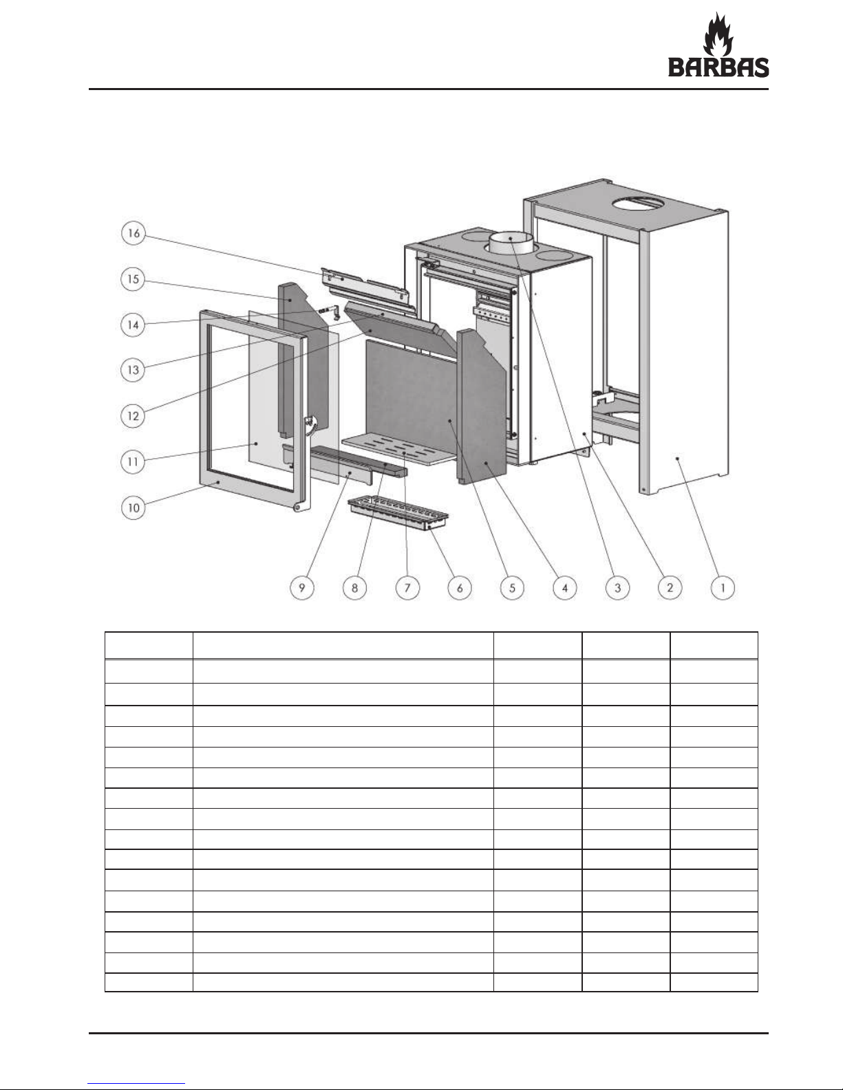
11.1 ECO 40 / 52 / 55 Steel
Item no Description ECO 40 ECO 52 ECO 55
1 STEEL mantle 1 1 1
2 body appliance 1 1 1
3 smoke connection (top or rear) 1 / 1 1 / 1 1 / 1
4 internal panel side R (vermiculite plate) 1 1 1
5 internal panel rear (vermiculite plate) 1 1 1
6 ashtray 1 1 1
7 grate 1 1 1
8 bottom plate front (vermiculite plate) 1 1 1
9 wood rack 1 1 1
10 door 1 1 1
11 glass 1 1 1
12 brake plate (vermiculite plate) 1 1 1
13 brake plate holder 1 1 1
14 operating pin of ! ue gas ! ap 1 1 1
15 internal panel side L (vermiculite plate) 1 1 1
16 ! ue gas ! ap 1 1 1
Page 44
44
ECO 40 / 52 / 55
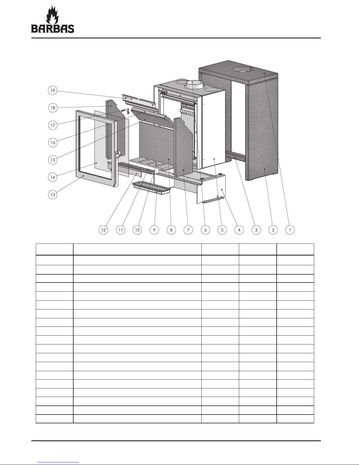
11.2 ECO 40 / 52 / 55 Soapstone
When ordering, please give the serial number.
Item no Description ECO 40 ECO 52 ECO 55
1 SOAPSTONE top plate 1 1 1
2 SOAPSTONE side panel 2 2 2
3 SOAPSTONE small front panel 1 1 1
4 “ foot ” 1 1 1
5 body appliance 1 1 1
6 smoke connection (top or rear) 1 / 1 1 / 1 1 / 1
7 internal panel side R (vermiculite plate) 1 1 1
8 internal panel rear (vermiculite plate) 1 1 1
9 ashtray 1 1 1
10 grate 1 1 1
11 bottom plate front (vermiculite plate) 1 1 1
12 wood rack 1 1 1
13 door 1 1 1
14 glass 1 1 1
15 brake plate (vermiculite plate) 1 1 1
16 brake plate holder 1 1 1
17 operating pin of ! ue gas ! ap 1 1 1
18 internal panel side L (vermiculite plate) 1 1 1
19 ! ue gas ! ap 1 1 1
Page 45

45
ECO 40 / 52 / 55
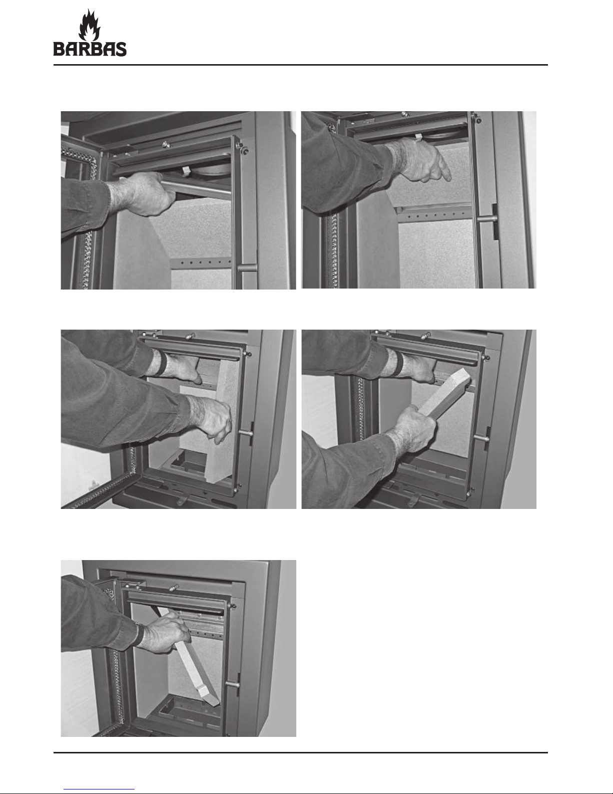
Sequence for replacing the interior of the appliance:
- Remove the grate and ashtray.
- Remove the wood rack. - Remove the bottomplate in the front.
- Remove the • ue gas • ap by lifting it slightly, tipping it backwards and
removing it.
Page 46
46
ECO 40 / 52 / 55
- Remove the brake plate holder
(metal strip, front of brake plate).
- Remove the right-hand side panel. To do this, lift the brake plate slightly.
- Temporarily place the brake plate
one notch higher in the appliance.
- Remove the brake plate by lifting it slightly and removing it sloping to one
side.
Page 47

47
ECO 40 / 52 / 55
- Remove the left-hand side panel.
The entire interior is now disassembled.
The interior is reassembled in the reverse order.
- Remove the rear panel.
Page 48
48
ECO 40 / 52 / 55
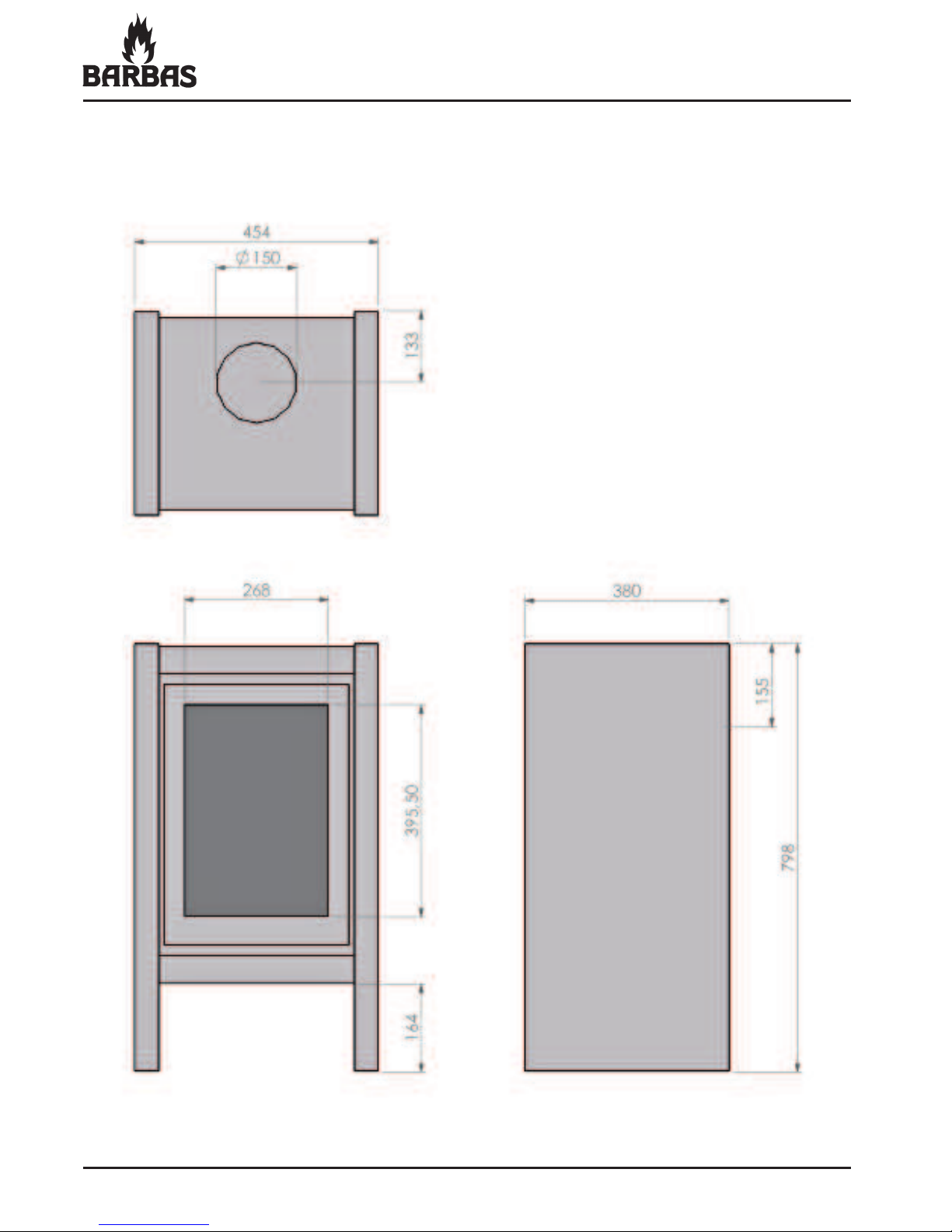
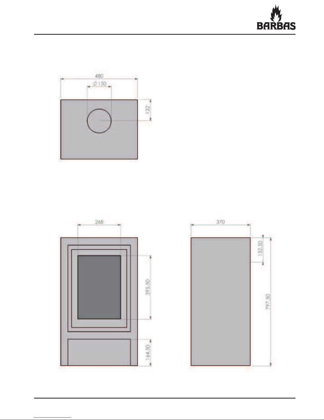
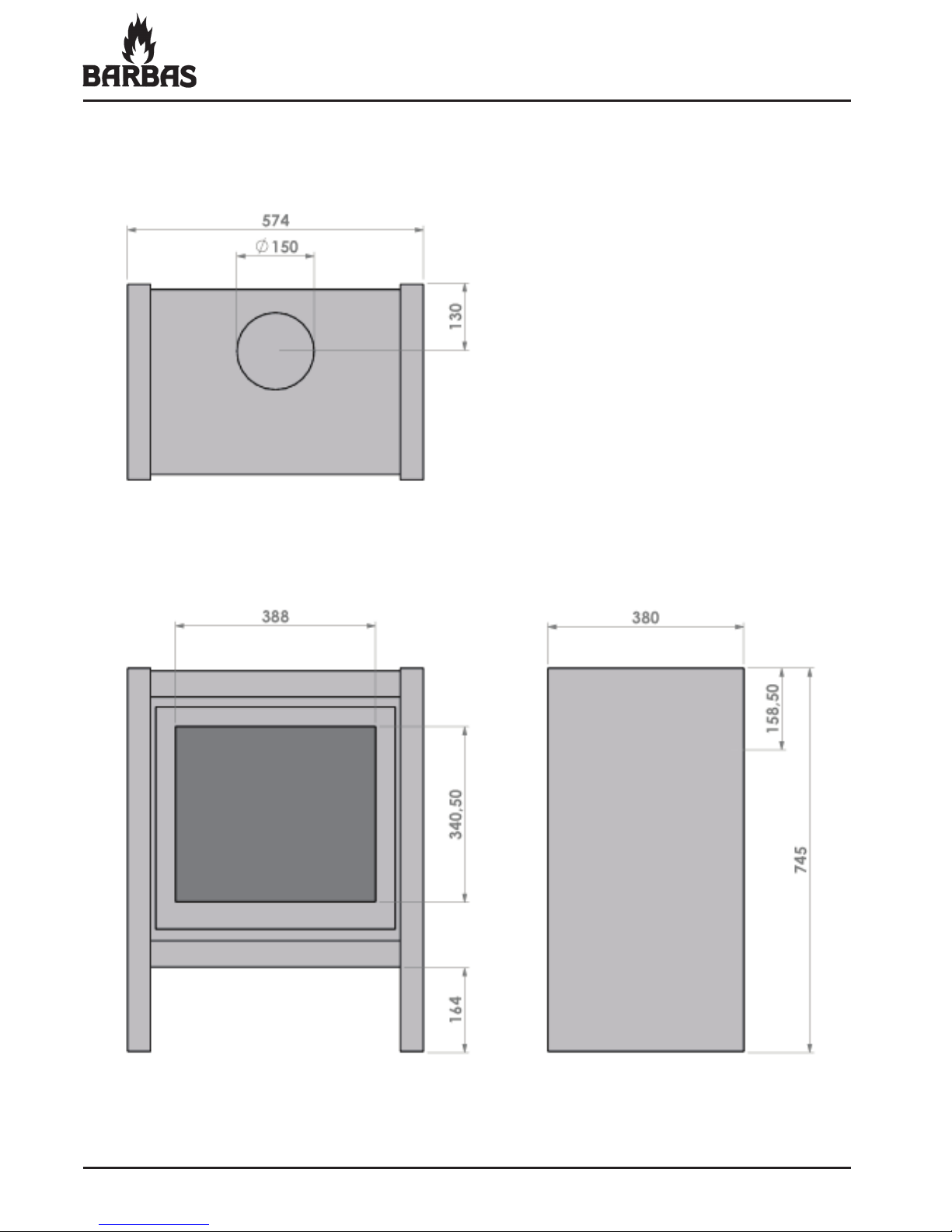
12. DIMENSIONS
12.1 ECO 40 STEEL
Page 49
49
ECO 40 / 52 / 55
12.2 ECO 40 SOAPSTONE
Page 50
50
ECO 40 / 52 / 55
12.3 ECO 52 STEEL
Page 51

51
ECO 40 / 52 / 55
12.4 ECO 52 SOAPSTONE
Page 52

52
ECO 40 / 52 / 55
12.5 ECO 55 STEEL
Page 53

53
ECO 40 / 52 / 55
12.6 ECO 55 SOAPSTONE
Page 54

54
ECO 40 / 52 / 55
13. TECHNICAL DATA
ECO 40
ECO 52
ECO 55
Combustion:
Measured in compliance with EN 13240 : 2001 and EN 13240 - A2 : 2004
Fuel Wood Wood Wood
Output; min. - max. 2 - 7 kW 3 - 9 kW 5 - 11 kW
Nominal output 5 kW 7 kW 8 kW
Ef• ciency 78% 78% 76%
PM10 Dust emissions 14 mg/m
3
n
36 mg/m
3
n
32 mg/m
3
n
Flue gas mass • ow 4.4 g/s 5.1 g/s 9.3 g/s
Flue temperature 298°C 268°C 308°C
Chimney draught 0.12 mbar 0.12 mbar 0.12 mbar
Flue gas connection Ø150 mm Ø150 mm Ø150 mm
(top- and rear
connection)
(Ø148 mm (Ø148 mm (Ø148 mm
ext.) ext.) ext.)
Weight
soapstone-type 162 kg 170 kg 213 kg
steel-type 92 kg 102 kg 125 kg
Inside:
Dimensions
- surface area (w x d)
0.28 x 0.21 = 0.40 x 0.21 = 0.42 x 0.21 =
0.06 m
2
0.08 m
2
0.09 m
2
- clear • re opening (h x w) 340 x 278 mm 285 x 398 mm 450 x 418 mm
Internal panels Vermiculite insulation plates 700 kg/m3, 1100°C
Bottom Vermiculite insulation plates 700 kg/m3, 1100°C
Inner lining Steel (heat-resistant and rust-proof)
Retardant plate (brake plate) Vermiculite insulation plates 700 kg/m3, 1100°C
Flue gas • ap (operated by door) Stainless-steel
Grate Steel
Outside:
Construction Sheet-steel casing
Doors Flat door opening to left
Shutter with • xed handle
Outer • nish Soapstone or steel
Page 55

55
ECO 40 / 52 / 55
ECO 40
ECO 52
ECO 55
Operation: • Handle for opening the door
• Combustion air supply slider
Single combined slide for controlling the
primary, secondary and tertiary air supply
Ash collection: Ashtray with grate
Combustion air supply: Minimum 50 cm2 opening in the room where
the ! re is placed (= Ø80 mm)
Option Floor plate ECO 40
Floor plate ECO 52 / 55
Page 56

56
ECO 40 / 52 / 55
14. FREQUENTLY ASKED QUESTIONS
How often should I have my chimney swept?
At least once a year. If you use your stove more than three times a week on
average, have your chimney swept more often. Have the chimney swept by a
recognised company. Your • re insurance policy may make this a condition and
ask for proof.
What is the difference between net capacity, gross capacity and effi ciency?
Net capacity (= Nominal output) represents the net amount of heat that the
appliance generates.
The total heat content of the fuel is the so called gross capacity.
Ef• ciency is the percentage of fuel converted into useful heat. It is the ratio of
net capacity and gross capacity.
How can I keep the glass clean?
By making a point of using dry, clean wood in the stove. Wood that is too damp
immediately gives off lots of ash.
Make sure the seals are in good working order. Any air seeping out around the
glass part of the door will cool the air, resulting in the • re not burning cleanly.
Can a wood-burning stove/fi replace insert be connected to a central
heating installation?
The Barbas range does not have any stoves/• res that can be connected to
central heating installations. We do not advise attempting it!!
How do I know if I’m heating correctly?
Follow the instructions in this manual.
The " ames should play softly across the wood and the wood should burn evenly.
Once the • re has been burning for a short time, the smoke from the chimney
should be almost translucent.
Page 57
57
ECO 40 / 52 / 55
What is wrong with a smoking chimney?
A seriously smoking chimney means that combustion is less than optimum.
There may be a number of reasons for this. If the • re has only just caught on,
or has recently been topped up, some smoke is normal. By opening the door
for a short period, the wood will catch • re quicker and the smoky period will be
shorter.
If you leave the stove door open, and especially if you burn damp wood, the
result will be a lot of smoke. In both cases, the combustion temperature is too
low. This leaves numerous dangerous compounds intact, which means more
deposits in your chimney and more waste into the environment.
What is the infl uence of soapstone outer fi nish on the stove?
Soapstone functions as a heat buffer.
Its combination of chalky composition and sedimentary structure means that
soapstone heats up more quickly than other sorts of stone and emits heat more
gradually than other stone.
Soapstone equalise the irregularity that is a characteristic of burning wood (heat
radiated is initially double; later half the average).
However, this means that a soapstone stove has a longer warm-up period.
However, it will continue to give off heat for longer.
The soapstones are not like the ones in the brochure. Is this right?
Soapstone is a type of stone that is found in mountain walls (it is sawn out).
Depending on the place in the mountain, the structure may vary. It may be more
or less porous, its structure may be wild or calm. This means that the colour and
• nish may also vary. Stone quarried in the past will thus look different to stone
quarried today.
What should I do if the wood does not catch fi re?
This probably means that the wood is damp. Remove the wood and replace it
with dry wood. If necessary, make a • re with wood briquettes. They are always
dry (they have a moisture content of <10%).
Page 58
58
ECO 40 / 52 / 55
The wood burns up too quickly. What should I do?
Ensure that air cannot get in underneath the fuel. Move the combustion air
supply slider towards the “ - ” position. (The primary air supply is now closed.)
Under these conditions, the layer of ash should no longer burn bright orange/
white but red.
If there is a draught (due to strong wind), air intended as secondary air for above
the fuel may enter through the openings above the door and ! ow straight down
beneath the wood. Also slide the combustion air supply slider tighter shut.
There may be too much of a draught in your chimney, particularly if it is very high
(in excess of 8 m). Ask your supplier to " t a check valve or damper. This may not
be possible in all cases.
Can I leave my stove unattended?
Only do this when the appliance is burning quietly, with just a little wood, with
a closed door and with the combustion air supply slider in the centre position
between “ + ” and “ - ”. In this position, the primary air supply beneath the grate
is closed and the secondary/tertiary air supply is open. Secondary air is supplied
through the small holes in the rear panel of the combustion chamber. Tertiary air
is supplied through the opening behind the glass at the top of the combustion
chamber.
Do not leave children unattended while the stove is burning.
Do I have to take any extra measures if the room I am heating has an
extractor fan (mechanical ventilation)?
A ! ue gas fan is required for permanent extraction of the area in which the
stove is placed.
The type of ! ue gas fan depends on the capacity of the extractor system.
Always consult your installation engineer about this.
What is creosote?
Creosote is a tar-like deposit which is left in the chimney. It is formed in poor
combustion conditions when burning wood (damp wood, pinching off the air
supply to the stove or burning impregnated or painted wood for example).
Creosote ignites at approx. 500°C. This temperature can easily be reached if the
" re is raging. This means that deposits of creosote in your chimney could cause
a chimney " re.
Page 59
59
ECO 40 / 52 / 55
What happens when wood is burnt?
The combustion process.
The combustion of wood involves the following steps.
Drying
The • rst step is that the fuel (wood) dries out. Even at low temperatures
(~ 100°C), any moisture still in the wood will evaporate. This drying procedure
implies a signi• cant loss of energy if wood which is ‘too’ damp is burnt. The
right degree of moisture is achieved after 1.5 - 2 years of drying. The moisture
content is then 15 - 17%.
Decomposition
At moderate - high temperatures (150°C - 350°C), the decomposition process
can be discerned. This is when the chemical structure of the fuel breaks down.
This process involves the creation of volatile compounds such as carbon
monoxide (CO), water vapour (H2O) and methane (CH4). In addition, substances
which are volatile at decomposition temperature but condense at lower
temperatures are often released. These are the tar-like components (this byproduct is also known as creosote, which is deposited in the chimney and cold
parts of the stove in poor burning conditions).
Combustion of the products of decomposition
The volatile compounds burn in the gas phase if O2 (air) is added. The ignition
temperature of these volatile compounds is approx. 550°C.
Combustion of solid hydrocarbons
The solid component that remains consists of pure hydrocarbons, which will burn
at approx. 800°C if O2 (air) is added.
Page 60
02 - 010310 - 327332
INTERFOCOS B.V.
HALLENSTRAAT 17
5531 AB BLADEL
NEDERLAND
E-mail: [email protected]
Internet: www.barbas.com
 Loading...