

Barazza PITAAN2DZI, PITA903DZI, PITA903CZI, PITAAN3CZI, PITAAN722DZI Installation And Use Manual
...
PITA902DZI
PITA903CZI
PITA903DZI
PITA1203CZI
PITA1203DZI
PITAAN2DZI
PITAAN3CZI
PITAAN722DZI
PATA902DZI
PATA903CZI
PATA903DZI
PATA1203CZI
PATA1203DZI
PATAAN2DZI
PATAAN3CZI
taste of design
Kochfelder Tao
Tao hobs
Installations-und Benutzerhandbuch
Installation and use manual

2
Vielen Dank, dass Sie sich für ein Gerät von Barazza
entschieden haben!
Sie haben nun ein Gerät von ausgezeichneter Qualität, das Sie für lange Zeit zuverlässig und sicher bei
Ihrer Arbeit begleiten wird, und Ihnen einen hohen
Leistungsstandard bietet.
Die Installation und der Gebrauch des Geräts sind
einfach und schnell.
Wir möchten Sie bitten, dieses Handbuch aufmerksam
zu lesen: So sichern Sie eine korrekte Installation und
Verwendung, damit Ihr Gerät jahrelang immer perfekt
und wirkungsvoll arbeitet.
Um das Lesen des Handbuchs zu erleichtern, werden
die nachfolgenden Symbole verwendet:
Wichtige Vorschriften zur Sicherheit von
Personen und Gerät
Allgemeine Informationen
Congratulations on purchasing a Barazza appliance!
This safe and reliable high-quality appliance can assist
you in your work with long-lasting top-level performance.
It also has the added advantage of being quick and
simple to install and easy to use.
Please read this manual carefully, as it provides important information for the correct installation and use of
the appliance which will ensure its long-term efficiency.
The following symbols are used to assist you in reading
this manual:
Important rules for personal safety and the
safety of the appliance
General information
Der Hersteller behält sich das Recht vor, ohne eine
Vorankündigungspicht Änderungen an seinen Produkten und
an diesem Handbuch vorzunehmen, die er für angebracht hält.
Die in diesem Handbuch vorhandenen Zeichnungen, Installationspläne und Tabellen dienen nur als Richtschnur und allgemeine
Information.
Die Anschlüsse des Gebäudes müssen den geltenden nationalen
Normen entsprechen.
Das Kopieren, die teilweise oder vollständige Wiedergabe des Inhalts dieses Handbuchs, sowie die Weitergabe dieses Handbuchs
an Dritte ohne Erlaubnis des Herstellers sind verboten.
Dieses Gerät entspricht den Vorschriften der EG-Richtlinie 87/308/
EWG vom 2.6.87 (umgesetzt mit it. Ministerialerlass vom 13.4.89)
über die Verhinderung und Beseitigung von Funkstörungen, Nr.
89/336 zur elektromagnetische Verträglichkeit und 73/23 zur
Niederspannung.
Die Anweisungen dieses Handbuchs gelten ausschließlich für das
jeweilige Aufstellungsland.
The manufacturer reserves the right to make any changes
deemed suitable to the product without prior notice.
The drawings, installation diagrams and tables contained in this
manual are approximate and for informational purposes only.
The systems for connecting the appliance must comply with current
national regulations.
The partial or complete reproduction or photocopying of the contents
of this manual is forbidden, as well as the sending of this manual to
third parties, without the Manufacturer’s permission.
This appliance conforms to the EEC community guidelines 87/308
of 2.6.87 (acknowledged with Ministerial Decree of 13.4.89) on the
prevention and elimination of radio interference, no. 89/336 on
electromagnetic compatibility, 73/23 on low voltage.
The instructions in this booklet are valid only for the country of
destination.
3
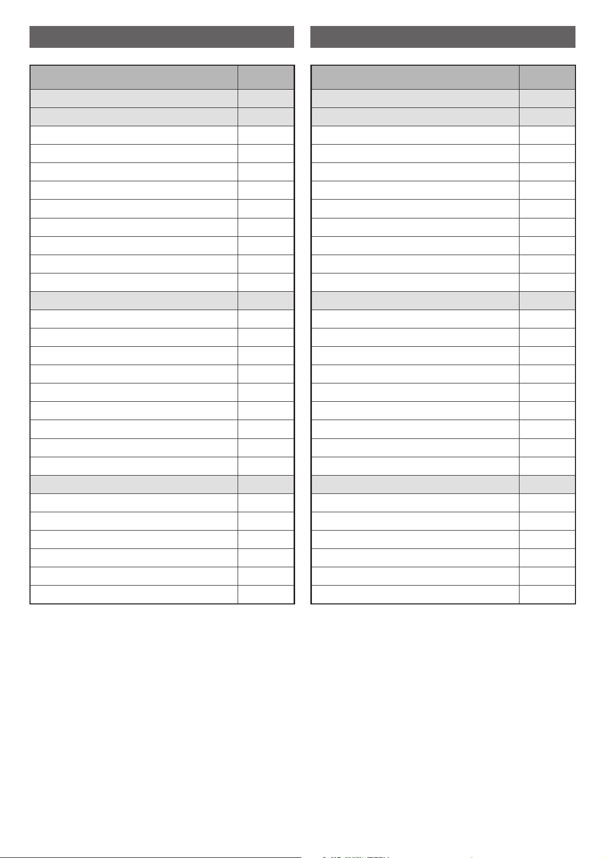
INHALT INDEX
BESCHREIBUNG SEITE
TECHNISCHE DATEN 4
INSTALLATION 6
Sicherheitshinweise 6
Kontrolle und Handhabung 7
Entsorgung der Verpackung 7
Wahl des Installationsortes 8
Elektroanschluss 9
Gasanschluss 11
Einstellung der Minimalleistung 13
Anpassung an andere Gasarten 14
Einbau des Geräts 15
GEBRAUCH 18
Sicherheitshinweise 18
Bevor Sie anfangen 20
Kennen lernen des Geräts 20
Bedienfeld 21
Gut zu wissen 21
Gebrauch des Geräts 22
Gebrauch der Brenner 22
Betriebsstörungen 25
Zubehör 25
WARTUNG 26
Sicherheitshinweise 26
Regelmäßige Wartung 27
Reinigung 27
Zeitweiser Nichtgebrauch 28
Entsorgung nach Außerbetriebnahme 29
Kundendienst 29
DESCRIPTION PAGE
TECHNICAL DATA 4
INSTALLATION 6
Safety warnings 6
Checks and handling 7
Disposal of the packaging 7
Installation site choice 8
Connection to the power mains 9
Gas connection 11
Regulating the minimum 13
Gas conversion 14
Built-in unit installation 15
USAGE 18
Safety warnings 18
Before starting 20
Understanding the appliance 20
Control panel 21
Useful information 21
Using the appliance 22
Using the burners 22
Abnormal operation 25
Accessories 25
MAINTENANCE 26
Safety warnings 26
Maintenance schedule 27
Cleaning 27
Periods of inactivity 28
End-of-life disposal 29
After-sales service 29
4
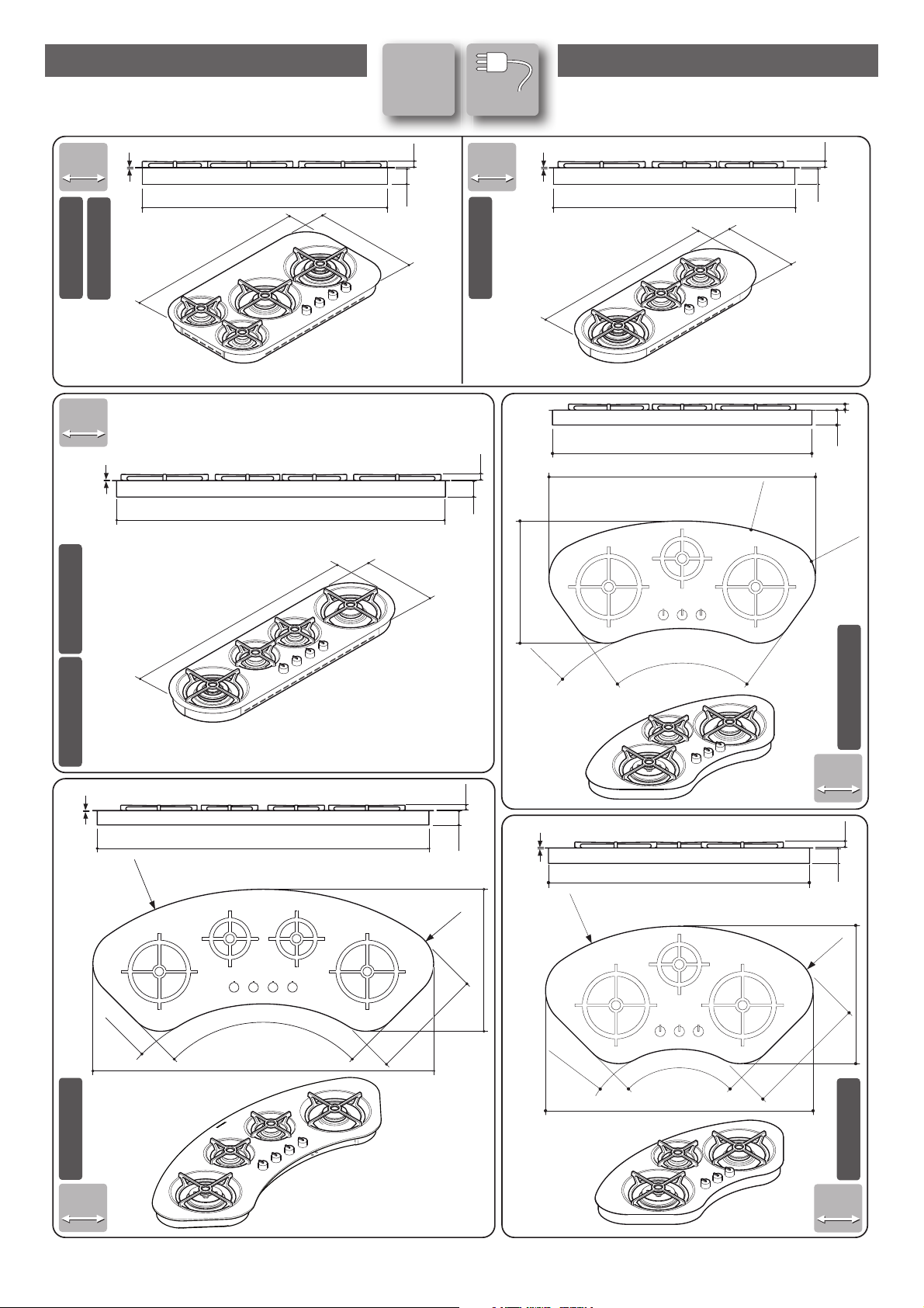
TECHNISCHE DATEN TECHNICAL DATA
Insulating
class
1
1
L=90cm
510
880
R=135
[mm] [mm]
90
90
90
90
PITA903CZI
PITA903DZI
PITA902DZI
[mm]
PITA1203CZI PITA1203DZI
120
120
PITAAN722DZI
R=180
36
0
1160
R=180
360
860
831
56
21
831
1131
956
56
21
56
21
56
21
1
1
[mm]
[mm]
PITAAN2DZI
1
1
C
C
C
C
C
C
R=360
R=810
R=135
450
90°
979,9
503
56
21
1
1303
90°
R 1125
R
135
R 675
45
0
1341,2
558,3
PITAAN3DZI
56
21
72°
966
R 135
R 1020
R 6
20
992,5
455
Die Abmessungen der Sonderausführungen können abweichen.
With custom made models, dimensions
vary.
5
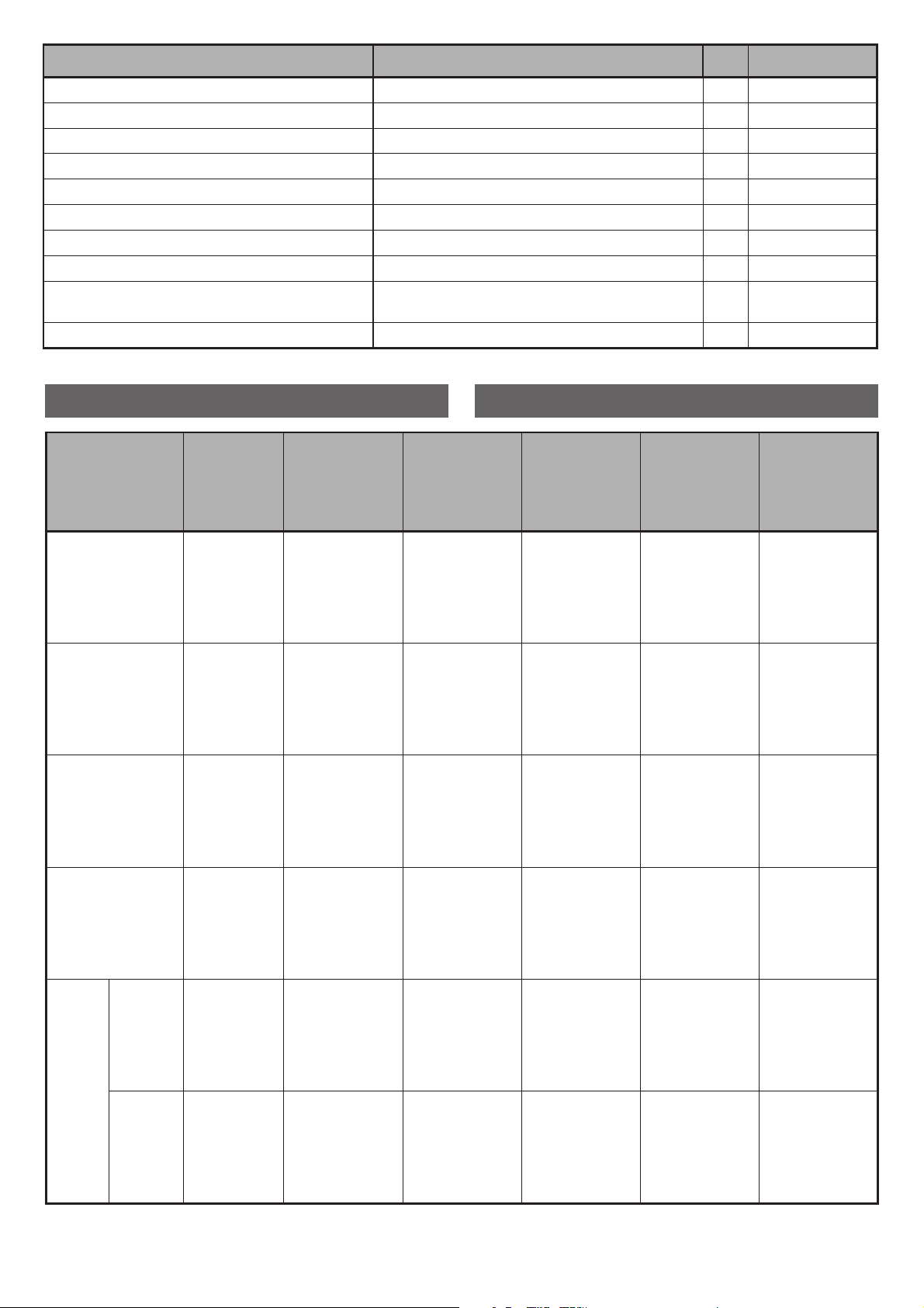
Technische Daten Technical data
Spannung Voltage V 220-230
Frequenz Frequency Hz 50
Leistung der Brenner Burner power
Sparbrenner auxiliary kW 1
Normalbrenner semi-rapid kW 1,75
Starkbrenner rapid kW 3
Dreikranzbrenner triple ring kW 3,3
Dual dual kW 4,2
Kabelart Cable type
H05V2V2-F
3x1 mm
2
Kabellänge Cable length cm 90
TABELLE DÜSEN NOZZLE TABLE
Brenner
Burner
Gasart
Gas type
Betriebs-
druck
Applied
pressure
Leistung
Capacity
ø Düsen
1/100 mm
ø Nozzles
1/100 mm
Nennlei-
stung
Nominal
capacity
Reduzierte
Leistung
Reduced
capacity
Sparbrenner
Auxiliary
G30
G31
G30
G31
G20
G25
30 mbar
37 mbar
50 mbar
50 mbar
20 mbar
25 mbar
g/h 73
g/h 73
g/h 73
g/h 73
l/h 94
l/h 110
50
50
43
43
71
72
kW 1
kW 1
kW 1
kW 1
kW 1
kW 1
kW 0.45
kW 0.45
kW 0.45
kW 0.45
kW 0.45
kW 0.45
Normalbrenner
Semi-rapid
G30
G31
G30
G31
G20
G25
30 mbar
37 mbar
50 mbar
50 mbar
20 mbar
25 mbar
g/h 127
g/h 127
g/h 127
g/h 127
l/h 158
l/h 165
65
65
58
58
96
94
kW 1.75
kW 1.75
kW 1.75
kW 1.75
kW 1.75
kW 1.75
kW 0.45
kW 0.45
kW 0.45
kW 0.45
kW 0.45
kW 0.45
Starkbrenner
Rapid
G30
G31
G30
G31
G20
G25
30 mbar
37 mbar
50 mbar
50 mbar
20 mbar
25 mbar
g/h 218
g/h 218
g/h 218
g/h 218
l/h 270
l/h 292
85
85
75
75
115
121
kW 3
kW 3
kW 3
kW 3
kW 3
kW 3
kW 0.85
kW 0.85
kW 0.85
kW 0.85
kW 0.85
kW 0.85
Dreikranzbrenner
Triple ring
G30
G31
G30
G31
G20
G25
30 mbar
37 mbar
50 mbar
50 mbar
20 mbar
25 mbar
g/h 240
g/h 240
g/h 240
g/h 240
l/h 328
l/h 323
93
93
73
73
124
130
kW 3.3
kW 3.3
kW 3.3
kW 3.3
kW 3.3
kW 3.3
kW 1.40
kW 1.40
kW 1.40
kW 1.40
kW 1.40
kW 1.40
DUAL
DUAL
Innen
Internal
G30
G31
G30
G31
G20
G25
30 mbar
37 mbar
50 mbar
50 mbar
20 mbar
25 mbar
g/h 65
g/h 65
g/h 65
g/h 65
l/h 85
l/h 100
46
46
43
43
72
69
kW 0.9
kW 0.9
kW 0.9
kW 0.9
kW 0.9
kW 0.9
kW 0.3
kW 0.3
kW 0.3
kW 0.3
kW 0.3
kW 0.3
Gesamt
Total
G30
G31
G30
G31
G20
G25
30 mbar
37 mbar
50 mbar
50 mbar
20 mbar
25 mbar
g/h 306
g/h 306
g/h 306
g/h 306
l/h 400
l/h 460
66
66
61
61
102
105
kW 4.2
kW 4.2
kW 4.2
kW 4.2
kW 4.2
kW 4.2
kW 1.75
kW 1.75
kW 1.75
kW 1.75
kW 1.75
kW 1.75
6
SAFETY WARNINGS
Read this instruction booklet carefully before installation and/or use of the appliance and keep it handy
so that all the users can consult it; if you give away or sell
the appliance, please ensure that you give this booklet
to the new user so that he can be informed about its
installation, use and safety rules.
The installation and any interventions on the appliance (special maintenance, nozzle replacement, idle
mode setting, etc.) must be carried out by authorised
personnel only, as specified in this booklet.
The connection systems (gas and electric) and installation rooms must be suitable and satisfy the safety standards in force in the country of use (protective isolating
switch, earthing system, equipotential system, etc.).
The manufacturer will not be held liable if the above
requirements are not satisfied.
During installation, maintenance or repair work,
always switch off the main electrical switch, remove the
connection plug from the socket and shut off the gas
supply taps.
The appliance is not designed for outdoor use.
Appliances may have sharp edges; handle them
with caution and use personal safety equipment (protective shoes, safety gloves, etc.).
INSTALLATION INSTALLATION
SICHERHEITSHINWEISE
Dieses Handbuch mit Anweisungen vor der Instal-
lation und/oder dem Gebrauch des Geräts aufmerksam lesen und an einem Ort aufbewahren, der
für alle Nutzer für weiteres Nachschlagen zugänglich
ist. Bei Abtretung oder Verkauf des Geräts sicherstellen, dass der neue Nutzer auch dieses Handbuch
erhält, damit er über die Installation, den Gebrauch
und die Sicherheitsvorschriften informiert wird.
Die Installation und Eingriffe am Gerät
(außerordentliche Wartung, Austausch der Düsen,
Einstellung der Minimalleistung usw.) dürfen nur
von Fachpersonal nach den Ausführungen in diesem
Handbuch vorgenommen werden.
Die Anschlusseinrichtungen (Gas und Strom) und die
Räume für die Installation müssen dazu geeignet sein
und den geltenden Sicherheitsvorschriften im Verwendungsland entsprechen (Sicherheits- und Trennschalter, geerdete Anlage, Potentialausgleich, usw.).
Der Hersteller übernimmt keine Haftung, wenn oben
stehende Ausführungen nicht eingehalten werden.
Während der Installations-, Wartungs- oder
Reparaturarbeiten immer den Hauptschalter ausschalten, den Netzstecker abziehen und die Hähne für die
Gaszufuhr schließen.
Der Apparat ist nicht für die Nutzung im Freien
ausgelegt.
Die Apparate könnten besonders scharfe
Kanten aufweisen, sie müssen daher mit Vorsicht
und der angemessenen persönlichen Schutzvorrichtung gehandhabt werden (Unfallverhütungsschuhe,
Handschuhe, etc.).
7
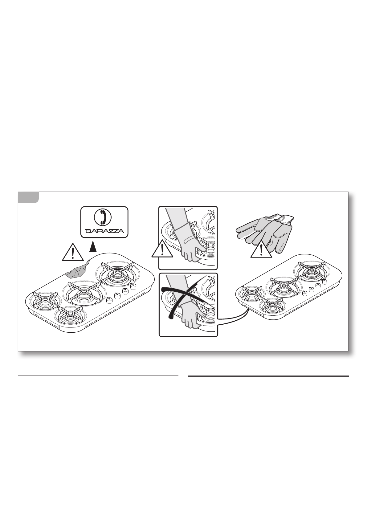
CHECKS AND HANDLING
After having unpacked the appliance and removed all
the packing materials and protective films from the surfaces, check for any anomalies: if you find an anomaly,
do not proceed with the installation but contact your
retailer within 8 days, reporting the data provided on
the appliance’s data plate and describing the problems
you found
(figure 1).
Attention! Do not leave the packing materials (plastic bags, polystyrene, etc.) unattended, as they are a
potential hazard for children and animals (danger
of suffocation).
Move the appliance to the installation location using
appropriate personal safety equipment
(figure 1) and
adopting all the precautions necessary to prevent damage to the appliance, people, animals and property.
DISPOSAL OF THE PACKAGING
Attention! Dispose of the packaging in compliance
with current regulations in the country where the
appliance is installed.
Package composition:
- cardboard
- polyethylene / polypropylene: outer packaging film,
instructions bag
- expanded polystyrene: impact protections.
KONTROLLE UND HANDHABUNG
Nach dem Auspacken des Geräts alle Verpackungsmaterialien und die Schutzfolien der Oberflächen
entfernen, prüfen, ob sichtbare Unregelmäßigkeiten
vorhanden sind: Ist dies der Fall, die Installation
abbrechen und sich innerhalb von 8 Tagen an den
Händler wenden, unter Angabe der Daten auf dem
Typenschild des Geräts und der aufgetretenen Probleme
(Abb. 1).
Achtung! Das verwendete Verpackungsmaterial
(Tüten, Styropor, usw...) nicht unbeaufsichtigt
lassen, da es eine potentielle Gefahr für Kinder
und Tiere darstellt (Erstickungsgefahr).
Das Gerät mit der entsprechenden persönlichen
Schutzausrüstung (Abb. 1) anheben und zum Installationsort bringen, dabei alle notwendigen Sicherheitsmaßnahmen beachten, um Schäden am Gerät,
an Personen, Tieren und Sachen auszuschließen.
OK!
1
ENTSORGUNG DER VERPACKUNG
Achtung! Die Verpackung nach den geltenden
Vorschriften im Aufstellungsland entsorgen.
Zusammensetzung Verpackung:
- Karton
- Polyethylen/ Polypropylen: äußere Schutzhülle
Verpackung, Beutel mit den Anweisungen
- Styropor: Stoßschutz.
8
WAHL DES INSTALLATIONSORTES
Eigenschaften des Installationsraumes
Die Geräte müssen in Innenräumen aufgestellt werden, die
für den Zweck geeignet sind und in denen Temperaturen von
max. 25°C sowie eine Feuchtigkeit von max. 60% herrschen;
sie müssen zudem den Sicherheitsvorschriften im Verwendungsland entsprechen (Sicherheits- und Trennschalter,
geerdete Anlage, Potentialausgleich, usw.). Die Geräte sind
nicht für die Aufstellung im Freien geeignet, dürfen keinen
Witterungseinflüssen ausgesetzt werden. Die Geräte können
auf Möbel montiert werden, die aus hitzebeständigen Materialien gefertigt sind. Ein in die Arbeitsfläche eingebautes
flächenbündiges Kochfeld, geeignet nur für Naturstein (Granit,
Marmor), Massivholz und Fliesen.
Für Arbeitsoberflächen mit anderen Materialien, kontaktieren Sie den Hersteller, ob das Material für den Einbau eines
flächenbündigen Kochfelds geeignet ist.
In den Aufstellungsräumen muss ein kontinuier-
licher Luftaustausch für den ständigen Zufluss der für die
Verbrennung des Gas benötigte Luft gemäß der geltenden
Vorschriften UNI – CIG 7129 und 7131 gewährleistet werden.
Die Öffnungen mit einem Querschnitt von mindestens 100
cm2 müssen so konstruiert sein, dass sie weder von noch von
außen verstopft werden können und sie müssen sich nah
am Boden befinden (
Abb. 2). Jede andere Belüftungsform
muss unbedingt den Anforderungen der Norm UNI – CIG
7129 entsprechen.
Dampfablass
Die Gasgeräte müssen die Verbrennungsprodukte über
Schornsteine, Abzugshauben oder Elektrolüfter (UNI – CIG
7129) (
Abb. 2) mit einer Leistung, die einen stündlichen Luft-
austausch von mindestens 3 mal dem Volumen des Raumes
ermöglicht, direkt ins Freie abführen. Wir erinnern daran, dass
zur Verbrennung 2m
3
/h Luft pro kW Nennwärmebelastung
benötigt werden (siehe Typenschild für die Gesamtwärmebelastung).
Abstand von den Wänden neben und hinter dem Apparat
Die Geräte müssen mit einem gewissen Abstand zur Wand
aufgestellt werden (Abb. 3).
ANMERKUNG:
Immer wenn eine Abzugshaube über dem
Kochfeld angebracht wird, lesen Sie die Montageanleitung
der Abzugshaube, in der der richtige Abstand, der eingehalten
werden muss, aufgeführt wird.
8
AIR
AIR
AIR
2
INSTALLATION SITE CHOICE
Installation site characteristics
The appliances must be placed in suitable interior locations with
a maximum temperature of 25°C and maximum humidity of
60%; the locations must satisfy the safety standards in force in
the country of use (protective isolating switch, earthing system,
equipotential system, etc.). The appliances are not designed
for outdoor use, to be exposed to the elements or bad weather
conditions. Appliances may be assembled onto units made of
heat-resistant materials .
A built-in hob, flush with the worktop, is only suitable with
natural stone (granite, marble), solid wood and tiled bases.
In the instance of bases made from other materials, please ask
the manufacturer whether they are suitable for flush hobs.
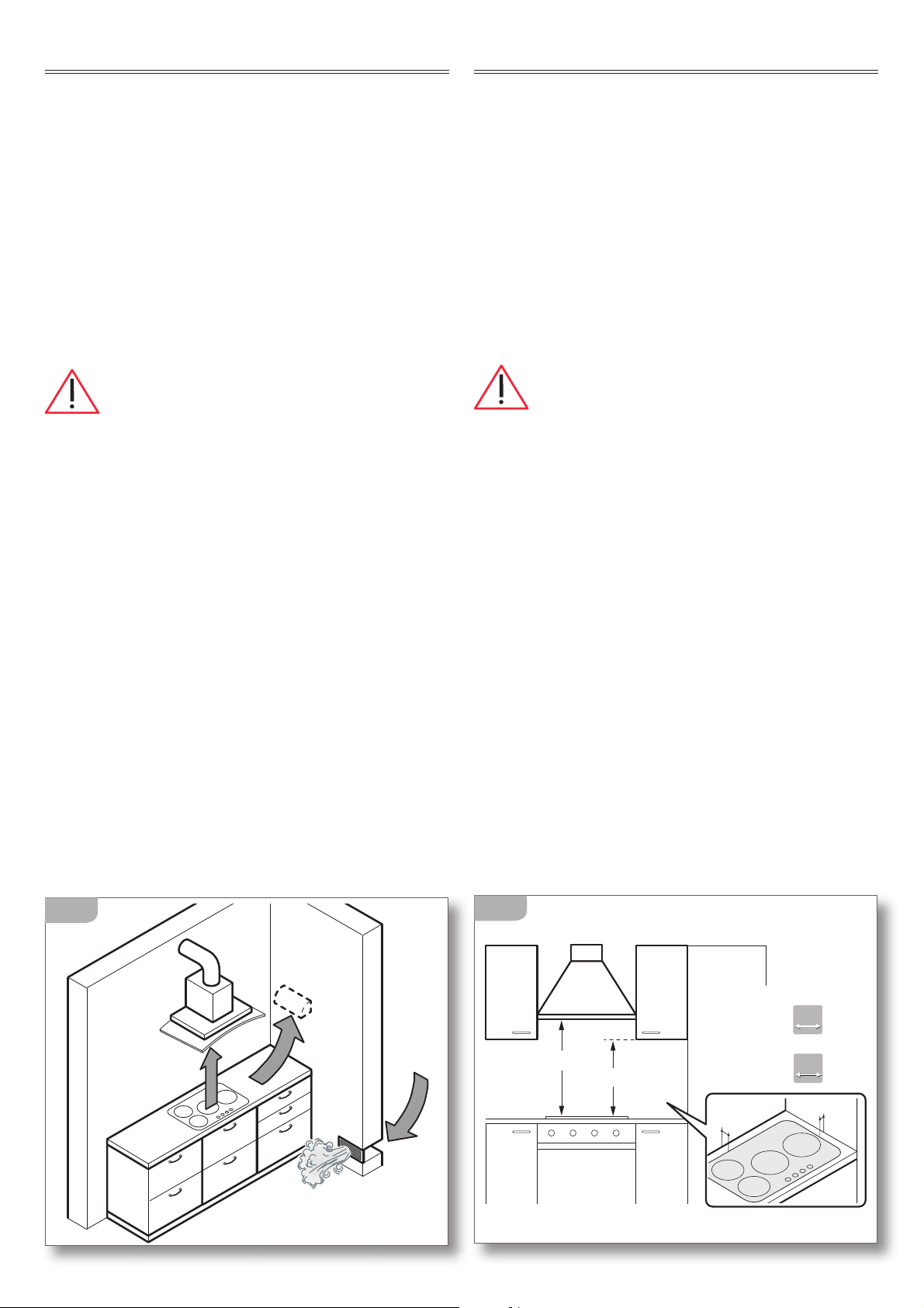
Installation locations must have continuous air
exchange to provide the air flow necessary for gas combustion
as specified in the standards in force UNI – CIG 7129 and 7131.
Openings with an area of at least 100 cm
2
must be constructed
in such a way so that they cannot be obstructed from neither the
inside or the outside and they must be positioned in proximity
to the ground (
figure 2). Every other ventilation type must be in
accordance with specifications in the standard UNI – CIG 7129.
Fume discharge outlet
Gas appliances must release the combustion emissions directly
outside via flues, either by using extractor hoods or electric fans
(UNI – CIG 7129) (
figure 2) with sufficient power to guarantee
hourly air exchange at least 3 times the location volume. It
is to be noted that 2m
3
/h of air is necessary for every kW of
nominal thermal capacity (consult the data plate for total
thermal capacity).
Distance from side and back walls
The appliances must be kept at a specified distance from walls
(
figure 3).
NOTE: If installing a range hood above the hob be sure
to follow the hood assembly instructions and the correct
mounting height contained therein.
min. 65 cm
min. 45 cm
A
B
A= 5 cm
B= 5 cm
A= 4,5 cm
B= 4,5 cm
90
90
120
120
3
9
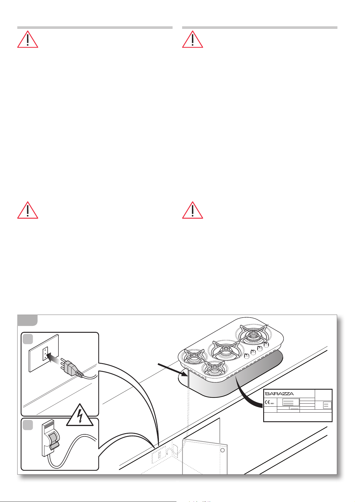
CONNECTION TO THE POWER MAINS
Before making the connection, make certain
that the voltage and frequency indicated on the
data plate match those of the power supply system.
The appliance is supplied with a 90cm-long power cord
(H05V2V2-F) on which a 10 A plug must be installed to
then be connected with a power outlet
(figure 4a).
Alternatively, the cable can be connected directly to
the distribution network
(figure 4b): in this case an om-
nipolar disconnecting switch must be provided, with a
minimum opening of the contacts that allows complete
disconnection in category III overvoltage conditions.
Both the power outlet and omnipolar switch must
be up to standard and located in a position which
is accessible even after the appliance is installed.
If the appliance is installed together with an oven, the
connection of the two appliances must be independ
-
ent for electrical safety reasons.
The power cord must NOT:
- be crushed or rolled up;
- come into contact with any type of liquid, sharp or hot
objects or corrosive substances;
- reach, at any point, a temperature which is 50°C higher
than the room temperature;
- be replaced with a different type of cable (see “Techni-
cal data” on page 4)
or with a cable which is not up to
standard;
- be lengthened with extensions.
ELEKTROANSCHLUSS
Vor dem Anschluss prüfen, dass die auf dem
Typenschild angegebene Spannung und Frequenz
denen der Stromversorgung entsprechen.
Der Apparat wird bereits mit einem 90 cm langen
Stromkabel (H05V2V2-F) geliefert, an das ein Stecker
montiert werden muss, der für 10 A ausgelegt ist, um
diesen dann an eine Steckdose anzuschließen
(Abb. 4a).
Alternativ dazu kann das Kabel direkt an das Verteilernetz angeschlossen werden (Abb. 4b): In diesem
Fall muss ein allpoliger Trennschalter mit einem
Kontaktabstand vorgesehen sein, der die vollständige Abschaltung unter den Bedingungen Kategorie
Überspannung III erlaubt.
Sowohl der Elektrostecker als auch der allpolige
Trennschalter müssen normgerecht ausgeführt sein
und sich in einer Position befinden, die auch bei ein
gebautem Gerät zugänglich ist. Wenn das Gerät zusammen mit einem Backofen installiert wird, müssen
die beiden Geräte aus Sicherheitsgründen getrennt
an die Elektroversorgung angeschlossen werden.
Das Stromkabel darf NICHT:
- gedrückt oder verdreht sein;
- mit Flüssigkeiten jeder Art, scharfen oder heißen
Gegenständen und ätzenden Substanzen in Berührung kommen;
- in keinem Punkt eine Temperatur erreichen, die die
Raumtemperatur um 50°C übersteigt;
- durch ein Kabel anderen Typs ersetzt werden
(„siehe
Technische Daten“ S. 4)
oder durch ein nicht norm-
gerechtes Kabel;
- durch Verlängerungskabel verlängert werden.
H05V2V2-F
3x1mm
2
90 cm
10A
B
A
G30 - 28 mbar
220V-240V 50HZ
0,000 Kw
G20 - 20 mbar
Questo apparecchio deve essere installato conformemente alle norme in
vigore e utilizzato solamente in locale ben areato. Consultare il libretto
istruzioni
p
rima di installare e usare l'aparecchio.
REGOLATO A
GAS
G20
N°: XXXXXXXXX
CATEGORIA II 2H3+ IT
F.lli BARAZZA s.r.l.
MADE IN ITALY
Qn
g/h
00.0 kW
000 g/h
XXXXX
XXXXX
XXXXX
MOD
ART
N°
istruzioni prima di installare e usare laparecchio
.
4
10
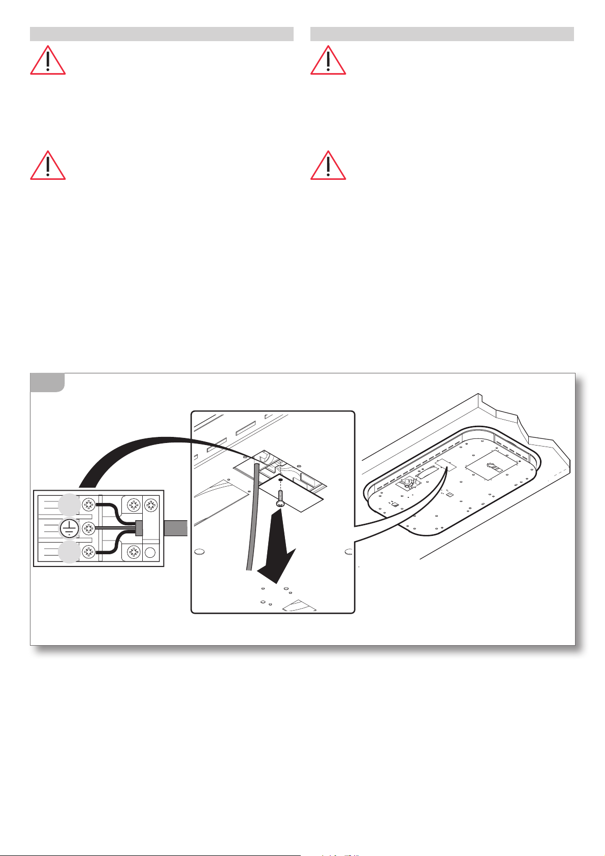
AUSTAUSCH DES STROMKABELS
Im Bedarfsfall kann das Stromkabel mit ei-
nem anderen mit denselben Eigenschaften
(siehe
“Technische Daten” S. 4)
und in Übereinstimmung
mit den geltenden Vorschriften im Installationsland ausgetauscht werden.
Wenn das Gerät bereits angeschlossen ist,
trennen Sie es vom Stromnetz und schließen Sie
die Absperrhähne der Gasversorgung.
Um Zugriff auf die elektrischen Anschlüsse zu erhalten, entfernen Sie die Abdeckung des Klemmenbretts
durch Lösen der entsprechenden Schraube
(Abb. 5).
Trennen Sie das alte Kabel von den Klemmen,
entfernen Sie es und schließen Sie das neue Kabel
(ausschließlich vom Typ H05V2V2-F) an die entsprechenden Klemmen an, N - L - Erde.
Sichern Sie das neue Kabel mit dem Kabeldurchgang
und verschließen Sie das Klemmenbrett wieder mit
seiner Abdeckung.
N
L
5
POWER CORD REPLACEMENT
If necessary, the power cord can be replaced
with an identical type
(see “Technical data” on page
4)
in compliance with current regulations in the
country where the appliance is installed.
If the appliance is already connected,
disconnect the electrical power and shut off gas
supply taps.
To access the electrical connections, remove the cover
from the terminal board by unscrewing the screws
(figure 5).
Disconnect the old cord from the terminals and remove
it; connect the new cord (only the H05V2V2-F type) into
the respective terminals N - L - Earth.
Cover the new cord with the appropriate cord holder and
re-close the terminal, replacing its cover.
 Loading...