

BAPI ZPS-ACC07, ZPS-ACC09, ZPS-ACC08, ZPS-ACC05, ZPS-ACC06 Installation And Operation Instructions Manual
...Page 1
Static Pressure Accessories
Installation and Operation Instructions
13044_Ins_ZPS_ACC
Rev. 05/22/2017
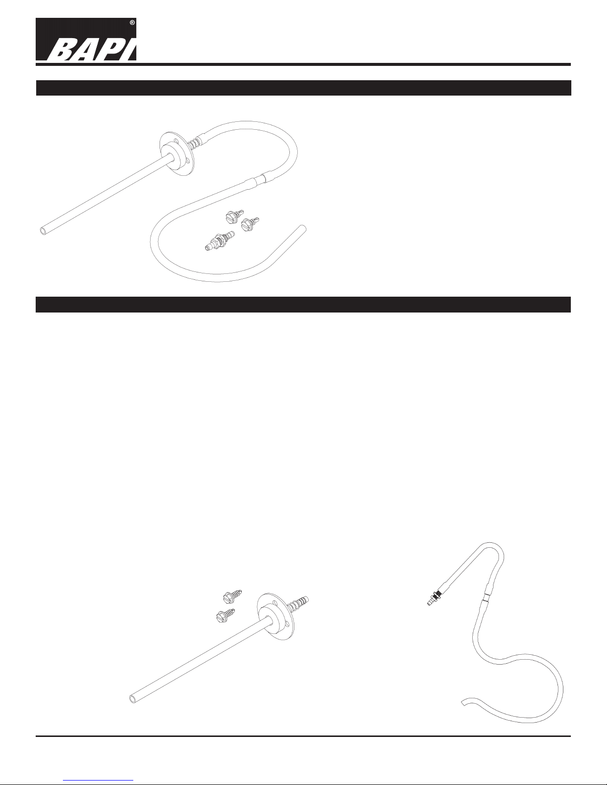
Duct Static Pressure Probe Assembly
The duct static pressure probe assembly consists
of a static pressure probe, a six inch piece of silicon
rubber tubing, a twelve inch piece of silicon rubber
tubing, two self drilling sheet metal screws and a
pressure spike reducer.
Fig. 1: BAPI ZPS-ACC07
Mounting the Duct Static Pressure Probe, Hoses and Damper
Positioning the duct static pressure probe assembly to get the best results requires a little planning. Ideally the probe
should be located 1/2 the distance from the fan to the end of the longest duct run. The probe should be a minimum of ve
duct diameters from any vanes, straighteners, reducers or bends. The probe may be placed within 1/2 duct diameter of a
lter as long as the lter is ve duct diameters from any other restriction.
Drill a 1/4 inch hole in the duct for the probe. Insert the 6 inch long section of the probe into the duct work and rotate so
the air ow arrow is pointing in the same direction as the air ow in the duct. Using the two self drilling screws provided
secure the probe to the duct. For round duct pick the two holes in the probe mounting ange that touch the duct surface.
Position the probe so that it is at a right angle to the duct surface or at right angles to a line tangent to the duct surface for
round duct. Being off by +/- 5 degrees angle is acceptable.
Long runs of tubing will damp out quick pressure uctuations. Where the ZPS unit must be located close to the static
pressure tube BAPI provides a pressure spike reducer. The pressure spike reducer provides a slight restriction in the
tubing. The volume of tubing after the pressure spike reducer determines the time constant, the longer the tubing the
greater the pressure spike reduction.
Place the 6” tube towards the pressure source. Connect the 12” tube to your ZPS pressure transmitter. If you do not get
the dampening that you desire, increase the tubing length from the blue plastic snubber to the pressure sensor.
Condensation running down the interior of the tubing will damage the sensor. Forming a drip loop in the tubing just
before it enters the ZPS transmitter is good practice, see Fig 4. The distance from the bottom of the loop to the ZPS’s
pressure port should be one to two inches (2.5 to 5 cm) greater than the highest air pressure, including error conditions, in
the duct system.
Building Automation Products, Inc., 750 North Royal Avenue, Gays Mills, WI 54631 USA
Tel:+1-608-735-4800 • Fax+1-608-735-4804 • E-mail:sales@bapihvac.com • Web:www.bapihvac.com
Fig. 2:
ZPS-ACC08 Static
Tube
Fig. 3:
ZPS-ACC09
Hoses with
Pressure
Damper
1 of 3
Page 2
Static Pressure Accessories
Installation and Operation Instructions
13044_Ins_ZPS_ACC
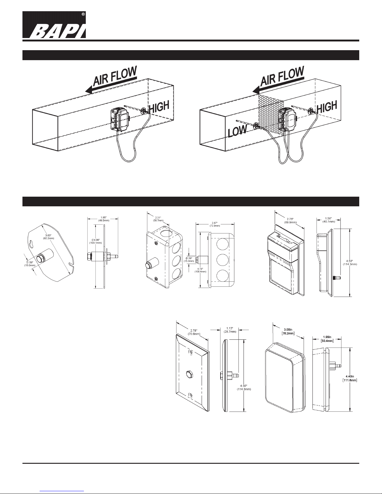
Typical Applications - Duct Static Pressure Probe
Fig. 4:
Measuring duct static pressure with pressure
transmitter and static pressure probe
Fig. 5:
Measuring duct air lter pressure drop with pressure
transmitter and two static pressure probes.
Mounting Wall & Ceiling Pressure Pickup Ports
Rev. 05/22/2017
Fig. 6: Ceiling Mount Cover
(ZPS-ACC05)
Mount the static pressure pickup port in an area
that is representative of the zone near the center
of the zone. Do not mount in a closet or other
enclosed space, or in areas that are prone to
drafts.
It is best to mount the wall pickup port using an
electrical box. A simple hole in the wallboard may
be used, but be sure that the foam gasket on the
back of the pickup seals tightly against the wall.
Attach tubing to the barbed tting on the back of
the pickup port and run the tubing to the pressure
sensor, forming a drip loop in the tubing just before
connecting to the pressure sensor.
The ceiling pickups are sized to t through a
standard 3/4-inch thick acoustic ceiling tile. Cut a
5/8 inch hole in the tile. Place the static pressure
sensor on top of the tile with the lter into the hole.
The lter should stick out slightly below the tile’s room surface. Attach tubing to the barbed tting on the back of pickup
port and run the tubing to the pressure sensor, forming a drip loop in the tubing just before connecting the tubing to the
pressure sensor.
Building Automation Products, Inc., 750 North Royal Avenue, Gays Mills, WI 54631 USA
Tel:+1-608-735-4800 • Fax+1-608-735-4804 • E-mail:sales@bapihvac.com • Web:www.bapihvac.com
Fig. 7: Ceiling Mount Cover &
J-Box (ZPS-ACC06)
Fig. 9: Wall Plate
(ZPS-ACC01)
Fig. 8: Delta Style Enclosure
(ZPS-ACC03)
Fig. 10: BAPI-Stat
“Quantum” (ZPS-ACC04)
2 of 3
Page 3

Static Pressure Accessories
Installation and Operation Instructions
13044_Ins_ZPS_ACC
Typical Applications - Wall & Ceiling Pressure Pickup Ports
Rev. 05/22/2017
Fig. 11: Measuring static pressure differences between two rooms using two BAPI ZPS-ACC01
stainless steel wall plates and a BAPI ZPS Pressure Transmitter.
Fig. 12:
Exploded view drawing of ceiling static pressure pickup
port, BAPI ZPS-ACC05, showing how to mount in
ceiling tile.
Building Automation Products, Inc., 750 North Royal Avenue, Gays Mills, WI 54631 USA
Tel:+1-608-735-4800 • Fax+1-608-735-4804 • E-mail:sales@bapihvac.com • Web:www.bapihvac.com
3 of 3
 Loading...