

Page 1
*
Zone Pressure Sensors (ZPS) - BACK MOUNT
Installation and Operation Instructions
18646_Ins_ZPS_BB_BM
Product Identification
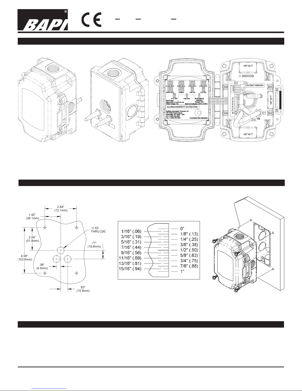
Fig. 1
Non-Display ZPS in a
BAPI-BoxBack Mount
Fig. 2
Rear Vew of ZPS in a
BAPI-Box Back Mount
4/6/07rev.
Fig. 3
Display ZPS in a BAPI-Box
Back Mount, Cover Open
Mounting
Mount the unit to its mounting surface with four #10 screws through the holes in the mounting feet. The preferred mounting orientation is with the pressure ports facing down.
Fig 4 Mounting Hole Pattern
Note: BAPI recommends using #10
screws that require 5/32" pilot holes.
Tools & Material List
Fig. 5 Mounting over a 2x4 Junction Box
Screwdriver #10 Screws Sealant Filled Connectors
Drill with 5/32” bit Wire
Building Automation Products, Inc., 750 North Royal Avenue, Gays Mills, WI 54631 USA
Tel:+1-608-735-4800 • Fax+1-608-735-4804 • E-mail:sales@bapihvac.com • Web:www.bapihvac.com
Specifications subject to change without notice.
1 of 3
Page 2
Zone Pressure Sensors (ZPS) - BACK MOUNT
Installation and Operation Instructions
18646_Ins_ZPS_BB_BM
Output Termination
4/6/07rev.
Desired Output Wire connections
4 to 20 mA Red (V+); Black (Return{4 to 20 mA Signal}); White (Not used)
0 to 5 V or 0 to 10 V Red (V+); Black (Ground); White (Output Voltage)
4 to 20 mA is “two wire” operation, the ZPS’s red wire connects to a positive direct current voltage of 7 to 45 VDC,
the ZPS’s black wire becomes the return of the 4 to 20 mA signal and the ZPS’s white wire, while unused, must be
insulated from accidental contact with ground or any other potential. For 4 to 20 mA signaling only direct current can
be used to power the ZPS.
0 to 5 V or 0 to 10 V is “three wire” operation, the ZPS’s red wire connects to either 7 to 45 VDC or 7 to 32 VAC (0-5
VDC output) or 13 to 45 VDC or 13 to 32 VAC (0-10 VDC output), the ZPS’s black wire is connected to ground and
the ZPS’s white wire is connected to an analog input of the controller. BAPI insulates the white wire in the factory
before shipping to you, please remove the connector and strip the insulation from the white wire as desired.
To ensure that all wires are properly terminated, twist the stripped ends of each circuit together before inserting into
the splice terminals. Gently tug on the wire after terminating to make sure of a good connection. If the wire comes
out of the termination repeat the splice procedure.
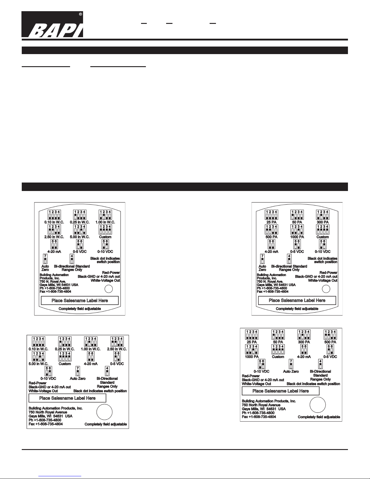
Dip Switch Settings - Inches, Pascals, Display and No Display
Figure 6:
DIP Switch Settings,
ZPS with No Display,
Inches W.C.
Figure 8:
DIP Switch Settings,
ZPS with Display,
Inches W.C.
DIP Switch Settings,
Figure 7:
DIP Switch Settings,
ZPS with No Display ,
Pascals
Figure 9:
ZPS with Display ,
Pascals
Building Automation Products, Inc., 750 North Royal Avenue, Gays Mills, WI 54631 USA
Tel:+1-608-735-4800 • Fax+1-608-735-4804 • E-mail:sales@bapihvac.com • Web:www.bapihvac.com
Specifications subject to change without notice.
2 of 3
Page 3

Zone Pressure Sensors (ZPS) - BACK MOUNT
Installation and Operation Instructions
18646_Ins_ZPS_BB_BM
Pressure Range Select
4/6/07rev.
To adjust the pressure range, set dip switches 1-4 to the desired pressure range using the the label found inside the
cover of the ZPS unit (or shown on this pg 2). Moving the Bi-Directional dip switch (#4) to the up position doubles
the pressure range. For example, the 0 to .25” W.C. range becomes -.25” to .25” W.C. if the Bi-Directional dip
switch is in the up position.
Note: If any of the switches are placed in an undefined combination the LED will fast blink and the output will be forced
to 4mA or zero volts.
Output Range Select
To adjust the output range, set dip switches 5 & 6 to the desired output range using the the label found inside the
cover of the ZPS unit (or shown on pg 2).
Note: If any of the switches are placed in an undefined combination the LED will fast blink and the output will be forced
to 4mA or zero volts.
Auto-Zero Select
To auto zero the BAPI ZPS, remove the tubing
from the pressure ports (to remove the normal
pressure source). Make sure that the pressure ports are sheltered from any drafts,
including the technician’s breath. Ideally the
two ports should be connected together with a
short piece of tubing. Turning on switch 7
starts the auto-zero process. Switches 1 through 6 may be in any allowed
configuration. The LED will blink at a fast rate and the output will be
forced to zero (4mA or 0V) while the auto-zero is being performed. When
Before
auto-zero
Fig. 10 Auto-Zero
During
auto-zero
After
auto-
zero
the LED blinks at a slow rate, turn off switch 7 and reconnect the pressure
source.
Switch 8
Switch 8 is reserved for Factory use, leave in the off position.
Diagnostics
PROBLEMS:
LED does not light
LED is blinking fast
(1/2 second on, 1/2 second off)
Output stuck (high or low)
Output not tracking pressure properly
LED Operation
POSSIBLE SOLUTIONS:
- Check power connections for proper power
- The unit may be performing an auto-zero. Wait 10 seconds and check again.
- The dip switches are in an unsupported configuration, check the dip switch
settings, both pressure and output, and change them to ranges desired
- Remove pressure from ports and perform auto-zero procedure
- Check dip switches for proper pressure range selection
- Check dip switches for proper output range selection
LED off No Power
LED Blinking 1/2 sec on, 1/2 sec off Auto-zero or dip switch in undefined configuration
LED on Normal operation
LED Blinking 1/2 sec on, 4 sec off Auto-zero complete
Building Automation Products, Inc., 750 North Royal Avenue, Gays Mills, WI 54631 USA
Tel:+1-608-735-4800 • Fax+1-608-735-4804 • E-mail:sales@bapihvac.com • Web:www.bapihvac.com
Specifications subject to change without notice.
3 of 3
 Loading...