

Page 1
Water Leak Detector
BA/LDT Accessories
Termination and Troubleshooting
26268_ins_LDT
Overview & Identication
The Water Leak Detector is designed to sense the presence of water and alert a central monitoring system of the
potentially destructive situation. Upon water detection, an alarm relay changes state, and a local red LED illuminates.
The transmitter can be set for latching alarm or non-latching alarm with normally energized or de-energized operation.
An optional remote water sensor is available for small inaccessible locations such as AHU pans or under oor water
detection.
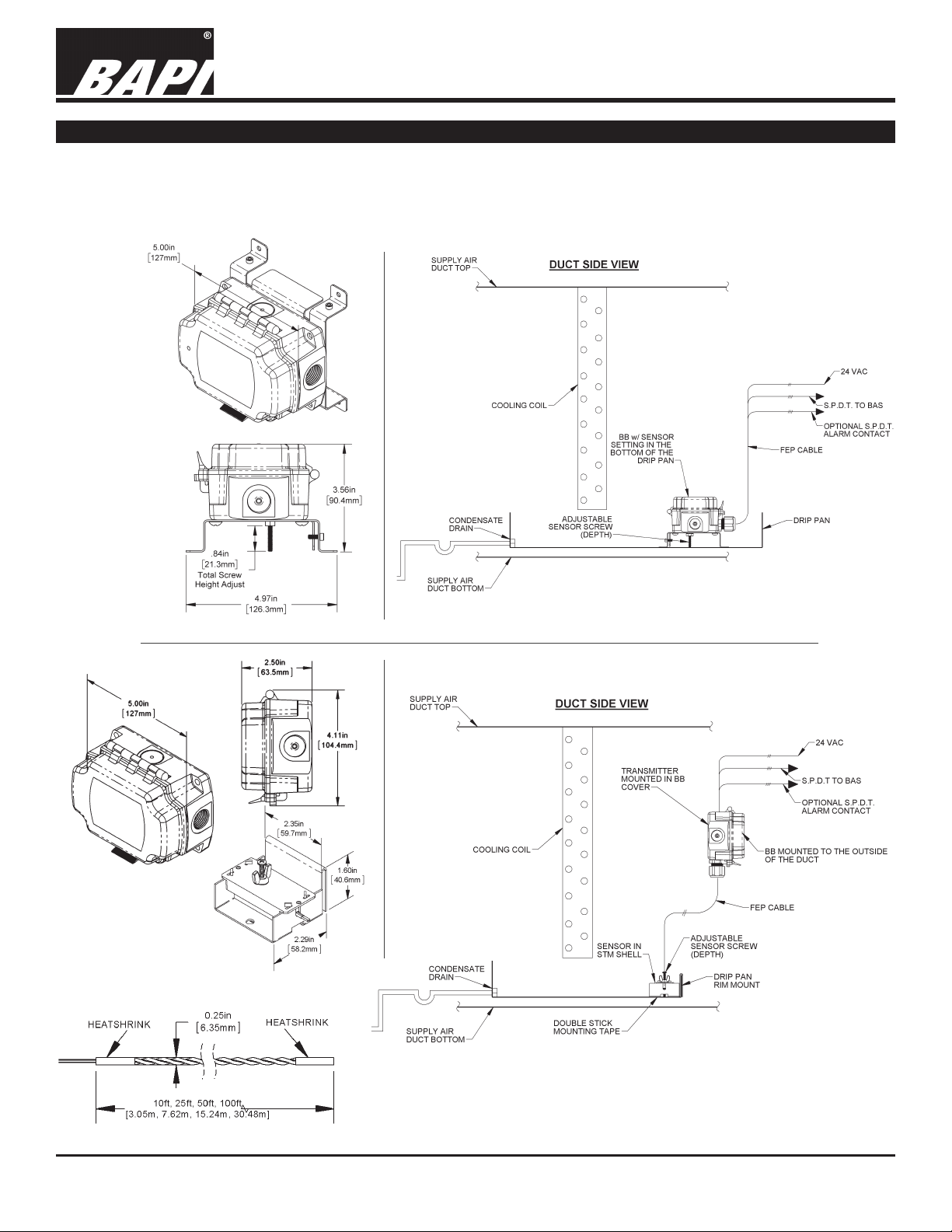
Fig. 1:
Water Leak
Detector
with Internal
Sensor Probe
rev. 11/16/18
Fig. 3:
Water Leak Detector
with Remote Spot
Sensor (right) and Water
Rope Sensor (below)
Fig. 2:
Water Leak Detector with Built In Sensor and a
5 Amp Relay in a System Diagram (Side View)
Fig. 4:
Water Leak Detector with Remote Spot Sensor or
optional Water Rope Sensor (not shown) and a 5 Amp
Relay in a System Diagram (Side View)
Specications subject to change without notice.
1 of 6
Page 2
BA/LDT Accessories
26268_ins_LDT
Mounting
Place the transmitter in a location where a water leak is
likely to cause damage such as a cooling coil pan, a hot
water tank pan, under a sink, under an elevated oor,
or in a drop ceiling under pipes. The transmitter can be
independently mounted in a visible location by using a
remote water sensor and waterproof cable as shown
in Fig. 4. Terminate the transmitter as shown in the
termination section.
1. Set the transmitter where water is most likely to be a
problem or in the collection pan under the water coil or
heater (Fig. 5).
• Alternatively a water sensor or remote water sensor
can be attached to the pan edge with two set screws
(Fig. 6). Do not over tighten or puncture the pan.
• Alternatively a remote water sensor can be attached
to the pan or oor with mounting tape (Fig. 7). Clean
surface thoroughly before setting the sensor in place
and push sensor down rmly. Mount the detector
enclosure in a visible location within cable length of the
remote water sensor.
• Alternatively a remote water sensor can be attached
to the oor with screws (Fig. 8). Mount the detector
enclosure in a more visible location within cable length
of the remote water sensor.
• Alternatively the rope water sensor can be laid on the
oor or under pipes as shown in Figs. 10, 11, 12 & 13.
Cable clamps can be used to secure the sensor to the
oor.
2. Adjust the depth screw on the sensor probe in the middle
of the open enclosure to the alarm depth (Fig. 5). If using
a remote water sensor, adjust the depth screw as shown
in Fig. 9. The rope sensor detects water 1/8” off the oor
and has no adjustment.
3. Run the cable to the transmitter location leaving enough
slack to terminate and allow for some repositioning as
needed. Use a strain relief on the entering cable so the
wires do not tug on the terminals directly.
4. Terminate and congure in accordance with the
termination section.
Water Leak Detector
Termination and Troubleshooting
rev. 11/16/18
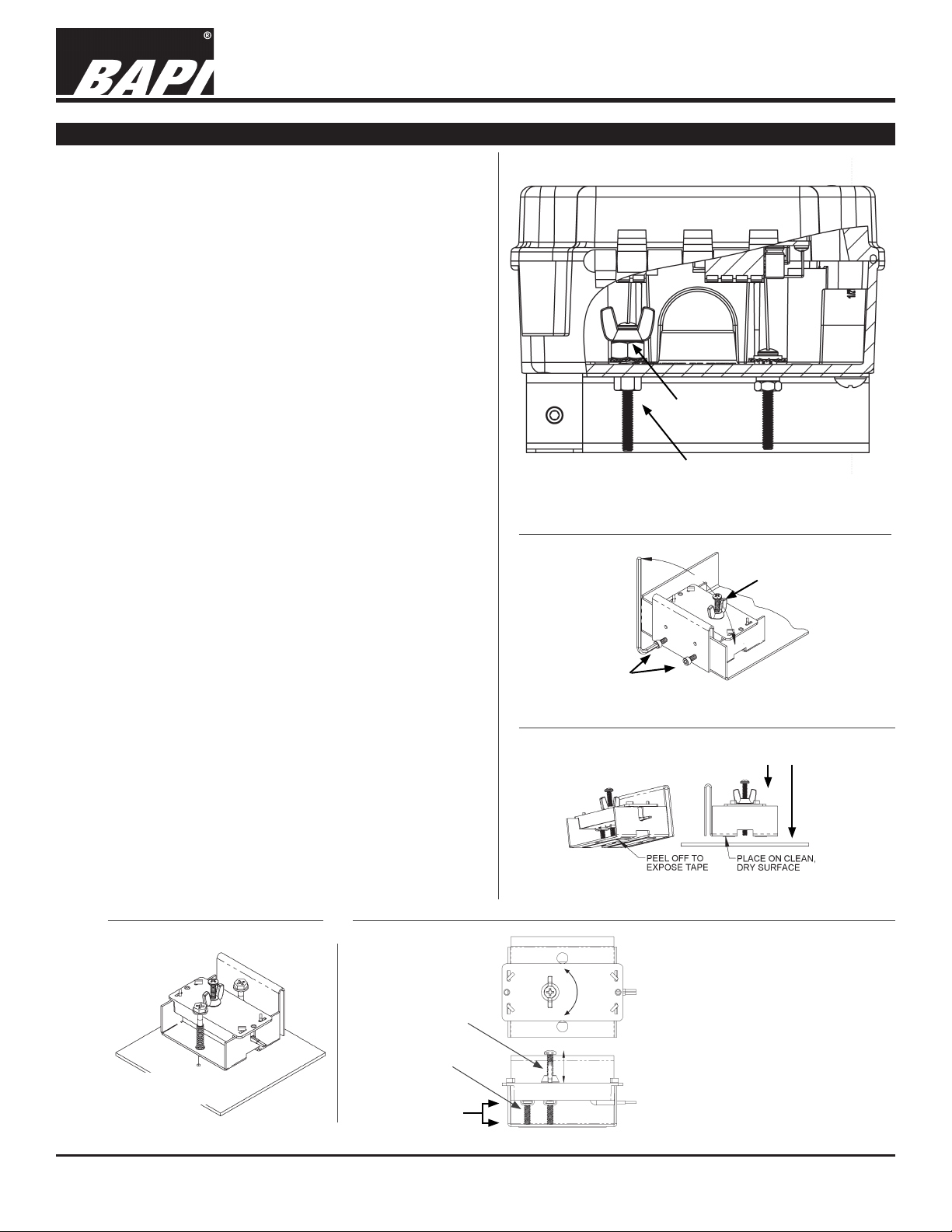
Mounting
Nut
Sensor Probe
Screw
Fig. 5: Leak Detector with Sensor in a BAPI-Box
Detection depth
adjust screw
Pan edge
mounting
screws
Fig. 6: Water Sensor Pan Rim Mounting
Firmly push down
on clean surface
Fig. 7: Remote Water Sensor Tape Mount
Fig. 8: Remote
Water Sensor
Floor Mount
Installer-provided
mounting screws
Fig. 9: Remote
Water Sensor
Up
Depth Adjusting
Detection depth
adjust screw
Reference probe
Detection depth
adjust from 1/16”
to 1/2” depth
Specications subject to change without notice.
Down
1. Loosen wing nut.
2. Set the required depth of the
sensor probe screw using a #2
Phillips screwdriver.
3. Hold the sensor probe screw
stationary with the screwdriver.
4. Turn the wing nut down the probe
screw until it engages the plastic.
5. Tighten the wing nut 1/4 turn into
the plastic.
2 of 6
Page 3

26268_ins_LDT
Mounting continued...
Fig. 10:
Hot Water Tank
Pan Mounting
Water Leak Detector
BA/LDT Accessories
Termination and Troubleshooting
rev. 11/16/18
Fig. 12:
Vertical
Pipe Sensor
Mounting
Fig. 11: Sub-Floor Sensor Mounting
The following combinations of sensors can be used:
1. Two rope sensors with a combined length of no more
than 100’.
2. Two spot sensors with a combined length of no more
than 75’.
3. One spot sensor with a maximum length of 25’ and
one rope sensor of no more than 50’.
Note: Shielded or twisted pair wire cannot be used
to extend the sensor wires. This applies to both the
remote spot sensor as well as the rope sensor.
Fig. 13: Horizontal Pipe Sensor Mounting
Specications subject to change without notice.
3 of 6
Page 4

26268_ins_LDT
Wiring and Termination
Water Leak Detector
BA/LDT Accessories
Termination and Troubleshooting
rev. 11/16/18
Terminal Description
A ..........Water Sensor (No polarity to water
sensor cable)
B ..........Water Sensor (No polarity to water
sensor cable)
NC2* .......Alarm Contact 2, Normally Closed to
C2 when De-energized
C2 .........Alarm Contact 2, Common
NO2 ........Alarm Contact 2, Normally Open to
C2 when De-energized
NC1* .......Alarm Contact 1, Normally Closed to
C1 when De-energized
C1 .........Alarm Contact 1, Common
Fig. 14: Leak Detector Circuit Board
Sensitivity Adjustment for 10’ and 100’ Remote Rope Sensors
The unit’s leak detection sensitivity is set at the
factory. However, for the 10’ and 100’ remote rope
sensors, the sensitivity may need to be adjusted
in the eld.
If you are using a 10’ remote rope and it won’t
respond, rotate the sensitivity adjustment
potentiometer 5 turns counterclockwise.
If you are using a 100’ remote rope and it is too
sensitive, then rotate the sensitivity adjustment
potentiometer 5 turns clockwise.
NO1 ........Alarm Contact 1, Normally Open to
C1 when De-energized
GND/NEU Power supply ground/neutral
V+/HOT ...Power supply input 24VAC +/- 10%
*Not used for low current relay version, SPST,
Form A
Sensitivity Adjustment Potentiometer
Fig. 15: Leak
Detector Circuit
Board
Specications subject to change without notice.
4 of 6
Page 5

Water Leak Detector
BA/LDT Accessories
Termination and Troubleshooting
26268_ins_LDT
Set Up and Commissioning
Indication/Controls Description
Red LED
.........................LED illuminates when water is detected
Green LED .....................LED illuminates when normal power is applied
Reset Button
Latching Relay
Non-Latching Relay
Supervised Relay***
Unsupervised Relay
..................Resets latching alarm contact (only if water is no longer present)
................Left side of J1 set to top two pins listed as “L”
........Left side of J1 set to bottom two pins listed as “N” (Default)
.......Right side of J1 set to top two pins listed as “S” (Default)
.......Right side of J1 set to bottom two pins listed as “U”
*** Supervised means the relay is energized when not in alarm and the relay de-energizes on a power failure or alarm.
1. After the unit is installed and wired, turn on the power. (24VAC +/- 10%)
2. Check that the green LED is “on”. If it is not “on”, check the power source.
3. Dampen a cloth or sponge and touch both the sensor probe tip and the sensor base. An alarm should occur
within 5 seconds.
4. The red LED should illuminate and the relay(s) should de-energize, or energize if set up as unsupervised. (To
check relay status, measure the resistance at the relay contacts or monitor the status from the BAS screen.)
5. Remove the dampened rag or sponge to clear the alarm. If the unit is set up for a non-latching relay (J1 jumper
across the “N” pins), the red LED and relay(s) will energize, or de-energize if set up as a unsupervised relay. If
the unit is set up for a latching relay (J1 jumper across the “L” pins), the operator must push the reset switch on
the detector board or interrupt power to clear the alarm.
6. Check the depth screw (see Mounting Section) to be sure it’s at the appropriate water depth for alarm.
rev. 11/16/18
Operation Sequence
When power is applied, the green LED will illuminate and and the unit will start to detect for water at the sensor
probe. When there is no detection of water (normal condition), the relays are not in an alarm state and the red LED
remains off. For units set up in the “unsupervised” relay mode, the relays are de-energized. For units set up in the
“supervised” relay mode (default), the relays will be energized. (Note: When there is a loss of power, a supervised
relay will drop out indicating a water detection alarm.)
Within 5 seconds of water detection, the relays go into an alarm state and the red LED illuminates. For units set
up in the “unsupervised” relay mode, the relays are energized. For units set up in the “supervised” relay mode
(default), the relays are de-energized.
If the unit is in non-latching or auto-reset (default) operation, then the alarm state will automatically reset when the
water has dried up. If the unit is in latching or manual-reset operation, then the unit will stay in an alarm state until
the reset button is pressed or power is cycled. If there is still water detected during a reset button push, the unit will
not reset. If there is still water detected after a power interrupt, the unit will initiate another alarm within 5 seconds.
Diagnostics
Possible Problem Possible Solution
Green LED Not On 1. Check for proper power to the unit (see power specs on back page).
Red LED Not Working 1. Check for proper power to the unit (see power specs on back page).
Or Relay Not Energizing. 2. Check if water is touching the sensor probe and reference probe.
3. Adjust sensor probe depth.
4. For rope sensor units, check the sensitivity adjustment as described on page 4.
Unit Will Not Reset 1. Check for the presence of water or debris touching the two sensor probes.
2. Be sure the sensor wires are not shorted.
3. If the L pins on J1 are shorted, push the reset button or cycle power.
4. For rope sensor units, check the sensitivity adjustment as described on page 4.
Specications subject to change without notice.
5 of 6
Page 6

Water Leak Detector
BA/LDT Accessories
Termination and Troubleshooting
26268_ins_LDT
Maintenance
Check the water sensor probe once a year to be sure there is no dirt or debris collected around the probes. Dirt or
debris around the probes may cause nuisance alarms in moist situations. Change the service intervals depending
on environmental conditions. In very clean conditions the probe may never need maintenance. Rope sensor may be
wiped down with isopropyl alcohol, warm soapy water on a cotton cloth or placed in a dishwasher.
Cautions/Warnings
This unit is not intended to be a safety device. In no event shall BAPI or its ofcers, directors, employees or agents be
liable to any company or individual for any indirect, incidental, special, exemplary, punitive or consequential damages
including, without limitation, economic or commercial losses, arising out of or resulting from the misuse of this water
detector as a safety device.
Specications
rev. 11/16/18
Power: 24VAC +/- 10%
5 Amp Relays: 4 Watt/ 4 VA max
0.5 Amp Relays: 2 Watt/ 2 VA max
(not intended to switch a load)
Wiring: Flex Connector or Liquid Tight Fitting
Relays Up to 6 wires
Transmitter 2 wires for Power
Mounting: Lays in the pan or attached with a pan edge
hook with screws
Sensor:
Standard Single SS probe from bottom of BB with
adjustable depth screw from .063” to .84”
Optional Remote water sensor with depth screw with
adjustable depth from 1/16” to 1/2”
Optional Remote long line water sensor (Rope)
Detects water over the full length at
depths >0.125”. Note: 100 ft maximum
including non-sensing extension cable.
Detector Transmitter:
Alarm Contacts
LDT2: Two SPST, 0.5A relay outputs, 10W max
LDT3: One SPDT, 5A relay output
LDT4: Two SPDT, 5A relay outputs
SPST or SPDT, 30 VAC/DC max
Selectable as normally Energized or
De-energized
Indication 1 Green Power LED, 1 Red Alarm LED
Reset Action If latching, local push button or power
Sensor Reaction
Termination: Terminal strip, 4-10 terminals, 12-24AWG
Agency: RoHS, UL94V-0, UV-rated in Enclosure
LDT1: One SPST, 0.5A relay output, 10W max
interrupt
Responds to presence of water within 5
seconds
Set Up:
BB Sensor Adjustable depth from .063” to
.84” (≈1/16th” default)
Remote Sensor Adjustment depth from 1/16” to
1/2” (≈1/16th” default)
Latching Latching Version - Stays
Jumper
Non-Latching Version (default) -
Supervision Supervised Version (default) Jumper De-energized when in alarm.
Unsupervised Version -
Enclosure Ratings:
Remote Sensor Submersible, w/FEP plenum-
Rope Sensor Plenum rated
Transmitter BAPI-Box, NEMA 4
Ambient:
Remote Sensor -40 to 185ºF (-40 to 85ºC),
0 to 100%RH, Condensing
Transmitter (BB) -40 to 185ºF (-40 to 85ºC),
0 to 95%RH, Non-condensing
Rope Sensor 32 to 167ºF (0 to 75ºC),
0 to 95%RH, Non-condensing
Enclosure Materials:
Remote Sensor Aluminum bracket w/ABS plastic
Transmitter (BB) Polycarbonate
Note: This unit is not intended to be a
energized after water has dried up
Alarm follows wet or dry surface
Note: Relay will drop out on
loss of power indicating a water
detection alarm.
Energized when in alarm.
rated, waterproof cable
shell
safety device.
Specications subject to change without notice.
6 of 6
 Loading...