

Page 1
VOC Duct and Rough Service Sensor
Overview and Identication
Humans respirate Volatile Organic Compounds
(VOCs) as well as CO2. The BAPI sensor measures
these VOCs and indicates when a space is occupied
just as well as a CO
The advantage of the VOC sensor is that it
measures air contaminants from other sources
besides respiration, such as building materials,
cleaners, perfumes and furniture and carpet
off-gassing.
Using this sensor for Demand Controlled Ventilation
then is a way of achieving true indoor air quality,
rather than just CO
it requires no additional work on your part. That’s
because the sensor converts the VOC reading to a
equivalent level. This lets you use ASHRAE’s
CO
2
-based VRP schedule to ventilate.
CO
2
The Duct Sensor samples duct air using an aspiration
tube, while the Rough Service unit features a
ventilated BAPI-Box and is ideal for areas such as
outdoor air plenums, equipment rooms, green houses
and warehouses. The VOC level is indicated as
“Good, Fair or Poor” by three discrete green, yellow
and red LED’s on the front of the unit.
reaches 2,000 PPM, the red LED will begin to ash
because it has hit its maximum output.
sensor.
2
dilution. A further benet is that
2
If the output
Installation & Operating Instructions
rev. 06/05/1840699_ins_VOC_3LED_BB
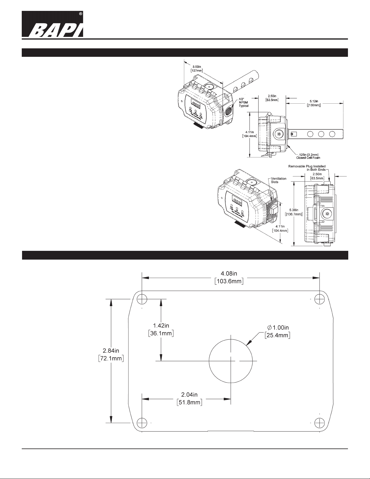
Fig. 1: Duct
VOC Sensor
Fig. 2: Rough
Service VOC
Sensor
Mounting Template
Fig. 3: Mounting
Template, Actual Size
Specications subject to change without notice.
1 of 6
Page 2
VOC Duct and Rough Service Sensor
Installation & Operating Instructions
rev. 06/05/1840699_ins_VOC_3LED_BB
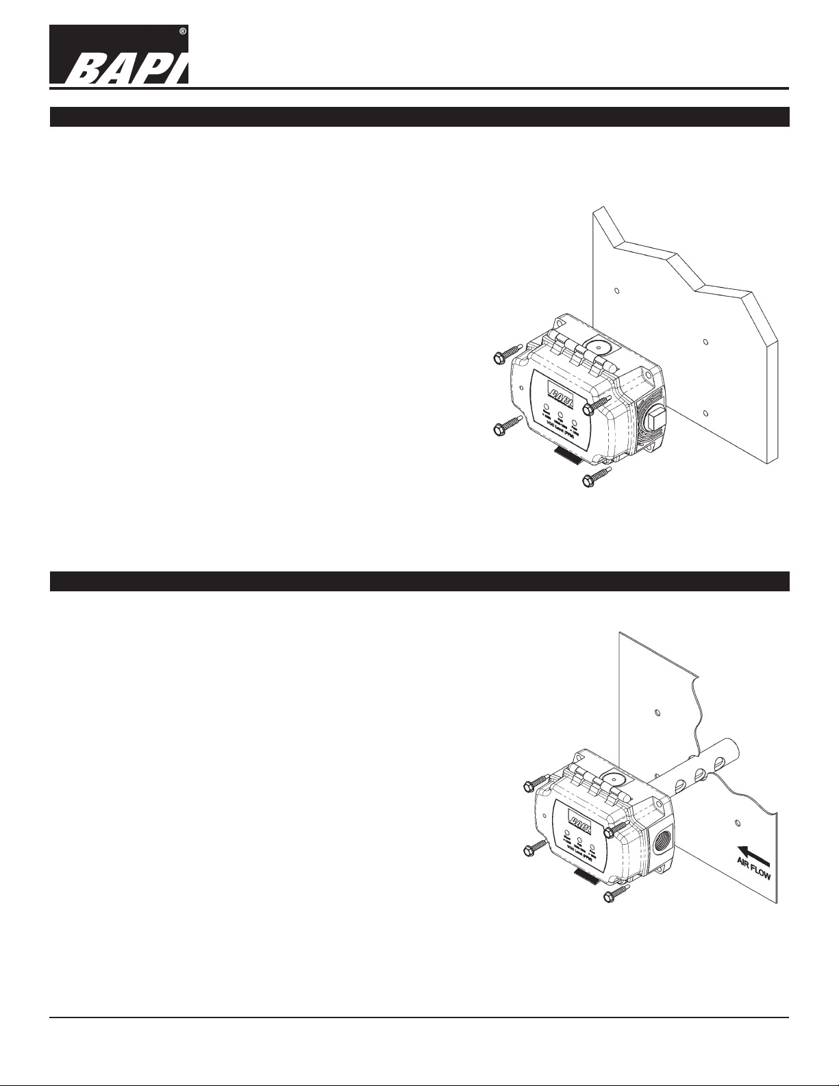
Rough Service Unit Mounting
Mount the Rough Service sensor on a solid, non-vibrating surface. Wall mounting in a room should be 3 to 5 feet
above oor level. The Rough Service VOC transmitter may be mounted in any orientation. If you are mounting
inside a duct or mixing box, mount with the latch facing into the moving air.
Refer to local codes for further sensor/transmitter installation
information. See BAPI’s “Coverage Area” Application Note for
further mounting recommendations. To get to this application
note, go to www.bapihvac.com, select “Resource Library” from
the banner. Click on “Application Notes” then scroll down the
page to the heading “Air Quality Related” and chose “Coverage
Area and Mounting Recommendations for BAPI Indoor Air
Quality Sensors”.
1. BAPI recommends #10 (provided) screws of a type and
length suitable for the mounting surface. Four mounting
screws keeps the box from twisting, twisting may prevent the
latch from operating properly. A pilot-hole makes mounting
easier. Use the enclosure mounting feet to mark the pilothole locations.
2. Snug up the screws so that the foam backing is depressed
but do not over-tighten or strip the screw threads.
3. Place the provided #6 screws into the holes on each site of
the lid latch to make the cover tamper resistant.
Fig. 4: Mounting the Rough Service
sensor to a wall
Duct Unit Mounting
1. BAPI recommends placing the sensor in the middle of the duct
wall, away from stratied air, to achieve the best reading. The unit
should also be a minimum of 3 duct diameters from an elbow,
damper or other duct restriction.
2. Drill a 1” hole for the aspiration probe.
3. Position the box so that airow is directly into the holes on
one side of the aspiration probe. There are no upstream or
downstream holes, the air direction is not important.
4. Mount the enclosure to the duct using BAPI recommended #10
screws (provided) through a minimum of two of the mounting feet
on opposite corners. A 1/8” pilot screw hole in the duct makes
mounting easier. Use the enclosure mounting feet to mark the
pilot-hole locations.
5. Snug up the screws until the foam backing is compressed about
50% to prevent air leakage but do not over-tighten.
6. Use the provided #6 screws to secure the cover for IP66 rating.
7. BAPI recommends sealing the conduit opening with berglass
insulation.
Fig. 5: Duct unit mounting
Specications subject to change without notice.
2 of 6
Page 3
VOC Duct and Rough Service Sensor
Installation & Operating Instructions
rev. 06/05/1840699_ins_VOC_3LED_BB
Termination
BAPI recommends using twisted pair of at least 22AWG and sealant lled connectors for all wire connections. Larger
gauge wire may be required for long runs. All wiring must comply with the National Electric Code (NEC) and local codes.
BAPI recommends wiring the product with power disconnected. Proper supply voltage, polarity and wiring
connections are important to a successful installation. Not observing these recommendations may damage
the product and void the warranty.
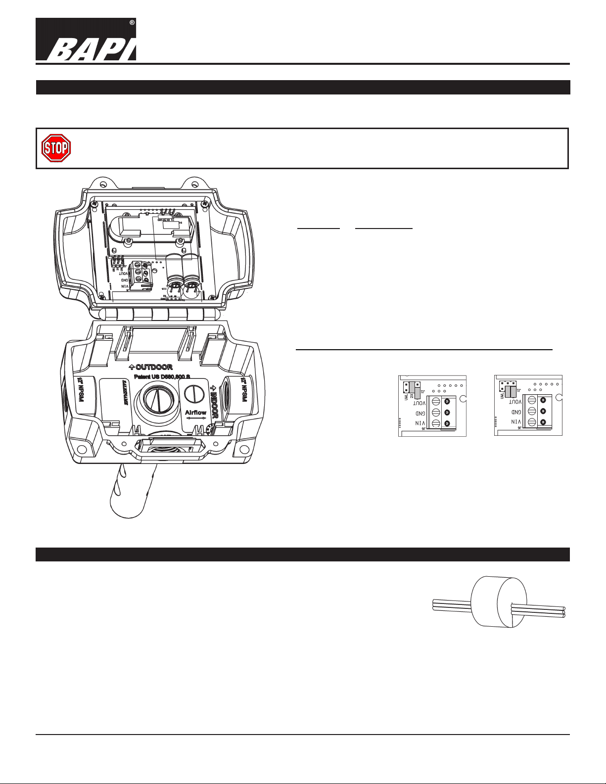
Terminal Description
VIN
..............Power, referenced to GND
12 to 24 VDC, 35 mA Peak
18 to 24 VAC, 4 VA Peak
GND
............To controller Ground [GND or Common]
..........Voltage Output, VOC Signal (0 to 2,000 ppm),
VOUT
referenced to GND
The VOC outputs
may be eld
congured for 0
to 5 VDC or 0 to
10 VDC outputs
at any time. Set
the jumpers on
J1 as shown in
Fig. 7: J1 set for 0
to 10 VDC output
Figures 7 and 8.
Fig. 6: Circuit board on open unit
Keeping the Enclosure Air Tight After Termination
For the sensor to work correctly, the wiring entrance must remain air tight. If the
VOC transmitter is mounted to a hollow wall and wired through its back, or wired
with conduit, it is possible that a draft of clean air may ll the enclosure through
the wiring opening. This draft may prevent the unit from measuring ambient
VOCs. BAPI recommends either a liquid-tight tting or plugging the conduit at the
enclosure.
• Liquid-Tight Fitting – BAPI’s Liquid-Tight Fitting (BA/LTF) allows wire cables of
0.1 to 0.3 inch outside diameter to enter the box. Tightening the collar onto the wire
cable keeps the wiring entrance air tight.
Fig. 8: J1 set for 0
to 5 VDC output
Fig. 9:
Wires Through Foam Plug
• Conduit – Included with the VOC transmitter is a foam plug to seal the ½ inch EMT. Place the wires into the plug as
shown in Fig. 9 and then insert the plug into the conduit sealing the conduit.
Specications subject to change without notice.
3 of 6
Page 4

VOC Duct and Rough Service Sensor
Installation & Operating Instructions
rev. 06/05/1840699_ins_VOC_3LED_BB
Sensor Start-Up
Do not set the control parameter to a VOC limit until the VOC sensor has been installed for a week. The rst few days
of install may provide different readings compared to several days later.
At each power up, the sensor enters the start-up period for 15 minutes. The VOC output will follow the timing shown in
Figure 10. During the start-up period, an optional verication/commissioning test, described below, may be performed.
This test is not mandatory. It is necessary only if building commissioning requires sensor verication or if verication of
VOC output is required for later troubleshooting.
Fig. 10: Sensor Start-up Timeline
Optional Sensor Performance Verication and Commissioning
BAPI’s VOC sensor contains an adaptive, self adjusting, Volatile Organic Compound (VOC) sensor element that
provides a CO
Demand Control Ventilation algorithm, ventilation using this sensor will achieve true indoor air quality and not just CO
dilution.
The fundamental performance criterion of the VOC sensor element is its dynamic sensing range. The VOC sensor
element requires a minimum dynamic range of 30% for proper operation. During BAPI’s verication/commissioning
test, the dynamic range is tested.
BAPI recommends installing the sensor and powering it for at least 48 hours before the rst verication test is
performed. BAPI further recommends ventilating the space such that the sensor reads 750 ppm or less CO
equivalent before any verication test is performed. Wait at least one hour before repeating the test.
equivalent control signal output. When incorporated into a control strategy based on ASHRAE’s
2
2
2
1. Start Automatic Verication/Commissioning Test
A. Remove sensor power for at least one minute and reapply. The VOC sensor will set the VOC output to zero
volts. (Power ON in Fig. 10)
B. Wait four minutes fteen seconds.
C. The VOC sensor will set the VOC output voltage to 5% of full scale (0.25 VDC for 0 to 5 VDC, 0.5 VDC or 0 to
10 VDC outputs).
D. The 5% output voltage conrms that the VOC sensor is in its verication/commissioning test. (Apply Test Gas
in Fig. 10.)
2. Apply Verication Stimulus
A. Apply the stimulus gas during the rst minute after the output voltage is set to 5% (See Stimulus Preparation
and Application section on next page).
B. Read and record the VOC output voltage approximately 2 to 4 minutes following the stimulus gas application to
determine the dynamic range measurement. (Dynamic Range Estimate period in Fig. 10)
C. Use the graph in Fig. 12 to determine dynamic range.
3. Termination of Verication Mode
A. For the last 7 minutes of the start-up period, the sensor adapts to its ambient environment. The VOC sensor
will maintain its output voltage at 450 ppm CO2 equivalent.
B. At 15 minutes the VOC sensor will terminate the start-up period and begin normal operation.
C. The VOC output will now report the VOCs present as CO2 equivalents.
4. Result Analysis and Recommendations
The VOC algorithm requires a dynamic range of greater than 30% for proper operation. Sensors reporting a
dynamic range of 30% or less should be considered for replacement. (See Fig. 12)
Specications subject to change without notice.
4 of 6
Page 5

VOC Duct and Rough Service Sensor
Installation & Operating Instructions
Stimulus Preparation and Application for Dynamic Range Testing
Place 50ml of Isopropyl Alcohol (70% minimum) into a 200ml bottle (2oz in an
8oz bottle) with stopper and allow to reach room temperature (65° to 80°F, 18° to
27°C), a minimum of 15 minutes.
1. Using a medical grade syringe, remove the stopper from the alcohol bottle,
place the tip of the syringe at least half-way into the bottle and withdraw a 60
ml sample of the ALCOHOL VAPOR. (NO LIQUID)
2. Replace the stopper on the alcohol bottle.
3. Place the end of the syringe under, or into the bottom ventilation slot of the
VOC monitor’s housing.
4. Empty the syringe into the sensor using one continuous motion. Compare
the sensor output to the Dynamic Range chart below to verify acceptable
operation. Sensors reporting a dynamic range of 30% or less should be
considered for replacement.
rev. 06/05/1840699_ins_VOC_3LED_BB
Fig. 11: Alcohol Bottle
and Syringe included in
the VOC Verication Kit
(BA/VOC-KIT)
Fig. 12: Acceptable Dynamic Range Output Graph
Specications subject to change without notice.
5 of 6
Page 6

Diagnostics
VOC Duct and Rough Service Sensor
Installation & Operating Instructions
rev. 06/05/1840699_ins_VOC_3LED_BB
Possible Problems:
General Troubleshooting
Incorrect VOC Reading
Possible Solutions:
- Determine that the input is set up correctly in the controller and BAS
software.
- Check wiring at the sensor and controller for proper connections. If
there is corrosion on any terminations, clean off the corrosion, re-strip
the interconnecting wire and reapply the connection. In extreme cases,
replace the controller, interconnecting wire and/or sensor.
- Label the VOC sensor wire terminals at the sensor and controller ends.
Disconnect the wires and measure the resistance from wire-to-wire
with a multimeter. The meter should read greater than 10 Meg-ohms,
open or OL depending on the meter. Short the wires at one end and
measure the resistance from wire-to-wire at the other end. The meter
should read less than 10 ohms (22 gauge or larger, 250 feet or less). If
either test fails, replace the wire.
- Check the power supply and controller voltage supply.
- Disconnect sensor and check power wires for proper voltage (see
power specs).
- Wait 15 minutes after a power interruption.
- Check all software parameters.
- Determine if the sensor is exposed to an external environment different
from the room (conduit draft).
Specications
Power:
12 to 24 VDC, 35 mA Peak
18 to 24 VAC, 4 VA Peak
VOC Sensor:
Micro-machined Metal Oxide
Mounting:
Duct or Surface Mount - screws provided
VOC Detection Range:
0 to 2,000ppm CO
Equivalent, Analog Output
2
Response Time:
Less Than 60 Seconds (after start-up)
Start-up Time:
15 minutes
Operating Environment:
32 to 122°F (0 to 50°C)
5 to 95%RH non-condensing
Analog Outputs:
0 to 5, or 0 to 10VDC >4KΩ impedance
LED VOC CO2 Equivalent Indicator:
Good, Green < 1,000 ppm
Fair, Yellow = 1,000 to 1,500 ppm
Poor, Red > 1,500 ppm
Material:
ABS Plastic, Material Rated UL94V-0
Certications:
RoHS
Warranty Period:
Five years from manufacture date
Specications subject to change without notice.
6 of 6
 Loading...