

Page 1
*
Thermobuffer Temperature Transmitters
BA/T#- TB Temperature Transmitter
Installation and Operation Instructions
20898_ins_Thermobuffer_Active
Overview
The BA/T#-TB is for measuring the temperature in walk-in-freezers or refrigerators with a wall or hanging bracket sensor.
The buffers are made in different lengths and are made to be lled with food grade glycol to slow down the temperature
response to more closely simulate the contents of the freezer or refrigerator.
The BA/T#-TB transmitter is available in
common temperature ranges and 2-wire, 4-20mA or voltage signaling as shown in the specications. The mounting enclosure styles come in NEMA 4 plastic or hanging bracket with the buffers available in stainless steel or aluminum to t any
application.
Identication
rev. 06/29/15
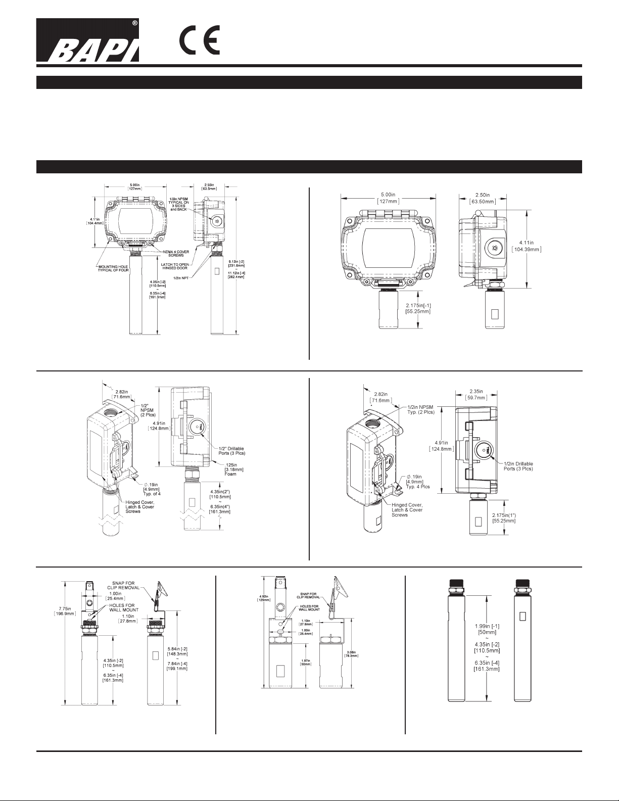
Fig 1: 2” & 4” Thermobuffer in a BAPI-Box
(BB) Enclosure
Fig 3: 2” & 4” Thermbuffer in a
BAPI-Box 2 (BB2) Enclosure
Fig 2: 1” Thermobuffer in a BAPI-Box (BB) Enclosure with
Plastic Threaded Fitting
Fig 4: 1” Thermobuffer in a BAPI-Box 2 (BB2)
Enclosure with Plastic Threaded Fitting
Fig 5: 2” & 4”
Hanging Bracket
Thermobuffer (Transmitter is
ordered and mounted separately.)
Fig 6: 1” Hanging Bracket Thermobuffer
(Transmitter is ordered and
mounted separately.)
Specications subject to change without notice.
Fig 7: No Box (NB) Thermobuffer
(Transmitter is ordered and
mounted separately.)
1 of 4
Page 2
20898_ins_Thermobuffer_Active
Assembly & Installation
Thermobuffer Temperature Transmitters
BA/T#- TB Temperature Transmitter
Installation and Operation Instructions
rev. 06/29/15
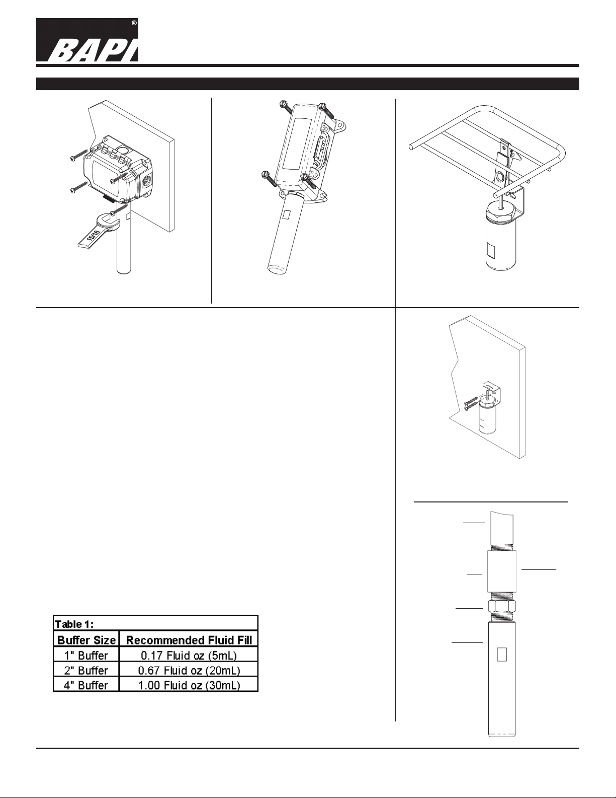
Fig 8: 2” & 4” Thermobuffer in a BAPI-Box
(BB) Enclosure Installation
Fig 9: 2” & 4” Thermobuffer in a BAPI-Box 2
(BB2) Enclosure Installation
1 Fill the buffer with the appropriate amount of customer provided glycol
to the amount as dictated by table 1.
2 Wrap the probe threads with Teon tape with at least 4 wraps so a water
tight seal is established.
3 Insert the probe into the buffer and screw in for a secure water tight t.
4 Towel off excess uid which may leak out during assembly and check
for leaking. If the assembly leaks, a 15/16ths wrench may be used to
snug up the probe to the buffer. More tape may also be needed. The
use of food safe silicon may also be used.
5 Select a location on a wall or hanging from a wire rack near the contents
you wish to monitor.
6 Mount the Thermo Buffer with the buffer facing down (Probe on top).
Any other orientation is not recommended due to leaking concerns.
7 We recommend BAPI Box surface mounting be positioned over the
refrigerator wire way hole using the rear BAPI Box knock out. Pull the
wiring into the unit and terminate using sealant lled connectors. Best
practice is to caulk the wiring hole after the wiring is installed. Secure
with mounting screws and ensure that the foam backing compresses
to about 50% of its thickness to make a gasket type seal against the
surface.
Fig 10: 1” Hanging Bracket Rack
Fig 11: 1” Hanging Bracket Wall Installation
1/2” NPT Pipe
(Customer Provided)
1/2” NPT Nipple
(Customer Provided)
BAPI Sensor
Installation
(Transmitter Mounted Externally)
Note: Customer Provided Screws
•
•
•
Termination
Within
•
Wire
Pipe
Specications subject to change without notice.
BAPI Buffer
Fig 12:
No Box (NB)
Thermobuffer
Installation
(Transmitter
Mounted Externally)
•
2 of 4
Page 3

Thermobuffer Temperature Transmitters
BA/T#- TB Temperature Transmitter
Installation and Operation Instructions
20898_ins_Thermobuffer_Active
Wiring & Termination
BAPI recommends using twisted pair of at least 22AWG and sealant lled connectors for all wire connections. Larger gauge wire
may be required for long runs. All wiring must comply with the National Electric Code (NEC) and local codes. Do NOT run this
device’s wiring in the same conduit as high or low voltage AC power wiring. BAPI’s tests show that inaccurate signal levels are
possible when AC power wiring is present in the same conduit as the sensor wires.
rev. 06/29/15
Fig. 13: Typical RTD 4 to 20 mA Transmitter with Flying Leads
Fig. 15: Typical Thermistor 4 to 20mA Transmitter
Fig. 14: Typical RTD 4 to 20mA Transmitter with Terminals
Fig. 16: Typical Thermistor Voltage Transmitter
Diagnostics
Problems: Possible Solutions:
•
Unit will not operate. - Measure the power supply voltage by placing a voltmeter across the transmitter’s (+) and
- Check if the RTD wires are physically open or shorted together and are terminated to the
- Measure the physical temperature at the temperature sensor’s location using an accurate
(-) terminal. Make sure that it matches the drawings above and power requirements in the
specications.
transmitter.
temperature standard. Disconnect the temperature sensor wires and measure the
temperature sensor’s resistance with an ohmmeter. Compare the temperature sensor’s
resistance to the appropriate temperature sensor table on the BAPI web site.
• The reading is incorrect in the controller.
- For a 4-20mA current transmitter measure the transmitter current by placing an ammeter
Voltage Temperature Equation
T = TLow + (V x TSpan)
VSpan
T = Temperature at sensor
TLow = Low temperature of span
THigh = High temperature of span
TSpan = THigh - TLow
VLow = Low transmitter voltage
usually=(0, 1 or 2v)
VHigh = High transmitter voltage
usually=(5 or 10v)
VSpan = VHigh - VLow
V = Signal reading in volts
- Determine if the input is set up correctly in the controllers and BAS software.
in series with the controller input. The current should read according to the “4-20mA
Temperature Equation” shown below.
- For a voltage transmitter, measure the signal with a volt meter (Orange or Orange/Black to
Black). The signal should read according to the “Voltage Temperature Equation” shown below.
4-20mA Temperature Equation
T = TLow + (A -4) x (TSpan)
16
T = Temperature at sensor
TLow = Low temperature of span
THigh = High temperature of span
TSpan = THigh - TLow
A = Signal reading in mA
Specications subject to change without notice.
3 of 4
Page 4

20898_ins_Thermobuffer_Active
Specications
Thermobuffer Temperature Transmitters
BA/T#- TB Temperature Transmitter
Installation and Operation Instructions
rev. 06/29/15
RTD Transmitter
Power Required: 7 to 40VDC
Transmitter Output: 4 to 20mA, 850Ω@24VDC
Output Wiring: 2 wire loop
Output Limits: <1mA (short), <22.35mA (open)
Span:
Zero:
Zero & Span Adjust: 10% of span
Accuracy: ±0.065% of span
Linearity: ±0.125% of span
Power Output Shift: ±0.009% of span
RTD Sensor: 2 wire Platinum (Pt), 385 curve
Transmitter Ambient -4 to 158ºF(-20 to 70ºC)
0 to 95% RH, Non-condensing
Thermistor Transmitter
Supply Voltage:
10 to 35 VDC (0 to 5 VDC or 4 to 20 mA Outputs)
15 to 35 VDC (0 to 10 VDC Output)
12 to 24 VAC (0 to 5 VDC Outputs)
15 to 24 VAC (0 to 10 VDC Output)
Transmitter Output: 4 to 20mA, 700Ω@24VDC
0 to 5 & 0 to 10VDC, 10KΩ min
Output Wiring: 2 & 3 wire (See wiring detail on pg. 3)
Transmitter Limits: -40 to 185ºF, (-40 to 85ºC)
Accuracy: ±1.015ºC, from (0 to 65ºC)
Linearity: ±0.065ºC, from (0 to 65ºC)
Resolution: Span/1024
Thermistor Sensor: 10K-2 Thermistor, 10KΩ @77ºF
Transmitter Ambient: 32 to 158ºF, (0º to 70ºC)
0 to 95% RH, Noncondensing
Thermistor: 10K-2,Thermal Resistor (Bare Sensor)
Accuracy (Std): ±0.36ºF, (±0.2ºC)
Accuracy (High): ±0.18ºF, (±0.1ºC), [XP] option
Stability: < 0.036ºF/Year, (<0.02ºC/Year)
Heat Dissipation: 2.7 mW/ºC
Probe Range: -40º to 221ºF (-40º to 105ºC)
Wire Colors:
Standard: Yellow/Yellow (no polarity)
High Acc. [XP]: Yellow/Yellow (no polarity)
RTD:
Platinum (Pt): 100Ω and 1KΩ @0ºC, 385 curve,
Pt Accuracy (Std): 0.12% @Ref, or ±0.55ºF, (±0.3ºC)
Pt Accuracy (High): 0.06% @Ref, or ±0.277ºF,
(±0.15ºC), [A]option
Pt Stability: ±0.25ºF, (±0.14ºC)
Pt Self Heating: 0.4 ºC/mW @0ºC
Pt Probe Range: -40º to 221ºF, (-40 to 105ºC)
Wire Colors:
1KΩ, Class B Orange/Orange (no polarity)
1KΩ, Class A Orange/White (no polarity)
100Ω, Class B Red/Red (no polarity)
100Ω, Class A Red/Red-w/black stripe (no polarity)
Sensitivity: Approximate @ 32ºF (0ºC)
Thermistor: Non-linier (See www.bapihvac.com,
click “Sensor Specs”)
RTD (Pt): 3.85Ω/ºC for 1KΩ RTD
0.385Ω/ºC for 100Ω RTD
Min. 30ºF (17ºC), Max 1000ºF, (555ºC)
Min. -148°F (-100°C), Max 900ºF (482ºC)
Resistance Temp Device (Bare Sensor)
General color code (other colors possible)
Lead Wire: 22awg stranded
Insulation: Etched Teon, Plenum rated
Probe: 304 Stainless Steel (SS), 0.25” OD
Probe Process Connection:
-TB 304 SS Double threaded ½” NPT
Probe Length: Probe tip to thread start
1” 0.75”
2” 3.5”
4” 5.5”
Buffer Chamber Dimensions:
1” Buffer 2.75”H x 1” Dia
2” Buffer 5.1”H x 1” Dia
4” Buffer 7.1”H x 1” Dia
Mounting:
Plastic Box 4 extension tabs (ears), 7/16” hole,
Hanging Bracket
Enclosure Types:
No Box -NB, intended for direct ½” NPT pipe mount
BAPI-Box: -BB, w/ four ½” NPSM & one ½” drill-out
BAPI-Box 2: -BB2, w/ three ½” NPSM & three ½” drill-outs
Hanging Bracket -HB, Intended to hang from shelving
Enclosure Ratings:
No Box -NB, No Rating
BAPI-Box -BB, NEMA 4, IP66
BAPI-Box 2 -BB2, NEMA 4, IP66
Hanging Bracket -HB, No rating
Enclosure Materials:
BAPI-Box -BB, Polycarbonate, UL94V-0, UV rated
BAPI-Box 2 -BB2, Polycarbonate, UL94V-0, UV rated
Hanging Bracket -HB, 304 Satinless Steel bracket and clip
Buffer Chamber Construction:
M-304 Machined 304 Stainless Steel, 0.7” core
MAL Machined Aluminum, 0.7” core
Liquid Fill: Food Grade Glycol (Customer provided)
1” Buffer 5 mL
2” Buffer 20 mL
4” Buffer 30 mL
Color:
BAPI-Boxes Warm White (beige)
SS Buffer Polished Stainless Steel
Aluminum Buffer Wire Brushed Aluminum
Ambient (Enclosure):
BAPI-Box -BB, -40 to 185ºF (-40 to 85ºC)
BAPI-Box & BAPI -BB2, -40 to 185ºF (-40 to 85ºC)
NB, w/ TB sensor -NB, -40 to 212ºF (-40 to 100ºC)
Hanging Bracket -HB, -40 to 122ºF (-40 to 50ºC)
Agency:
Pt= DIN43760, IEC Pub 751-1983,
JIS C1604-1989
SS bracket with 1/8” holes or 3/8” spring clip
0 to 100% RH, Non-condensing
RoHS,
Specications subject to change without notice.
4 of 4
 Loading...