

Page 1
Temperature Transmitters
Installation & Operating Instructions
9518_ins_txmtr
rev. 10/12/15
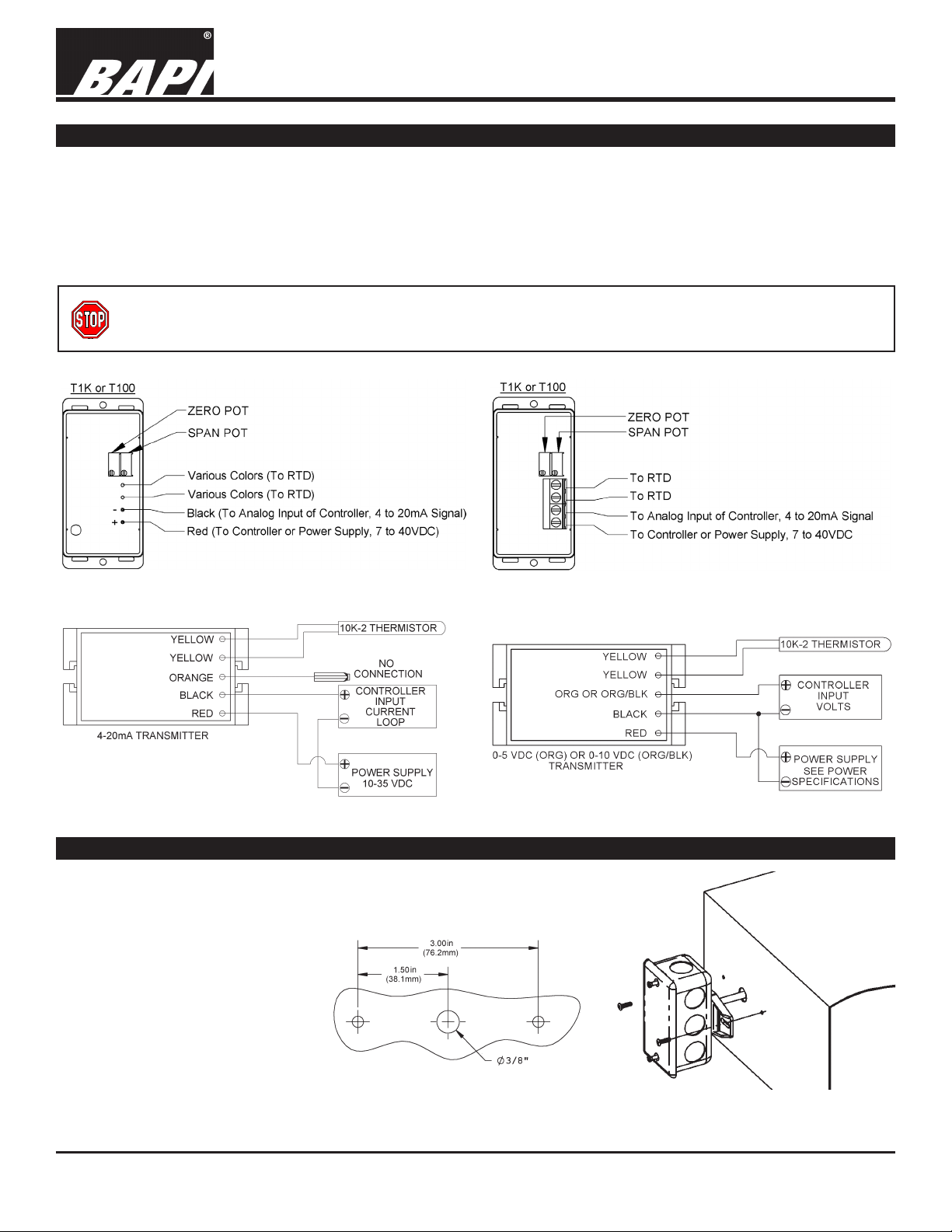
Termination
BAPI recommends using twisted pair of at least 22AWG and sealant lled connectors for all wire connections.
Larger gauge wire may be required for long runs. All wiring must comply with the National Electric Code (NEC) and
local codes. Do NOT run this device’s wiring in the same conduit as AC power wiring of NEC class1 or NEC class 2,
NEC class 3 or with wiring used to supply highly inductive loads such as motors, contactors and relays.
BAPI’s tests show that uctuating and inaccurate signal levels are possible when AC power wiring is present in the
same conduit as the signal lines.
BAPI recommends wiring the product with power disconnected. Proper supply voltage, polarity, and
wiring connections are important to a successful installation. Not observing these recommendations may
damage the product and will void the warranty.
Fig. 1: Typical 4 to 20mA RTD Transmitter w/ Flying Leads
Fig. 3: Typical 4 to 20mA Thermistor Transmitter
Fig. 2: Typical 4 to 20mA RTD Transmitter w/ Terminals
Fig. 4: Typical Thermistor Voltage Transmitter
Junction Box (JB) Mounting
The Junction Box mount is intended for indoor mounting in equipment
rooms, plenums or occupied spaces. Fig. 6 shows a typical Junction Box
mounting in an air duct. BAPI
recommends using #8 sheet metal
screws that need 1/8” pilot holes to
attach the sensor to the duct.
After placing the sensing element
in the duct, secure the mounting
ange to the duct; center the
plastic tting holding the probe in
the mounting hole. Make sure that
the foam seals the hole; do not
over tighten the screws.
Fig. 5: Junction Box Duct
Mounting Holes
Fig. 6: Junction Box Duct Installation
Specications subject to change without notice.
1 of 6
Page 2
Temperature Transmitters
Installation & Operating Instructions
9518_ins_txmtr
rev. 10/12/15
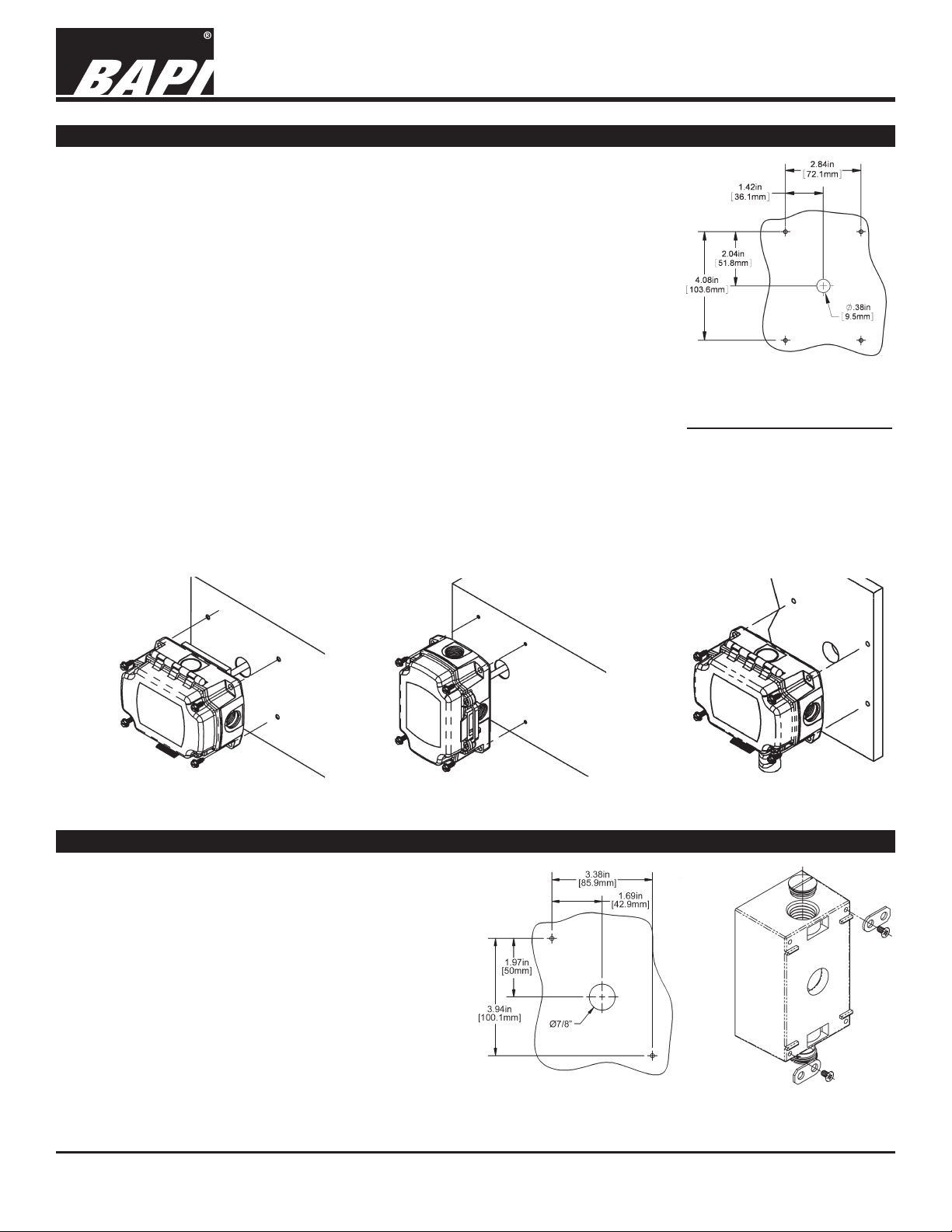
BAPI-Box (BB) Mounting
The BAPI-Box Enclosure is watertight and carries an IP66 rating (similar to a NEMA
4X rating) when the included screws are fastened on the latch. The BAPI-Box is
made of high impact, UV-resistant polycarbonate and features a hinged cover with
multiple knockouts. It is available for the full line of BAPI temperature sensors.
Duct Mounting
Mount the unit to its mounting surface with four #10 screws through the holes in the
mounting feet. #10 sheet metal screws require 5/32” (4mm) pilot holes. For concrete
or cinder block, drill four 5/32” (4mm) holes, 1-3/4” (45mm) deep. Make sure that all
screws are started in their holes before tightening evenly. If unit has a foam gasket,
only squeeze to about 1/2 of its original thickness. Be sure to seal conduit connector
threads and holes in mounting surface to maintain the integrity of the box.
Outside Mounting
The sensor must be mounted in the shade away from building windows, doors or
vents. The ideal shaded location in the Northern hemisphere is on the North side of
Fig 6: BAPI-Box enclosure
mounting holes, rotate 90°
for horizontal mount
the building. In the Southern hemisphere the South side of the building is ideal. The
probe should point down and the unit should mounted between 4 feet above the ground/roof and one foot minimum
below the eave.
Drill the mounting holes and mount as shown in the Fig. 9. Snug the mounting screws to compress the foam backing to about 50% of its original thickness to make a good seal to the wall surface. Route the wires into the box and
terminate with sealant lled connectors. Best practice is to caulk the wiring hole after the wiring is installed. Close
the cover of the BAPI-Box and secure with provided cover screws.
Fig 7: BAPI-Box Duct
Horizontal Installation
Fig 8: BAPI-Box Duct
Vertical Installation
Weatherproof (WP) Enclosure Mounting
The weatherproof enclosure is intended for outdoor
or equipment room mounting. Use the mounting tabs
provided to mount the enclosure as shown in gures
10-13. DO NOT drill screw holes through the back
wall of the box. This destroys the integrity of the box
and may void the warranty.
Duct Mounting
BAPI recommends using #8 sheet metal screws that
need 1/8” pilot holes to attach the sensor to the duct.
After placing the sensing element in the duct, secure
the mounting tabs to the duct; center the plastic
tting holding the probe in the mounting hole. Be
Continued on next page...
Specications subject to change without notice.
Fig. 10: Weatherproof
Enclosure mounting holes
Fig 9: BAPI-Box Outdoor Air
Installation
Fig. 11: Weatherproof
Enclosure Mounting Tabs
2 of 6
Page 3

Temperature Transmitters
Installation & Operating Instructions
9518_ins_txmtr
rev. 10/12/15
Weatherproof (WP) Enclosure Mounting continued...
sure that the foam seals the hole; do not over tighten the screws. Place the foam gasket between the cover and the
box before securing the cover in place with the screws provided. T
o keep water out of the box, be sure to coat the
threads of the box plugs or conduit connectors with caulk before screwing them into the enclosure.
Outside Mounting
The sensor must be mounted in the shade away from building windows, doors or vents. The ideal shaded location
in the Northern hemisphere is on the North side of the building. In the Southern hemisphere the South side of the
building is ideal. The probe should point down and the unit should mounted between 4 feet above the ground/roof
and one foot minimum below the eave.
Drill the mounting holes and mount as shown in the
Fig. 13. Snug the mounting screws to compress the
foam backing to about 50% of its original thickness
to make a good seal to the wall surface. Route the
wires into the box and terminate with sealant lled
connectors. Best practice is to caulk the wiring hole
after the wiring is installed. Close the cover of the
enclosure and secure with provided cover screws.
Note: Air temperature units are shown. Temperature
and humidity units are available in doublegang
weatherproof enclosures only.
Fig. 12: Weatherproof
Enclosure Duct Installation
Fig. 13: Weatherproof
Enclosure Outside Installation
Weather Tight (EU) Enclosure Mounting
The Weather Tight (EU) Enclosure is available
in ABS plastic for indoor applications and UVlight stabilized plastic for outdoor applications.
Duct Mounting
Figure 15 shows a typical Weather Tight
enclosure mounting in an air duct. BAPI
recommends using #8 sheet metal screws
that need 1/8-inch pilot holes. After placing
the sensing element in the duct, secure the
mounting feet to the duct; center the plastic
tting holding the probe in the mounting hole.
Fig. 14: Weather Tight
Enclosure Mounting Holes
Do not over tighten the screws but be sure
that the foam insulation makes an airtight seal.
Tighten the lid to two clicks when you are nished making terminations.
Outside Mounting
The sensor must be mounted in the shade away from building windows, doors or
vents. The ideal shaded location in the Northern hemisphere is on the North side
of the building. In the Southern hemisphere the South side of the building is ideal.
The probe should point down and the unit should mounted between 4 feet above
the ground/roof and one foot minimum below the eave.
Drill the mounting holes and mount as shown in the Fig. 9. Snug the mounting
screws to compress the foam backing to about 50% of its original thickness to
make a good seal to the wall surface. Route the wires into the box and terminate with sealant lled connectors. Best practice is to caulk the wiring hole after
the wiring is installed. Tighten the lid to two clicks when you are nished making
terminations.
Fig. 15: Weather Tight
Enclosure Duct Installation
Fig. 16: Weather Tight
Enclosure Outside Installation
Specications subject to change without notice.
Page 4

Temperature Transmitters
Installation & Operating Instructions
9518_ins_txmtr
rev. 10/12/15
Immersion Sensor Mounting
Place the thermowell into the pipe nipple using Teon tape and/or pipe dope. Tighten securely but do not over
torque. Insert the immersion sensor into the thermowell with the plastic tting screwing into the opening on the
thermowell. Tighten the immersion sensor snugly by hand without too much torque. Make sure that the tip of the
immersion sensor is in contact with the bottom of the thermowell. The unit is designed so that the temperature probe
moves slightly into the enclosure as the sensor hits the bottom of the well. Fig. 18 shows a Junction Box installation,
but Weatherproof, Weather Tight or BAPI-Box enclosures may be used as well.
Fig. 18: Cross section
of an immersion unit
Fig. 17: Transmitter mounted to the cover of a
Weatherproof Enclosure with an immersion probe
installation
Strap Sensor Mounting
Spring-Loaded Straps
The Spring-Loaded Strap Sensor is used when a large section
of insulation cannot be removed from a pipe. It accommodates
insulation of up to 2” thick and is sized for pipe diameters of 5 to
12.5”, including the insulation.
Cut a 1-1/4” diameter hole in the insulation and remove the
insulation from the hole down to the bare pipe. Be sure to remove all
insulation and debris from the hole. Place the copper pad on the end
of the spring-mounted foam into the hole and make sure it has good
physical contact with the pipe. Tighten the straps until the strapmounting bracket contacts the insulation.
Clamp-On Straps
Place the Clamp-On Strap Sensor on bare pipe, or a section of pipe
with the insulation removed. The clamp-on strap sensor is sized for
bare pipes of 2 to 4.5” in diameter.
Make sure that the copper pad on the foam is in good physical
contact with the pipe. Snug the straps so that the assembly does
not rotate around the pipe when moderate pressure is applied to the
Junction Box. Do not over tighten. You may place pipe insulation
over the whole assembly. Add another pipe clamp if needed.
Fig. 20 shows a Junction Box installation, but a BAPI-Box enclosure
may be used as well.
Fig. 19: Spring-Loaded Strap installation
Specications subject to change without notice.
Fig. 20: Clamp-On Strap installation
4 of 6
Page 5

Temperature Transmitters
Installation & Operating Instructions
9518_ins_txmtr
rev. 10/12/15
Wall Plate Mounting
The Stainless Steel Wall Plate is intended for indoor mounting
to a 2x4” Junction Box. Install a Junction Box as shown in the
Fig. 21. Terminate your wiring cables to the red and black wires,
preferably with sealant lled connectors. Secure the Wall Plate
to the Junction Box with the screws provided making sure that
the foam gasket on the back of the plate seals to the wall without
wrinkling the foam. The plate should not contact the wall.
Fig. 21: Wall Plate Transmitter Installation
Remote Probe Mounting
Mount Remote Probes as shown in the gures below with the wire connector down. Route the temperature probe
to the spot where you wish to measure the temperature. Best practice is to tie down the wire every two feet. Make
sure to caulk the upper screw-in plug on the Weatherproof enclosure. Center mounting hole shown is only used if
you are wiring through the mounting surface.
Fig. 22:
BAPI-Box
(BB)
Installation
Fig. 23: BAPI-Box (BB)
mounting holes
Fig. 24:
Weatherproof
(WP) Enclosure
Installation.
(See Fig. 11 for
Mounting Tab
installation.)
Fig. 25: Weatherproof (WP)
Enclosure mounting holes
Specications subject to change without notice.
Fig. 26:
Weather
Tight (EU)
Enclosure
installation
Fig. 27: Weather Tight (EU)
Mounting Template
5 of 6
Page 6

Temperature Transmitters
Installation & Operating Instructions
9518_ins_txmtr
rev. 10/12/15
Diagnostics
Possible Problems: Possible Solutions:
Unit will not operate. - Measure the power supply voltage by placing a voltmeter across
•
the transmitter’s (+) and (-) terminal. Make sure that it matches the
drawings above and power requirements in the specications.
- Check if the RTD wires are physically open or shorted together and are
terminated to the transmitter.
• Reading is incorrect in the controller. - Determine if the input is set up correctly in the controller and BAS
software.
- For a 4 to 20mA current transmitter measure the transmitter current
by placing an ammeter in series with the controller input. The current
should read according to the “4 to 20mA Temperature Equation” shown
below.
- For a voltage transmitter, measure the signal with a volt meter (Orange
or Orange/Black to Black). The signal should read according to the
“Voltage Temperature Equation” shown below.
Voltage Temperature Equation
T = TLow + (V x TSpan)
VSpan
T = Temperature at sensor
TLow = Low temperature of span
THigh = High temperature of span
TSpan = THigh - TLow
VLow = Low transmitter voltage
usually=(0, 1 or 2v)
VHigh = High transmitter voltage
usually=(5 or 10v)
VSpan = VHigh - VLow
V = Signal reading in volts
4-20mA Temperature Equation
T = TLow + (A -4) x (TSpan)
16
T = Temperature at sensor
TLow = Low temperature of span
THigh = High temperature of span
TSpan = THigh - TLow
A = Signal reading in mA
Specications subject to change without notice.
6 of 6
 Loading...