

Page 1
Temperature Sensor Transmitters
BA/(T100, T1K, T10K) Temperature Transmitters
Installation & Operating Instructions
22199_ins_T1K_T100_XMTR
Overview
6
The BA/T100 units are 4 to 20mA loop powered transmitters that can be ordered with separately purchased 100Ω (385)
platinum RTD. The BA/T1K units are 4 to 20mA loop powered transmitters that can be ordered with separately purchased
1KΩ (385) platinum RTD. The BA/T10K units are 4 to 20mA loop powered or 0 to 5VDC or 0 to 10VDC transmitters that can
be ordered with separately purchased 10K-2, 10KΩ type 2 thermistors. T100 and
terminals are available (-TS). Terminals are not available on the T10K units.
Identication
6
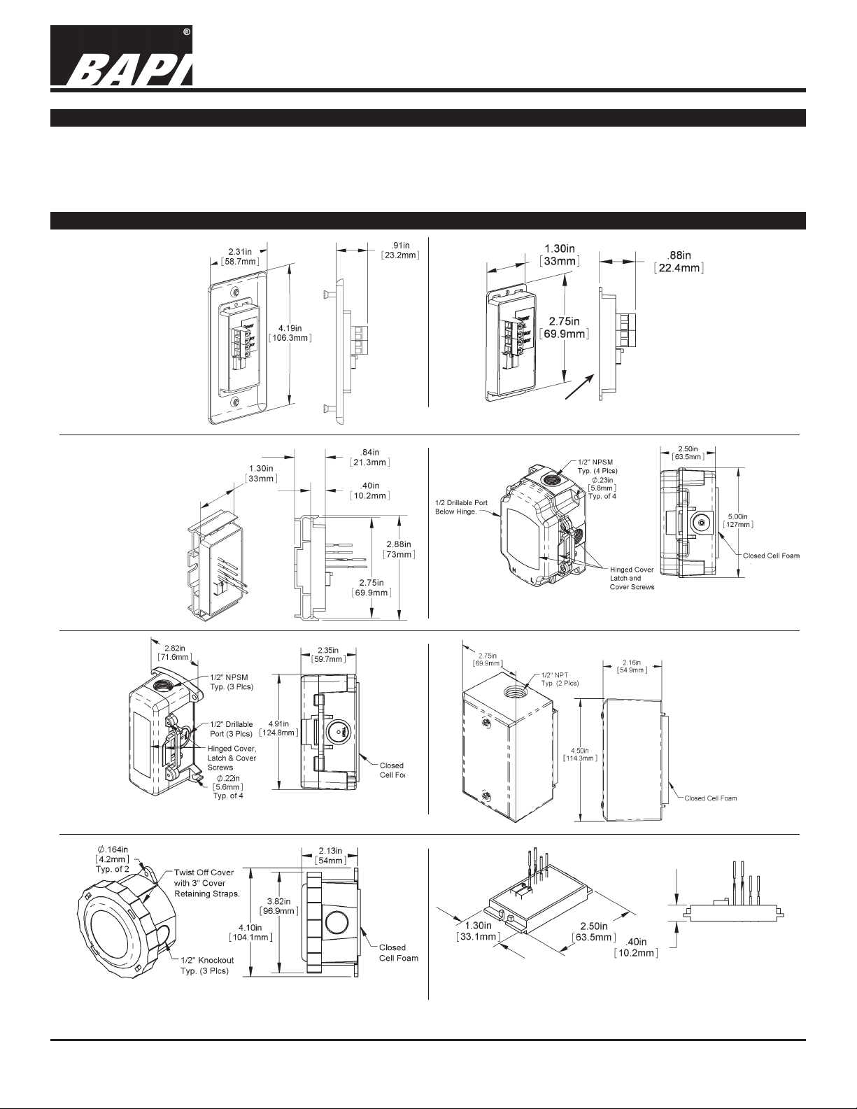
T1K transmitters come with ying leads but
Fig 1: Transmitter
with plate
(BA/T1x-XOR-TS)
Fig 2: Transmitter only
Peel off
mounting tape
(BA/T1x-XOR-STM-TS)
rev. 06/30/15
Fig 3: Transmitter with
Snaptrack
(BA/T1x-XOR-TRK)
Fig 5: Transmitter in BAPI-Box 2 (BA/T1x-XOR-BB2)
Fig 4: Transmitter in BAPI-Box (BA/T1x-XOR-BB)
Fig 6: Transmitter
in Weatherproof
Enclosure
(BA/T1x-XOR-WP)
Fig 7: Transmitter in Weather Tight Encl. (BA/T1x-XOR-EU)
Specications subject to change without notice.
Fig 8: Transmitter only - ts inside Weather Tight
Enclosure (BA/T1x-XOR-EUM)
1 of 4
Page 2
Temperature Sensor Transmitters
BA/(T100, T1K, T10K) Temperature Transmitters
Installation & Operating Instructions
22199_ins_T1K_T100_XMTR
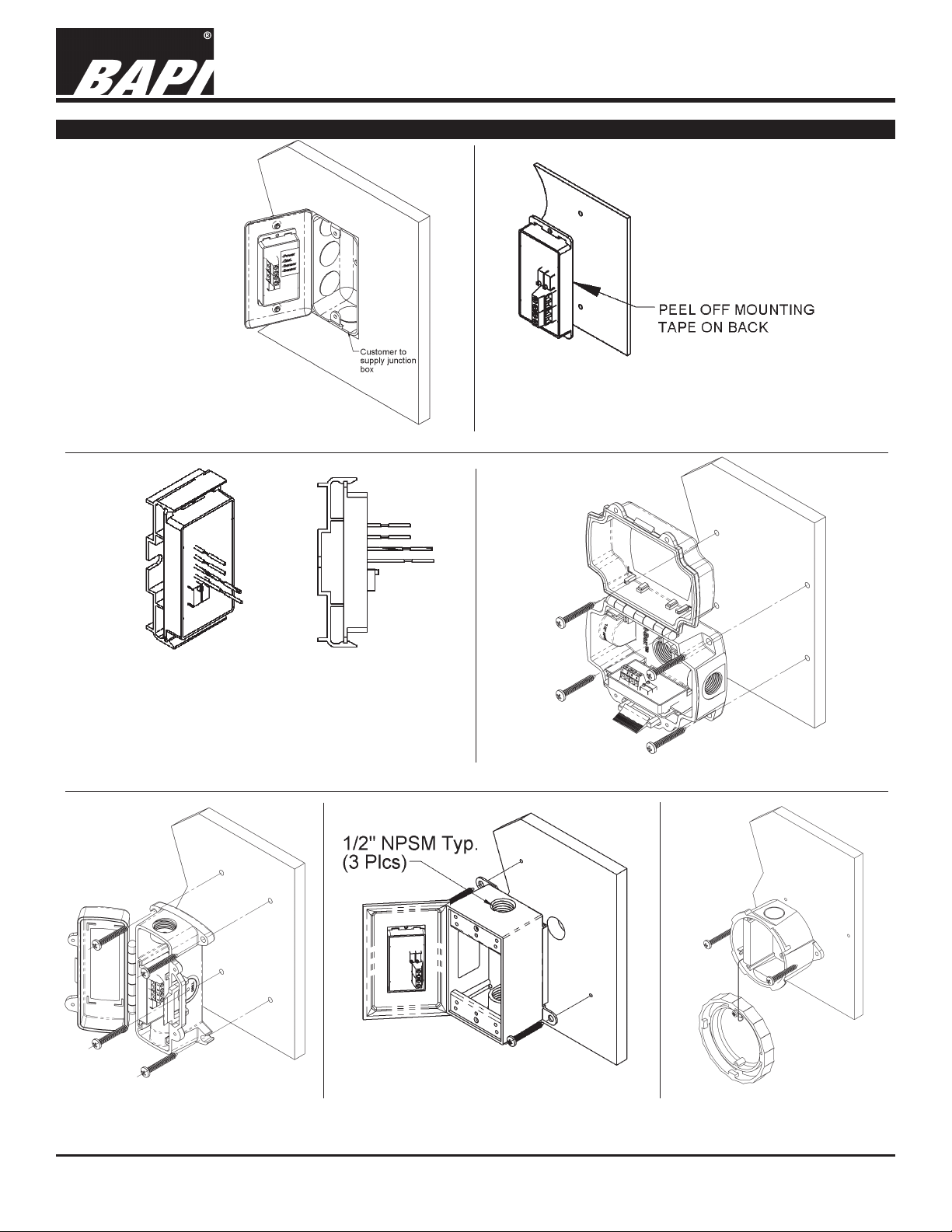
Mounting
6
Fig 9: Transmitter w/
plate mounted in a
Handy Box
Fig 10: Transmitter
with double stick mounting tape
rev. 06/30/15
1. Mount track with screws through the bottom
of the plastic track.
2. Insert one edge of the transmitter, then snap
the other edge in.
Fig 11: Transmitter in Snaptrack
Fig 13: Transmitter in a
BAPI-Box 2 Enclosure
Specications subject to change without notice.
Fig 12: Transmitter in a BAPI-Box Enclosure
Fig 14: Transmitter in a
Weatherproof Enclosure
Fig 15: Transmitter in a
Weather Tight Enclosure
2 of 4
Page 3

Temperature Sensor Transmitters
BA/(T100, T1K, T10K) Temperature Transmitters
Installation & Operating Instructions
22199_ins_T1K_T100_XMTR
Wiring & Termination
6
BAPI recommends using twisted pair of at least 22AWG and sealant lled connectors for all wire connections. Larger
gauge wire may be required for long runs. All wiring must comply with the National Electric Code (NEC) and local codes.
Do NOT run this device’s wiring in the same conduit as high or low voltage AC power wiring. BAPI’s tests show that inaccurate signal levels are possible when AC power wiring is present in the same conduit as the sensor wires.
rev. 06/30/15
Fig. 17: Typical
RTD 4 to 20mA
Transmitter with
Terminals
Fig. 18: Typical Thermistor
4 to 20mA Transmitter
Fig. 16: Typical
RTD 4 to 20 mA
Transmitter with
Flying Leads
Fig. 19: Typical Thermistor
Voltage Transmitter
Diagnostics
Possible Problems: Possible Solutions:
•
Unit will not operate. - Measure the power supply voltage by placing a voltmeter across the transmitter’s (+) and
- Check if the RTD wires are physically open or shorted together and are terminated to the
- Measure the physical temperature at the temperature sensor’s location using an accurate
(-) terminal. Make sure that it matches the drawings above and power requirements in the
specications.
transmitter.
temperature standard. Disconnect the temperature sensor wires and measure the
temperature sensor’s resistance with an ohmmeter. Compare the temperature sensor’s
resistance to the appropriate temperature sensor table on the BAPI web site.
• The reading is incorrect in the controller.
- For a 4-20mA current transmitter measure the transmitter current by placing an ammeter
Voltage Temperature Equation
T = TLow + (V x TSpan)
VSpan
T = Temperature at sensor
TLow = Low temperature of span
THigh = High temperature of span
TSpan = THigh - TLow
VLow = Low transmitter voltage
usually=(0, 1 or 2v)
VHigh = High transmitter voltage
usually=(5 or 10v)
VSpan = VHigh - VLow
V = Signal reading in volts
- Determine if the input is set up correctly in the controllers and BAS software.
in series with the controller input. The current should read according to the “4-20mA
Temperature Equation” shown below.
- For a voltage transmitter, measure the signal with a volt meter (Orange or Orange/Black to
Black). The signal should read according to the “Voltage Temperature Equation” shown below.
4-20mA Temperature Equation
T = TLow + (A -4) x (TSpan)
16
T = Temperature at sensor
TLow = Low temperature of span
THigh = High temperature of span
TSpan = THigh - TLow
A = Signal reading in mA
Specications subject to change without notice.
3 of 4
Page 4

Temperature Sensor Transmitters
BA/(T100, T1K, T10K) Temperature Transmitters
Installation & Operating Instructions
22199_ins_T1K_T100_XMTR
Secications
6
rev. 06/30/15
RTD Transmitter
Power Required: 7 to 40VDC
Transmitter Output: 4 to 20mA, 850Ω@24VDC
Output Wiring: 2 wire loop
Output Limits: <1mA (short), <22.35mA (open)
Span:
Zero:
Zero & Span Adjust: 10% of span
Accuracy: ±0.065% of span
Linearity: ±0.125% of span
Power Output Shift: ±0.009% of span
RTD Sensor: 2 wire Platinum (Pt), 385 curve
Transmitter Ambient -4 to 158ºF(-20 to 70ºC)
0 to 95% RH, Non-condensing
Thermistor Transmitter
Supply Voltage:
10 to 35 VDC (0 to 5 VDC or 4 to 20 mA Outputs)
15 to 35 VDC (0 to 10 VDC Output)
12 to 24 VAC (0 to 5 VDC Outputs)
15 to 24 VAC (0 to 10 VDC Output)
Transmitter Output: 4 to 20mA, 700Ω@24VDC
0 to 5 & 0 to 10VDC, 10KΩ min
Output Wiring: 2 & 3 wire (See wiring detail on pg. 3)
Transmitter Limits: -40 to 185ºF, (-40 to 85ºC)
Accuracy: ±1.015ºC, from (0 to 65ºC)
Linearity: ±0.065ºC, from (0 to 65ºC)
Resolution: Span/1024
Thermistor Sensor: 10K-2 Thermistor, 10KΩ @77ºF
Transmitter Ambient: 32 to 158ºF, (0º to 70ºC)
0 to 95% RH, Noncondensing
Thermistor: 10K-2,Thermal Resistor (Bare Sensor)
Accuracy (Std): ±0.36ºF, (±0.2ºC)
Accuracy (High): ±0.18ºF, (±0.1ºC), [XP] option
Stability: < 0.036ºF/Year, (<0.02ºC/Year)
Heat Dissipation: 2.7 mW/ºC
Probe Range: -40º to 221ºF (-40º to 105ºC)
Wire Colors:
Standard: Yellow/Yellow (no polarity)
High Acc. [XP]: Yellow/Yellow (no polarity)
RTD:
Platinum (Pt): 100Ω and 1KΩ @0ºC, 385 curve,
Pt Accuracy (Std): 0.12% @Ref, or ±0.55ºF, (±0.3ºC)
Pt Accuracy (High): 0.06% @Ref, or ±0.277ºF,
(±0.15ºC), [A]option
Pt Stability: ±0.25ºF, (±0.14ºC)
Pt Self Heating: 0.4 ºC/mW @0ºC
Pt Probe Range: -40º to 221ºF, (-40 to 105ºC)
Wire Colors:
1KΩ, Class B Orange/Orange (no polarity)
1KΩ, Class A Orange/White (no polarity)
100Ω, Class B Red/Red (no polarity)
100Ω, Class A Red/Red-w/black stripe (no polarity)
Min. 30ºF (17ºC), Max 1000ºF, (555ºC)
Min. -148°F (-100°C), Max 900ºF (482ºC)
Resistance Temp Device (Bare Sensor)
General color code (other colors possible)
Sensitivity: Approximate @ 32ºF (0ºC)
Thermistor: Non-linier - (See www.bapihvac.com,
click “Sensor Specs”)
RTD (Pt): 3.85Ω/ºC for 1KΩ RTD
0.385Ω/ºC for 100Ω RTD
Enclosure Types: (Part number designator in bold)
Box Cover Plate:
Weatherproof:
BAPI-Box:
BAPI-Box 2:
Weather Tight:
Transmitter Only:
XOR-EUM, No Enclosure
Enclosure Ratings: (Part number designator in bold)
Weatherproof: -WP, NEMA 3R, IP14
BAPI-Box: -BB, NEMA 4, IP66, UV Rated
BAPI-Box 2: -BB2, NEMA 4, IP66, UV Rated
Weather Tight: -EU, NEMA 4, IP66
Weather Tight: -EUO, NEMA 4, IP66, UV rated
Enclosure Material: (Part number designator in bold)
Weatherproof: -WP, Cast Aluminum, UV rated
BAPI-Box: -BB, Polycarbonate, UL94V-0, UV rated
BAPI-Box 2: -BB2, Polycarbonate, UL94V-0, UV rated
Weather Tight: -EU, ABS Plastic, UL94V-0
Weather Tight:
Ambient (Enclosure): 0 to 100% RH, Non-condensing
Weatherproof: -WP, 40ºF to 212ºF, (-40º to 100ºC)
BAPI-Box: -BB, -40ºF to 185ºF, (-40º to 85ºC)
BAPI-Box 2: -BB2, -40ºF to 185ºF, (-40º to 85ºC)
Weather Tight -EU, -EUO, -40ºF to 185ºF, (-40º to 85ºC)
Agency: RoHS
PT= DIN43760, IEC Pub 751-1983,
JIS C1604-1989
XOR, single gang box cover only.
XOR-WP, w/ two ½” FNPT entries, (Bell box)
XOR-BB, w/ four ½” NPSM & one ½” drill-out
XOR-BB2, w/ three ½” NPSM & three ½” drill-outs
XOR-EU, XOR-EUO, w/ two ½” knock-outs
XOR-STM, No Enclosure
-EUO, ASA (Geloy) Plastic, UL94V-0, UV rated
Specications subject to change without notice.
4 of 4
 Loading...