

Page 1
Extreme Temperature RTD Sensors
BA/1x[1,2,3] Temperature Sensor
Installation & Operating Instructions
8612_ins_RTD_EXTRM
Overview
The Extreme Temperature Sensor is made for thermowell mounting, direct insertion or remote probe mounting. The probe is made
of Stainless Steel and made in different lengths for a custom t. The RTD’s are available in 100Ω or 1KΩ 385 curve as shown in the
specications. The enclosures come in plastic or metal for both NEMA 3R and NEMA 4 applications and are all plenum rated.
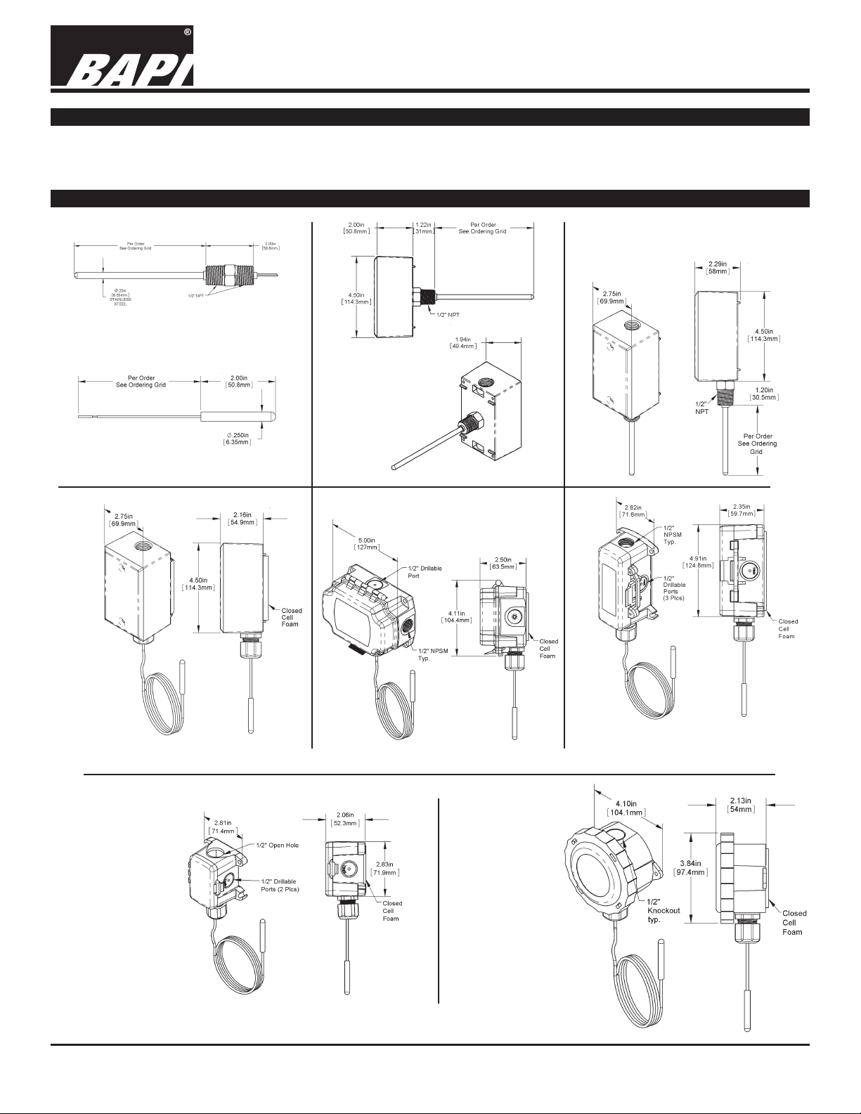
Identication
6
Fig. 4: Extreme Temp Immersion
with Weatherproof (WP) Enclosure,
Fig. 1: Extreme Temp Immersion Sensor
Fig. 3: Extreme
Temp Immersion
with Weatherproof
(WP) Enclosure,
Standard Mount
Outside Mount
rev. 07/07/16
Fig. 2: Extreme Temp Remote Probe
Fig. 5:
Extreme
Temp Remote
Sensor with
Weatherproof
(WP)
Enclosure
Fig. 6: Extreme Temp Remote
Sensor with BAPI-Box (BB)
Enclosure
Fig. 7: Extreme Temp Remote Sensor
with BAPI-Box 2 (BB2) Enclosure
Fig. 8: Extreme
Temp Remote Sensor
with BAPI-Box 4
(BB4) Enclosure
(A Pierceable
Knockout Plug
is available from
BAPI for the open
port in the BB4.
Part #BA/PKP-100)
Fig. 9: Extreme
Temp Remote Sensor
with Weather Tight
(EU) Enclosure
Specications subject to change without notice.
1 of 4
Page 2
Extreme Temperature RTD Sensors
BA/1x[1,2,3] Temperature Sensor
Installation & Operating Instructions
8612_ins_RTD_EXTRM
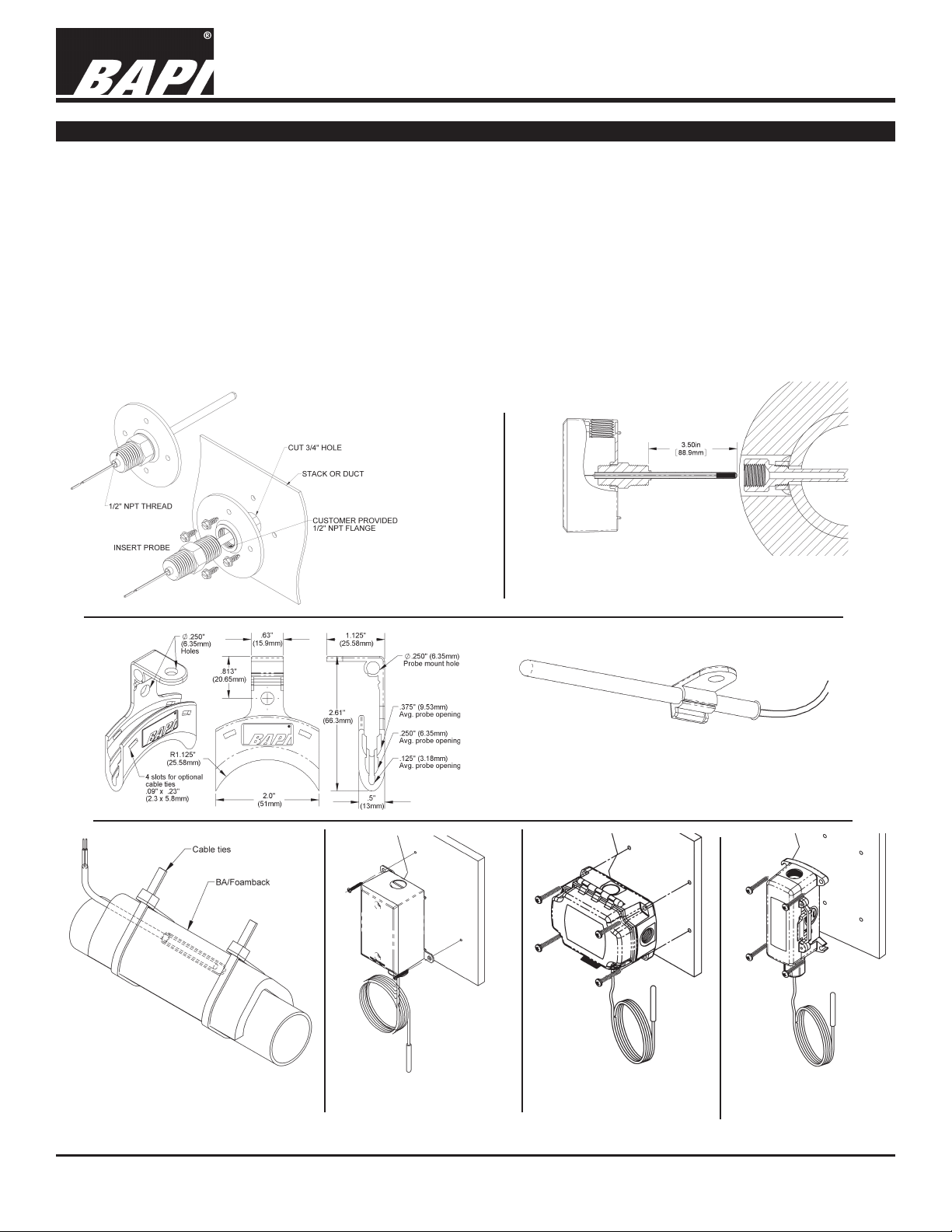
Mounting
Application: Figure 9 shows a typical four-inch thermowell and four-inch immersion probe installed into an eight inch pipe. In a
properly insulated pipe with liquid or steam, the temperature is essentially the same across the entire cross section of the pipe. Usually
thermowells are sized to extend to the center of the pipe; however, shorter thermowells will give proper temperature readings if properly
insulated. The shorter thermowells are used in pipes with high ow velocities. See Application notes “Thermowells Explained” on our
website at www.bapihvac.com
Thermowell Installer: Typically a Pipe Fitter drills a ¾-inch hole into the pipe where the thermowell is needed. A customer provided
tting, called a Threadolet or Weldolet, is welded to the pipe over the hole. The Threadolet has a ½” NPT thread in the center. Thread
sealant such as Teon tape or pipe dope is applied to the ½” NPT threads of the thermowell. The thermowell is then inserted into the
Threadolet and tightened. Estimates on insertion depths can be seen in our Application note “Thermowells Explained” on our website
at www.bapihvac.com
Sensor Installation: Insert the immersion sensor into the well with the stainless steel screw tting into the opening on the well. Hand
tighten the immersion sensor snugly without too much torque. Make sure that the tip of the immersion sensor is inserted as close
to the well bottom as possible. The well is close tting to the sensor and will offer an accurate reading without the need for thermal
compound.
rev. 07/07/16
Fig. 13: Extreme Temp Remote Sensor
in a strap-on application
Fig. 10: Extreme Temp
Probe with ange mount
Fig. 14:
Extreme
Temp Remote
Sensor with
Weatherproof
(WP)
Enclosure
Fig. 11: Extreme Temp Immersion with
Weatherproof Enclosure
Fig. 12: Remote Sensor mounting using the scored break off
of the Flexible Probe Bracket (FPB) which is shown at left.
Fig. 15: Extreme Temp
Remote Sensor with
BAPI-Box (BB)
Fig. 16: Remote Sensor
with BAPI-Box 2 (BB2)
Specications subject to change without notice.
2 of 4
Page 3

Extreme Temperature RTD Sensors
BA/1x[1,2,3] Temperature Sensor
Installation & Operating Instructions
8612_ins_RTD_EXTRM
Mounting continued....
Fig. 18: Extreme
Fig. 17: Extreme Temp
Remote Sensor with
BAPI-Box 4 (BB4)
Enclosure
Temp Remote
Sensor with
Weather Tight (EU)
Enclosure
Fig. 19: Immersion Thermowell
Wiring & Termination
BAPI recommends using twisted pair of at least 22AWG and sealant lled connectors for all wire connections. Larger
gauge wire may be required for long runs. All wiring must comply with the National Electric Code (NEC) and local codes.
Do NOT run this device’s wiring in the same conduit as high or low voltage AC power wiring.
BAPI’s tests show that inaccurate signal levels are possible when AC power wiring is present in the same conduit as the
sensor wires.
rev. 07/07/16
To Controller
Analog Input (AI)
(No Polarity)
Thermistor
or RTD
Sensor
Fig. 20: 2 Wire Lead Wire Termination for Thermistor or RTD
To Controller
Analog Input (AI)
(No Polarity)
Fig. 21: 3 Wire Lead Wire Termination for RTD
Fig. 22: Terminal Strip (-TS) Option for 2 Wire Sensors
Termination
Specications subject to change without notice.
Fig. 23: Terminal Strip (-TS) Option for 3 Wire
Sensors Termination
3 of 4
Page 4

8612_ins_RTD_EXTRM
Diagnostics
Extreme Temperature RTD Sensors
BA/1x[1,2,3] Temperature Sensor
Installation & Operating Instructions
rev. 07/07/16
Problems:
Controller reports higher or
lower than actual temperature
Possible Solutions:
- Conrm the input is set up correctly in the front end software
- Check wiring for proper termination & continuity. (shorted or open)
- Disconnect wires and measure sensor resistance and verify the “Sensor” output
is correct.
Specications
S
ensor Passive resistance
RTD PTC, 2 or 3 wire
RTD Resistance Temperature Device
Platinum (Pt) 1KΩ @0ºC, 385 curve,
Pt Accuracy (std) 0.12% @Ref, or ±0.55ºF, (±0.3ºC)
Pt Stability ±0.25ºF, (±0.14ºC)
Pt Self Heating 0.4 ºC/mW @0ºC
RTD Probe range
1KΩ [1] -328 to 32ºF, (-200 to 0ºC)
1KΩ [2] 77 to 500ºF, (25 to 260ºC)
1KΩ [3] 77 to 1,112ºF, (25 to 600ºC)
Sensitivity Approximate @ 32ºF (0ºC)
RTD (Pt) 3.85Ω/ºC for 1KΩ RTD
0.385Ω/ºC for 100Ω RTD
Lead wire 22awg stranded
Wire Insulation Plenum rated
1KΩ[1] PTFE, -328 to 32ºF, (-200 to 0ºC)
1KΩ[2] PTFE, 77 to 500ºF, (25 to 260ºC)
1KΩ[3] Fiberglass, 77 to 1,112ºF, (25 to 600ºC)
Probe Rigid, 304 Stainless Steel, 0.25” OD
Probe Length
Probe 2”, 4”, 8” or custom per order
Remote Sensor 2” w/ customer cable length
Mounting
Probe ½” NPT Double Threaded
Remote Sensor Probe with or without enclosure
Enclosure Types
Note: The double threaded immersion probe is only
available with the Weatherproof (-WP) box due to the very
high or very low temperature RTD capabilities.
Weatherproof -WP, w/ two ½” FNPT entries, (Bell box)
BAPI-Box
BAPI-Box 2
BAPI-Box 4:
-BB, w/ our ½” NPSM & one ½”
drill-out
-BB2, w/ three ½” NPSM & three ½” drill-outs
-BB4, w/ four ½” drill-outs & one ½” open port
Weather Tight -EU, w/ two ½” knockouts
Enclosure Ratings
Weatherproof -WP, NEMA 3R, IP14
BAPI-Box -BB, NEMA 4X, IP66
BAPI-Box 2 -BB2, NEMA 4X, IP66
BAPI-Box 4 -
BB4, IP10
(IP44 with Knockout Plug in the open port)
Weather Tight -EU, NEMA 4X, IP66
Enclosure Materials
Weatherproof -WP, Cast Aluminum, UV rated
BAPI-Box -BB, Polycarbonate, UL94V-0, UV rated
BAPI-Box 2
-BB2, Polycarbonate, UL94V-0, UV rated
BAPI-Box 4 -BB4, Polycarbonate & Nylon, UL94V-0
Weather Tight -EU, ABS Plastic, UL94V-0
Ambient (Encl.) 0 to 100% RH, Non-condensing
All 3 BAPI-Boxes -40ºF to 185ºF, (-40º to 85ºC)
Weather Tight -40ºF to 185ºF, (-40º to 85ºC)
Weatherproof -100ºF to 1,000ºF, (-73º to 538ºC)
Agency RoHS, CE
PT= DIN43760, IEC Pub 751-1983,
JIS C1604-1989
Specications subject to change without notice.
4 of 4
 Loading...