

Page 1
Submersible Averaging Temperature Sensors (
20906_ins_SubmersibleAvg_Passive
Overview and Identication
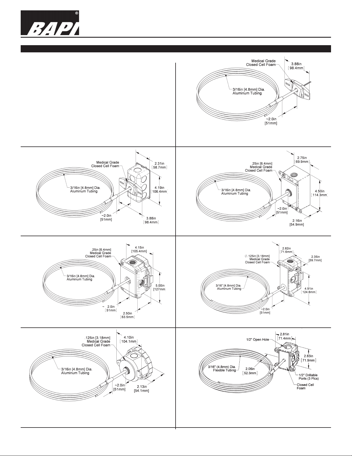
The Submersible Averaging unit is for duct mounting
and temperature measurement of moisture saturated,
stratied air across a duct with a humidier or OSA intake
to give the average mixed air temperature along the
length of the sensor.
The unit may also be used as a sump sensor to average
the water temperature in a water tank. The exible
probe is made of copper and made in different lengths
for a custom duct t. The unit is available in multiple
thermistor’s or RTD’s as shown in the specications.
Enclosure mounting styles come in plastic or metal
for both NEMA 1 and NEMA 4 applications and are all
plenum rated.
BA/#SA)
Installation & Operations
rev. 06/29/15
Fig 1: Duct Unit with No Box (NB)
Fig 2: Duct Unit with J-Box (Standard)
Fig 4: BAPI-Box (BB) Duct Unit
Fig 3: WeatherProof (WP) Duct Unit
Fig 5: BAPI-Box 2 (BB2) Duct
Fig 6: Weather Tight Enclosure (EU) Duct Unit
Fig 7: BAPI-Box 4 (BB4) Duct Unit
(A Pierceable Knockout Plug is available from BAPI
for the open port in the BB4. Part #BA/PKP-100)
Specications subject to change without notice.
1 of 4
Page 2
Submersible Averaging Temperature Sensors (
20906_ins_SubmersibleAvg_Passive
Mounting
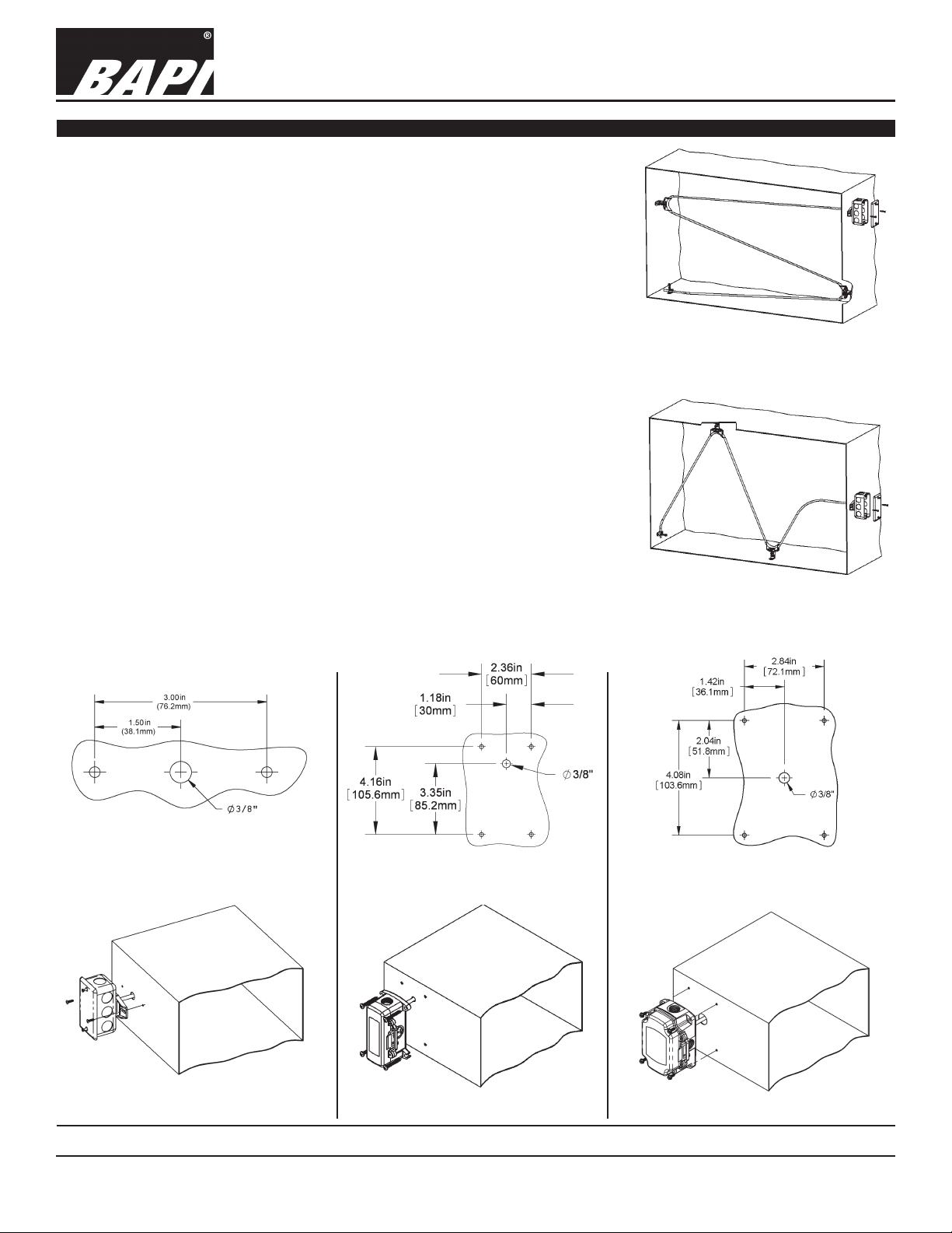
1. Place the sensor in the middle or top of the duct as shown in Fig 8 or Fig 9
so the exible probe can enter the duct in a convenient place. Drill the probe
and mounting holes as depicted for the enclosure being used. (No Box,
Handy Box, BB, BB2, WP, EU, BB4).
2. Insert the probe by unrolling the sensor into the duct carefully to avoid kink-
ing the sensor. Serpentine the duct with the sensor at least twice across the
stratied air in the duct to achieve the best average temperature reading. At
the sensor reversing points a turning bracket (BA/FPB) should be used to
support the sensor and to avoid kinking the sensor.
BA/#SA)
Installation & Operations
rev. 06/29/15
3. Mount the enclosure to the duct using BAPI recommended #8 screws
through a minimum of two opposing mounting tabs provided. Weatherproof
(WP) enclosures will require assembly of the mounting tabs on opposite corners. A 1/8 inch pilot screw hole in the duct makes mounting easier through
the mounting tabs. Use the enclosure tabs to mark the pilot hole locations.
4. Snug up the sensors so that the foam backing is depressed to prevent air
leakage but do not over-tighten or strip the screw threads.
Note 1: Be sure not to drill into the weatherproof enclosures (BB, BB2, WP, EU,
EUO) which will violate the NEMA and/or the IP rating.
Note 2: Be sure to use caulk or Teon tape for your conduit entries to maintain
the appropriate NEMA or IP rating for your application.
Note 3: Conduit entry for outdoor or wet applications should be from the bottom
of the enclosure.
Fig 8: Flexible Sensor Horizontal Mount
(Best for Vertical Stratication)
Fig 9: Flexible Sensor Vertical Mount
(Best for Horizontal Stratication)
Fig 10: Junction Box or No Box (NB)
Mounting Holes and installation
Fig 11: BAPI-Box 2 (BB2) Mounting
Holes and installation.
Specications subject to change without notice.
Fig 12: BAPI-Box (BB) Enclosure Mount-
ing and installation Holes (Rotate
90° for Horizontal Mounting)
2 of 4
Page 3
20906_ins_SubmersibleAvg_Passive
Mounting continued...
Submersible Averaging Temperature Sensors (
Installation & Operations
BA/#SA)
rev. 06/29/15
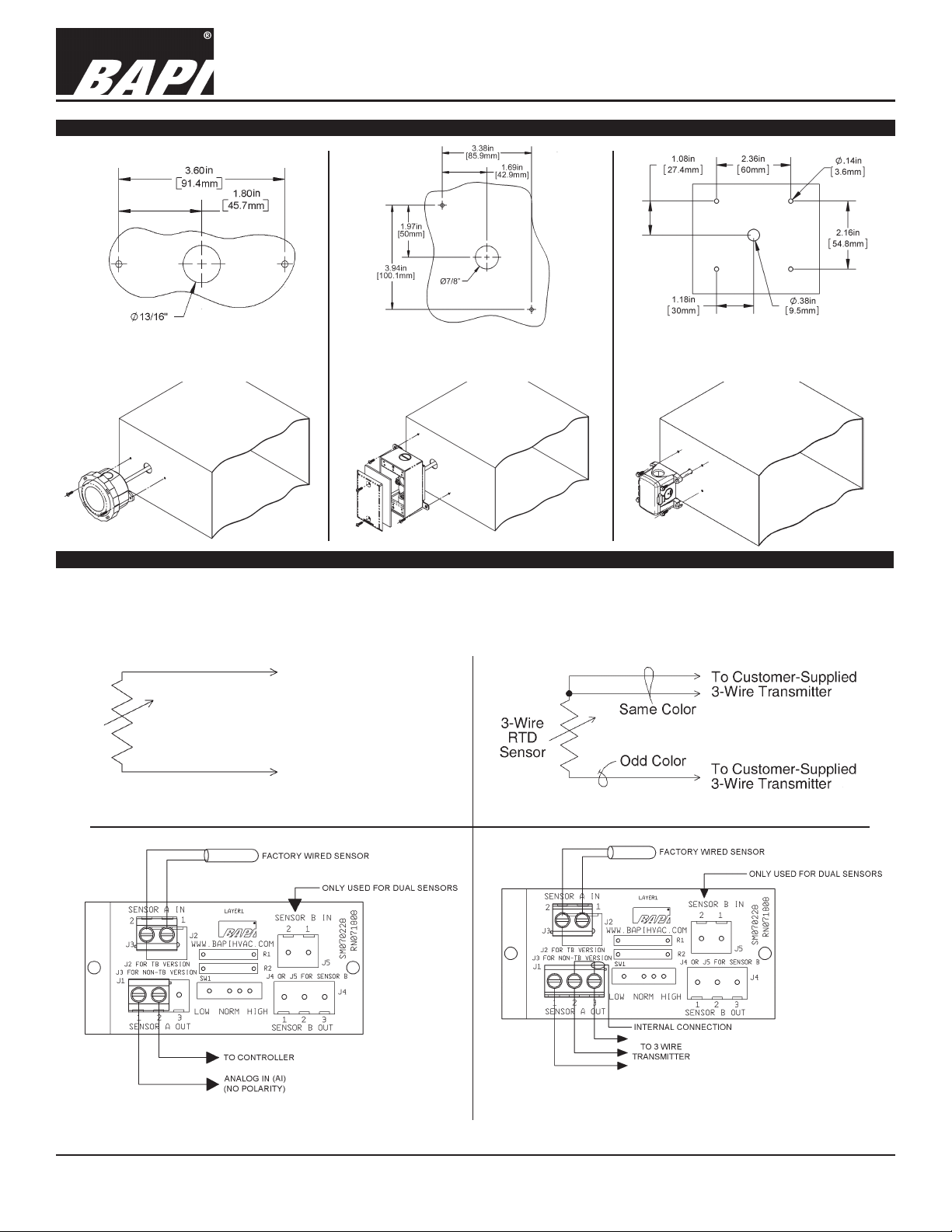
Fig 13: Weather Tight
Mounting Holes and Installation
EU or EUO Encl.
Fig 14:
Weatherproof Box WB Mounting
Holes
and Installation
Fig 15: BAPI-Box 4 (BB4) Enclosure
Mounting Holes and Installation
Wiring & Termination
BAPI recommends using twisted pair of at least 22AWG and sealant lled connectors for all wire connections. Larger gauge wire may
be required for long runs. All wiring must comply with the National Electric Code (NEC) and local codes. Do NOT run this device’s wiring
in the same conduit as high or low voltage AC power wiring.
BAPI’s tests show that inaccurate signal levels are possible when AC power wiring is present in the same conduit as the sensor wires.
To Controller
Analog Input (AI)
Thermistor
(No Polarity)
or RTD
Sensor
To Controller
Analog Input (AI)
(No Polarity)
Fig. 16: 2 Wire Lead Wire Termination for Thermistor or RTD
Fig. 17: 3 Wire Lead Wire Termination for RTD
Fig. 18:
Terminal Strip (-TS)
Option for 2 Wire
Sensors Termination
Specications subject to change without notice.
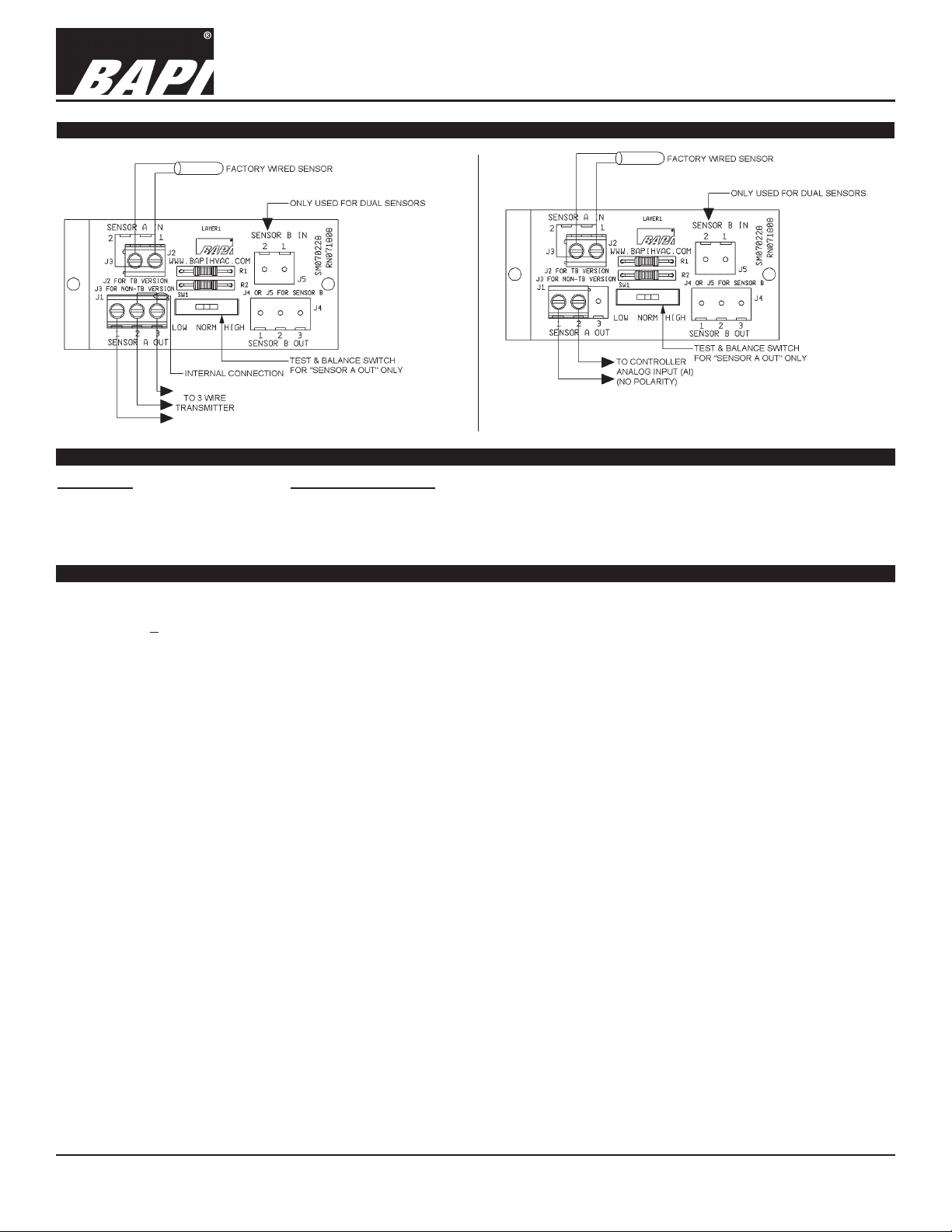
Fig. 19:
Terminal Strip (-TS)
Option for 3 Wire
Sensors Termination
3 of 4
Page 4
20906_ins_SubmersibleAvg_Passive
Wiring & Termination continued...
Submersible Averaging Temperature Sensors (
Installation & Operations
BA/#SA)
rev. 06/29/15
Fig. 20:
Test & Balance (-TB) Option
for 2 Wire Sensors Termination
Diagnostics
Problems:
Controller reports higher or
lower than actual temperature.
Possible Solutions:
- Conrm the input is set up correctly in the front end software
- Check wiring for proper termination & continuity. (shorted or open)
- Disconnect wires and measure sensor resistance and verify the “Sensor” output is correct.
Specications
Sensor Passive
Thermistor 4 sensors in < 24’ probes
9 sensors in > 24’ probes
RTD Continuous sensor, 2 or 3 wire
Thermistor Thermal resistor (NTC)
Temp. Output Resistance per order
Accuracy (std) ±0.36ºF, (±0.2ºC)
Accuracy (Hi) ±0.18ºF, (±0.1ºC), [XP] option
Stability < 0.036ºF/Year, (<0.02ºC/Year)
Heat dissipation 2.7 mW/ºC
Temp. Drift <0.02ºC per year
Probe range -40º to 221ºF (-40º to 105ºC)
RTD Resistance Temp Device (PTC)
Platinum (Pt) 100Ω and 1KΩ @0ºC, 385 curve
Platinum (Pt) 1KΩ @0ºC, 375 curve
Pt Accuracy (std) 0.12% @Ref,
or ±0.55ºF, (±0.3ºC)
Pt Stability ±0.25ºF, (±0.14ºC)
Pt Self Heating 0.4 ºC/mW @0ºC
Pt Probe range -40º to 221ºF, (-40 to 105ºC)
Nickel (Ni) 1000Ω @70ºF, JCI curve
Ni Probe range -40º to 221ºF (-40 to 105ºC)
Sensitivity Approximate
Thermistor Non-linier (Go to bapihvac.com for specs)
RTD (Pt) 3.85Ω/ºC for 1KΩ RTD
0.385Ω/ºC for 100Ω RTD
Nickel (Ni) 2.95Ω/ºF for the JCI RTD
Lead Wire
Probe Flexible Copper Tube, 0.19” OD
Probe Length
Duct Gasket
Mounting Extension tabs (ears), 3/16” holes
Water Seal
at Both Ends
Teon Coated Sensors and Heat Sealed
22awg stranded, etched teon, Plenum rated
2’, 4’ or 8’ per order
1/4” Closed cell foam (impervious to mold)
Specications subject to change without notice.
Fig. 21:
Test & Balance (-TB)
Option for 3 Wire Sensors
Termination
Enclosure Types
J-Box -JB, w/eight ½” knockouts
No Box -NB, intended for open wiring
Weather Proof -WP, w/ two ½” FNPT entries, (Bell box)
BAPI-Box -BB, w/four ½” NPSM & one 1/2” drill-out
BAPI-Box 2 -BB2, w/three ½” NPSM & three 1/2” drill-outs
BAPI-Box 4: -BB4, w/ three ½” drill-outs & one ½” open port
Weather Tight -EU, -EUO, w/two ½” knockouts
Enclosure Ratings
J-Box -JB, NEMA 1
No Box -NB, No rating
Weather Proof -WP, NEMA 3R, IP14
BAPI-Box -BB, NEMA 4X, IP66
BAPI-Box 2 -BB2, NEMA 4X, IP66
BAPI-Box 4: -BB4, IP44 (IP44 with Knockout Plug installed)
Weather Tight -EU, -EUO, NEMA 4X, IP66 (EUO is UV-rated)
Enclosure Materials
J-Box -JB, Galvanized steel, UL94H-B
No Box -NB, Nylon 66, UL94H-B
Weather Proof -WP, Cast Aluminum, UV rated
BAPI-Box -BB, Polycarbonate, UL94V-0, UV rated
BAPI-Box 2 -BB2, Polycarbonate, UL94V-0, UV rated
BAPI-Box 4: -BB4, Polycarbonate & Nylon, UL94V-0
Weather Tight -EU, ABS Plastic, UL94V-0
Weather Tight -EUO, ABS Plastic, UL94V-0, UV rated
Ambient (Encl.)
All BAPI-Boxes -BB, BB2, BB4, -40ºF to 185ºF, (-40º to 85ºC)
Weather Tight -EUO, EU, -40ºF to 185ºF, (-40º to 85ºC)
J-Box & No Box -JB, NB, -40ºF to 212ºF, (-40º to 100ºC)
Weatherproof -WP, -40ºF to 212ºF, (-40º to 100ºC)
Agency RoHS, *CE
JIS C1604-1989
*Passive Thermistors 20KΩ and smaller are CE
0 to 100% RH, Non-condensing
PT=DIN43760, IEC Pub 751-1983,
4 of 4
 Loading...