

Page 1
20911_ins_Duct_Strap_On_Passive
Overview and Identication
Strap Sensors are made for direct pipe mounting and
temperature measurement of water pipe applications.
The Clamp-On units are for mounting before any
insulation is on the pipe and the Spring-Loaded units are
for mounting to pipes with up to 2” of insulation using a
unique spring sensor extension.
Both units are available with multiple thermistor’s or RTD’s
as shown in the specications. Enclosure mounting styles
come in plastic or metal for both NEMA 1 and NEMA 4
applications and are all plenum rated.
Strap-On Temperature Sensors - BA/#-(S,STP)
Installation & Operations
rev. 06/29/15
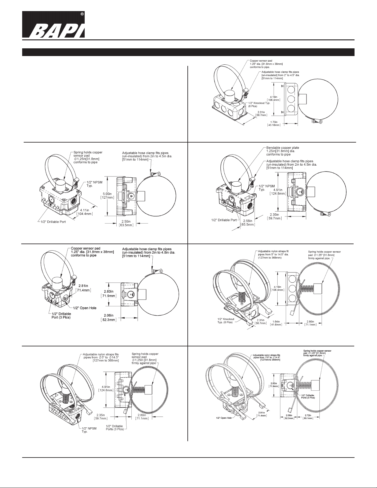
Fig 1: Clamp-On Strap with NEMA 1 J-Box (JB)
Fig 4: Clamp-On Strap with NEMA 1 BAPI-Box 4 (BB4)
(A Pierceable Knockout Plug is available from BAPI for the
open port in the BB4. Part #BA/PKP-100)
Fig 3: Clamp-On Strap with w/ NEMA 4 BAPI-Box 2 (BB2)Fig 2: Clamp-On Strap with w/ NEMA 4 BAPI-Box (BB)
Fig 5: Spring-Loaded Strap w/ NEMA 1 J-Box (JB)
Fig 6: Spring-Loaded Strap w/ NEMA 4 BAPI-Box 2 (BB2)
Specications subject to change without notice.
Fig 7: Spring-Loaded Strap w/ NEMA 1 BAPI-Box 4 (BB4)
(A Pierceable Knockout Plug is available from BAPI for the
open port in the BB4. Part #BA/PKP-100)
1 of 4
Page 2
20911_ins_Duct_Strap_On_Passive
Mounting
Strap-On Temperature Sensors - BA/#-(S,STP)
Installation & Operations
rev. 06/29/15
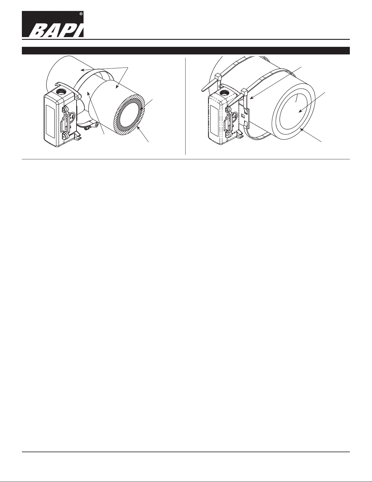
2 Inch Insulation
Cleaned off To
Bare Pipe
Fig 8: Typical Clamp-On (-S) Installation
The Pipe
Pipe
Insulation
Fig 9: Typical Spring-Loaded (-STP) Installation
1.5 Inch Hole In
The Insulation
Pipe
Insulation
Application: This sensor technique is for reading the uid temperature in a pipe by reading the temperature of the pipe.
Properly installed strap sensors with insulation around the local strap-on sight will offer a very accurate temperature of the
water inside the pipe to within .5 °F or better of the inside pipe water temperature.
Clamp-On Unit Installation: BA/#-S
1. Fig 8 shows a typical installation for pipes from 2” to 4.5”. Stripping away insulation is OK.
2. Larger pipes can be accommodated by adding another, customer supplied, stainless steel hose clamp extending the
possible pipe diameter.
3. If there is insulation, clean away a section of the pipe insulation a minimum of 2” all around the pipe. The copper sensor pad and SS strap must be in direct contact with the metal or plastic pipe. Note: Nothing should be between the
copper plate sensor and the bare pipe.
4. Tighten the strap-so that the sensor does not rotate around the pipe and so that the foam is compressed not more than
50% allowing the copper sensor plate to form (bend) to the pipe curvature for maximum temperature conduction. BAPI
recommends pre-forming the copper plate by bending it around the pipe with your ngers.
5. After the strap-on sensor is securely mounted, add insulation a minimum of 1” thick and a minimum of 4 pipe diameters
on each side of the copper sensor pad. (Example: A 2” pipe should have 8” of insulation on each side of the sensor).
Only cover the sensor box to the top of the metal cover plate or to the BB door hinge so termination and servicing can
be completed.
6. Terminate per the following Wiring and Termination Section.
Spring Loaded Unit Installation: BA/#-STP
1. Fig 9 shows a typical installation for insulated pipes from 5” to 14”. Insulation thickness accommodated is 0.5” to 2.5”.
2. Larger pipes can be accommodated by adding another, customer supplied, tie rap strap extending the possible pipe
diameter.
3. Make a 1.5 inch diameter hole in the insulation where the sensor is to be placed and clean the pipe from debris. Extend the spring so the copper sensor pad is in direct contact with the metal or plastic pipe. Note: No debris should be
between the copper plate sensor and the bare pipe. The spring can retract to a minimum insulation thickness of ~.5”
compressed to ~2.5” extended.
4. Position the box and sensor over the hole.
5. Tighten the strap so that the sensor spring is compressed no more than 50% allowing the copper sensor plate to form
(bend) to the pipe curvature for maximum temperature conduction. BAPI recommends pre-forming the copper plate by
bending it around the pipe with your ngers. Extend the spring further by turning it clockwise if the copper sensor plate
contact is questionable. The copper sensor plate must be in direct contact with the pipe.
6. After the strap on sensor is securely mounted, add insulation back in (backll) around the spring extension, using the
removed insulation, so that no heat or cold from the pipe can escape.
7. If more insulation is desired, only cover the sensor box to the top of the metal cover plate or to the BB door hinge so
termination and servicing can be completed.
8. Terminate per the following Wiring and Termination Section.
Specications subject to change without notice.
2 of 4
Page 3

Strap-On Temperature Sensors - BA/#-(S,STP)
Installation & Operations
20911_ins_Duct_Strap_On_Passive
Wiring & Termination
BAPI recommends using twisted pair of at least 22AWG and sealant lled connectors for all wire connections. Larger gauge wire may
be required for long runs. All wiring must comply with the National Electric Code (NEC) and local codes. Do NOT run this device’s wiring
in the same conduit as high or low voltage AC power wiring.
BAPI’s tests show that inaccurate signal levels are possible when AC power wiring is present in the same conduit as the sensor wires.
To Controller
Analog Input (AI)
Thermistor
(No Polarity)
or RTD
Sensor
To Controller
Analog Input (AI)
(No Polarity)
Fig. 10: 2 Wire Lead Wire Termination for Thermistor or RTD Fig. 11: 3 Wire Lead Wire Termination for RTD
rev. 06/29/15
Fig. 12: Terminal Strip (-TS) Option for 2 Wire Sensors Termination
Specications subject to change without notice.
Fig. 13: Terminal Strip (-TS) Option for 3 Wire Sensors Termination
Fig. 15: Test & Balance (-TB) Option for 3 Wire Sensors TerminationFig. 14: Test & Balance (-TB) Option for 2 Wire Sensors Termination
3 of 4
Page 4

20911_ins_Duct_Strap_On_Passive
Diagnostics
Possible Problem:
Controller reports higher or
lower than actual temperature
Specications
Strap-On Temperature Sensors - BA/#-(S,STP)
Installation & Operations
rev. 06/29/15
Possible Solutions:
- Conrm the input is set up correctly in the front end software
- Check wiring for proper termination & continuity. (shorted or open)
- Disconnect wires and measure sensor resistance and verify the
“Sensor” output is correct.
Sensor Passive
Thermistor NTC, 2 wire
RTD PTC, 2 or 3 wire
Thermistor Thermal resistor
Temp. Output Resistance
Accuracy (Std) ±0.36ºF, (±0.2ºC)
Accuracy (High) ±0.18ºF, (±0.1ºC), [XP] option
Stability < 0.036ºF/Year, (<0.02ºC/Year)
Heat dissipation 2.7 mW/ºC
Temp. Drift <0.02ºC per year
Probe range -40º to 221ºF (-40º to 105ºC)
RTD Resistance Temperature Device
Platinum (Pt) 100Ω or 1KΩ @0ºC, 385 curve,
Platinum (Pt) 1KΩ @0ºC, 375 curve
Pt Accuracy (Std) 0.12% @Ref, or ±0.55ºF, (±0.3ºC)
Pt Accuracy (High) 0.06% @Ref, or ±0.277ºF
(±0.15ºC), [A]option
Pt Stability ±0.25ºF, (±0.14ºC)
Pt Self Heating 0.4 ºC/mW @0ºC
Pt Probe range -40º to 221ºF, (-40 to 105ºC)
Nickel (Ni) 1000Ω @70ºF, JCI curve
Ni Probe range -40º to 221ºF (-40 to 105ºC)
Sensitivity Approximate @ 32ºF (0ºC)
Thermistor Non-linier
See bapihvac.com “Sensor Specs”
1KΩ RTD (Pt) 3.85Ω/ºC
100Ω RTD (Pt) 0.385Ω/ºC
Nickel (Ni) 2.95Ω/ºF for the JCI RTD
Lead wire 22awg stranded
Wire Insulation
Etched Teon, Plenum rated
Probe Copper sensor plate, 24 AWG,
1.25” diameter
Mounting
Clamp-On -S, ½” Stainless steel worm gear hose
clamp
Strap-On -STP, 48” Nylon tie strap, 1/2” wide
Enclosure Types: (Part number designator in bold)
J-Box: -JB, w/ eight ½” knock-outs
BAPI-Box: -BB, w/ four ½” NPSM & one ½” drill-out
BAPI-Box 2:
BAPI-Box 4:
-BB2, w/ three ½” NPSM & three ½” drill-outs
-BB4, w/ three ½” drill-outs & one ½” open port
Enclosure Ratings: (Part number designator in bold)
J-Box: -JB, NEMA 1
BAPI-Box: -BB, NEMA 4, IP66, UV Rated
BAPI-Box 2: -BB2, NEMA 4, IP66, UV Rated
BAPI-Box 4: -BB4, IP10 (with spring installed)
(IP44 without spring and with Knockout
Plug installed in the open port)
Enclosure Material: (Part number designator in bold)
J-Box: -JB, Galvanized steel, UL94H-B
BAPI-Box: -BB, Polycarbonate, UL94V-0, UV rated
BAPI-Box 2: -BB2, Polycarbonate, UL94V-0, UV rated
BAPI-Box 4: -BB4, Polycarbonate & Nylon, UL94V-0
Ambient (Enclosure): 0 to 100% RH, Non-condensing
J-Box: -JB, -40ºF to 212ºF, (-40º to 100ºC)
BAPI-Box: -BB, -40ºF to 185ºF, (-40 to 85ºC)
BAPI-Box 2: -BB2, -40ºF to 185ºF, (-40 to 85ºC)
BAPI-Box 4: -BB4, -40ºF to 185ºF, (-40 to 85ºC)
Agency: RoHS, *CE
PT= DIN43760, IEC Pub 751-1983,
JIS C1604-1989
*Passive Thermistors 20KΩ and smaller are
CE Compliant
Specications subject to change without notice.
4 of 4
 Loading...