

Page 1
Strap-On Sensors Transmitters
BA/Txx-(S, STP) Temperature Sensor
Installation & Operating Instructions
20922_ins_Strap on_Active
Overview
The BA/Txx#-(S, STP) Strap on Sensors are made for direct pipe mounting and temperature measurement of water pipe
applications. The BA/Txx#-S is for mounting before any insulation is on the pipe and the BA/Txx#-STP is for mounting to
pipes with up to 2” of insulation using a unique spring sensor extension. The 4 to 20mA transmitter can be ordered with
100Ω (385), 1KΩ (385) RTDs or 10KΩ type 2 thermistor sensor. A 0 to 5VDC or 0 to 10VDC transmitter is also available
with the 10KΩ type 2 thermistor sensor. Special high accuracy RTD matched transmitters (M) are available which match
the sensor to the transmitter for improved accuracy. Enclosure mounting styles come in plastic or metal for both NEMA 1
and NEMA 4 applications and are all plenum rated.
Identication
6
rev.04/18/13
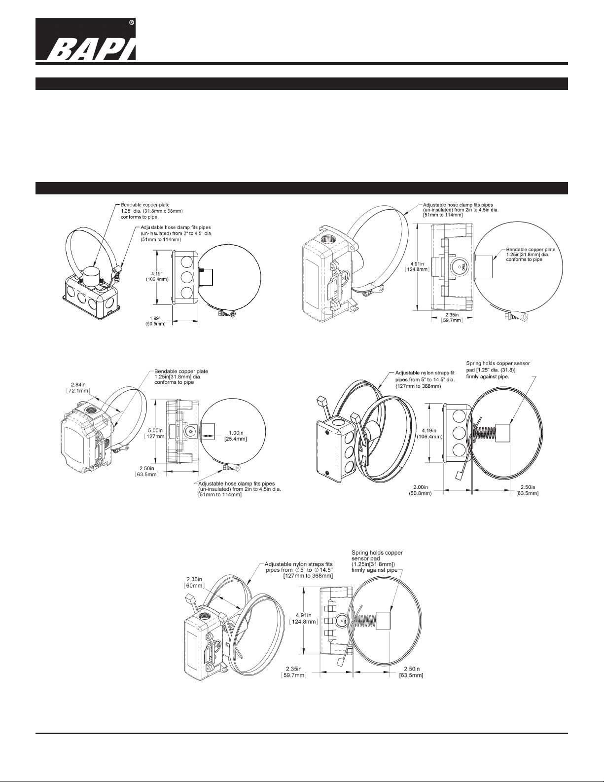
Fig. 1: Clamp-On Strap Unit with Junction Box (Standard)
Fig. 3: Clamp-On Strap Unit in BAPI-Box (BB) Enclosure
Fig. 2: Clamp-On Strap Unit in BAPI-Box 2 (BB2) Enclosure
Fig. 4: Spring Loaded Strap Unit in a Junction Box (Standard)
Fig. 5: Spring Loaded Strap Unit in a BAPI-Box 2 (BB2) Enclosure
Specications subject to change without notice.
1 of 4
Page 2
20922_ins_Strap on_Active
Strap Mount Application
Strap-On Sensors Transmitters
BA/Txx-(S, STP) Temperature Sensor
Installation & Operating Instructions
rev.04/18/13
Application: This sensor technique is for reading the uid temperature in
a pipe by reading the temperature of the pipe. Properly installed Strap-On
sensors with insulation around the local strap-on sight will offer a very accu-
2 inches of
insulation removed
to let the sensor
contact bare pipe
rate temperature of the water inside the pipe to within .5 °F or better of the
inside pipe water temperature.
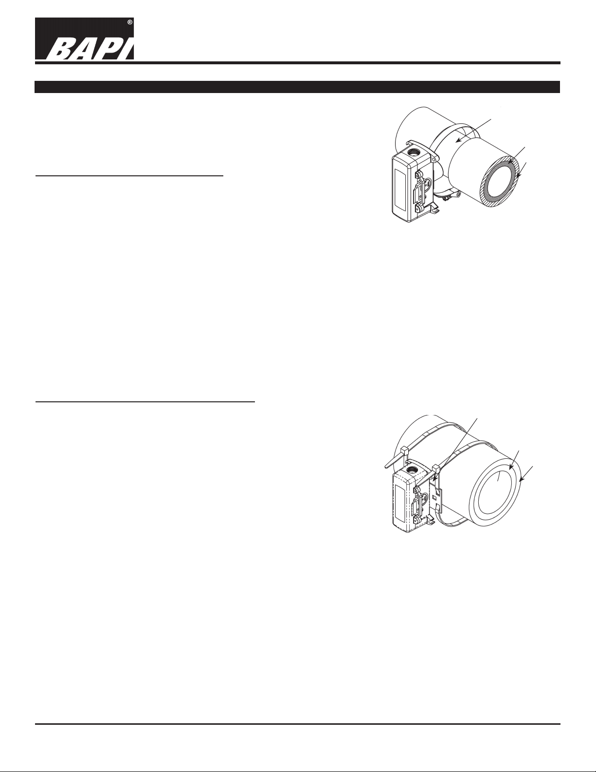
Clamp-On Strap Unit Installation: BA/#-S
1. Figure 6 show a typical direct pipe installation for pipes from 2” to
4.5”. Stripping away insulation is OK.
2. Larger pipes can be accommodated by adding another, customer
supplied, stainless steel hose clamp extending the possible pipe
diameter.
3. If there is insulation, clean away a section of the pipe insulation a
minimum of 2” all around the pipe. The copper sensor pad and SS
Fig. 6: Clamp-On Strap Unit Mounting
(BAPI-Box 2 Enclosure shown
but mounting is similar for all
BAPI-Boxes.)
strap must be in direct contact with the metal or plastic pipe. Note:
Nothing should be between the copper plate sensor and the bare pipe.
4. Tighten the strap-so that the sensor does not rotate around the pipe and so that the foam is compressed not more
than 50% allowing the copper sensor plate to form (bend) to the pipe curvature for maximum temperature conduction. BAPI recommends pre-forming the copper plate by bending it around the pipe with your ngers.
5. After the strap-on sensor is securely mounted, add insulation a minimum of 1” thick and a minimum of 4 pipe diameters on each side of the copper sensor pad. (EXPL. A 2” pipe should have 8” of insulation on each side of the
sensor). Only cover the sensor box to the top of the metal cover plate or to the BB door hinge so termination and
servicing can be completed.
6. Terminate per the following Wiring and Termination Section.
Pipe
Insulation
String-Loaded Strap Unit Installation: BA/#-STP
1. Figure 7 shows a typical direct pipe installation for insulated pipes
from 5” to 14”. Insulation thickness accommodated is 0.5” to 2.5”.
2. Larger pipes can be accommodated by adding another, customer
1.5 inch hole in the
Insulation to let the
spring-loaded sensor
contact bare pipe
supplied, tie rap strap extending the possible pipe diameter.
3. Make a 1.5 inch diameter hole in the insulation where the sensor
is to be placed and clean the pipe from debris. Extend the spring
so the copper sensor pad is in direct contact with the metal or
plastic pipe. Note: No debris should be between the copper plate
sensor and the bare pipe. The spring can retract to a minimum
insulation thickness of ~.5” compressed to ~2.5” extended.
4. Position the box and sensor over the hole.
5. Tighten the strap so that the sensor spring is compressed no
more than 50% allowing the copper sensor plate to form (bend)
to the pipe curvature for maximum temperature conduction. BAPI
Fig. 7: Spring Loaded Strap Unit Mounting
(BAPI-Box 2 Enclosure shown but
mounting is similar for all BAPI-Boxes.)
recommends pre-forming the copper plate by bending it around
the pipe with your ngers. Extend the spring further by turning it
clockwise if the copper sensor plate contact is questionable. The copper sensor plate must be in direct contact
with the pipe.
6. After the strap on sensor is securely mounted, add insulation back in (backll) around the spring extension, using
the removed insulation, so that no heat or cold from the pipe can escape.
7. If more insulation is desired, only cover the sensor box to the top of the metal cover plate or to the BB door hinge
so termination and servicing can be completed.
8. Terminate per the following Wiring and Termination Section.
Pipe
Insulation
Specications subject to change without notice.
2 of 4
Page 3

Strap-On Sensors Transmitters
BA/Txx-(S, STP) Temperature Sensor
Installation & Operating Instructions
20922_ins_Strap on_Active
Wiring & Termination
BAPI recommends using twisted pair of at least 22AWG and sealant lled connectors for all wire connections. Larger gauge wire
may be required for long runs. All wiring must comply with the National Electric Code (NEC) and local codes. Do NOT run this
device’s wiring in the same conduit as high or low voltage AC power wiring. BAPI’s tests show that inaccurate signal levels are
possible when AC power wiring is present in the same conduit as the sensor wires.
rev.04/18/13
Fig. 8: Typical RTD 4 to 20 mA Transmitter with Flying Leads
Fig. 10: Typical Thermistor 4 to 20mA Transmitter
Fig. 9: Typical RTD 4 to 20mA Transmitter with Terminals
Fig. 11: Typical Thermistor Voltage Transmitter
Diagnostics
Possible Problems: Possible Solutions:
•
Unit will not operate. - Measure the power supply voltage by placing a voltmeter across the transmitter’s (+) and
- Check if the RTD wires are physically open or shorted together and are terminated to the
- Measure the physical temperature at the temperature sensor’s location using an accurate
• The reading is incorrect in the controller.
- For a 4-20mA current transmitter measure the transmitter current by placing an ammeter
Voltage Temperature Equation
T = TLow + (V x TSpan)
VSpan
T = Temperature at sensor
TLow = Low temperature of span
THigh = High temperature of span
TSpan = THigh - TLow
VLow = Low transmitter voltage
usually=(0, 1 or 2v)
VHigh = High transmitter voltage
usually=(5 or 10v)
VSpan = VHigh - VLow
V = Signal reading in volts
(-) terminal. Make sure that it matches the drawings above and power requirements in the
specications.
transmitter.
temperature standard. Disconnect the temperature sensor wires and measure the
temperature sensor’s resistance with an ohmmeter. Compare the temperature sensor’s
resistance to the appropriate temperature sensor table on the BAPI web site.
- Determine if the input is set up correctly in the controllers and BAS software.
in series with the controller input. The current should read according to the “4-20mA
Temperature Equation” shown below.
- For a voltage transmitter, measure the signal with a volt meter (Orange or Orange/Black to
Black). The signal should read according to the “Voltage Temperature Equation” shown below.
4-20mA Temperature Equation
T = TLow + (A -4) x (TSpan)
16
T = Temperature at sensor
TLow = Low temperature of span
THigh = High temperature of span
TSpan = THigh - TLow
A = Signal reading in mA
Specications subject to change without notice.
3 of 4
Page 4

20922_ins_Strap on_Active
Specications
Strap-On Sensors Transmitters
BA/Txx-(S, STP) Temperature Sensor
Installation & Operating Instructions
rev.04/18/13
RTD Transmitter
Power Required: 7 to 40VDC
Transmitter Output: 4 to 20mA, 850Ω@24VDC
Output Wiring: 2 wire loop
Output Limits: <1mA (short), <22.35mA (open)
Span:
Zero:
Min. 30ºF (17ºC), Max 1000ºF, (555ºC)
Min. -148°F (-100°C), Max 900ºF (482ºC)
Zero & Span Adjust: 10% of span
Accuracy: ±0.065% of span
Linearity: ±0.125% of span
Power Output Shift: ±0.009% of span
RTD Sensor: 2 wire Platinum (Pt), 385 curve
Transmitter Ambient -4 to 158ºF(-20 to 70ºC)
0 to 95% RH, Non-condensing
Thermistor Transmitter
Supply Voltage:
10 to 35 VDC (0 to 5 VDC or 4 to 20 mA Outputs)
15 to 35 VDC (0 to 10 VDC Output)
12 to 24 VAC (0 to 5 VDC Outputs)
15 to 24 VAC (0 to 10 VDC Output)
Transmitter Output: 4 to 20mA, 700Ω@24VDC
0 to 5 & 0 to 10VDC, 10KΩ min
Output Wiring: 2 & 3 wire (See wiring detail on pg. 3)
Transmitter Limits: -40 to 185ºF, (-40 to 85ºC)
Accuracy: ±1.015ºC, from (0 to 65ºC)
Linearity: ±0.065ºC, from (0 to 65ºC)
Resolution: Span/1024
Thermistor Sensor: 10K-2 Thermistor, 10KΩ @77ºF
Transmitter Ambient: 32 to 158ºF, (0º to 70ºC)
0 to 95% RH, Noncondensing
Thermistor:
10K-2,Thermal Resistor (Bare Sensor)
Accuracy (Std): ±0.36ºF, (±0.2ºC)
Accuracy (High): ±0.18ºF, (±0.1ºC), [XP] option
Stability: < 0.036ºF/Year, (<0.02ºC/Year)
Heat Dissipation: 2.7 mW/ºC
Probe Range: -40º to 221ºF (-40º to 105ºC)
Wire Colors:
Standard: Yellow/Yellow (no polarity)
High Acc. [XP]: Yellow/Yellow (no polarity)
RTD:
Resistance Temp Device (Bare Sensor)
Platinum (Pt): 100Ω and 1KΩ @0ºC, 385 curve,
Pt Accuracy (Std): 0.12% @Ref, or ±0.55ºF, (±0.3ºC)
Pt Accuracy (High): 0.06% @Ref, or ±0.277ºF,
(±0.15ºC), [A]option
Pt Stability: ±0.25ºF, (±0.14ºC)
Pt Self Heating: 0.4 ºC/mW @0ºC
Pt Probe Range: -40º to 221ºF, (-40 to 105ºC)
Wire Colors:
General color code (other colors possible)
1KΩ, Class B Orange/Orange (no polarity)
1KΩ, Class A Orange/White (no polarity)
100Ω, Class B Red/Red (no polarity)
100Ω, Class A Red/Red-w/black stripe (no polarity)
Sensitivity: Approximate @ 32ºF (0ºC)
Thermistor: Non-linier (See www.bapihvac.com,
click “Sensor Specs”)
RTD (Pt): 3.85Ω/ºC for 1KΩ RTD
0.385Ω/ºC for 100Ω RTD
Lead Wire: 22awg stranded
Insulation: Etched Teon, Plenum rated
Probe: Copper Sensor Plate, 24awg, 1.25” dia.
Mounting:
-S, ½” Stainless steel worm gear hose clamp
-STP, 48” Nylon tie strap, ½” wide
Enclosure Types: (Part number designator in bold)
2”x4” J-Box: Standard w/ eight ½” knock-outs
BAPI-Box: -BB, w/ four ½” NPSM & one ½” drill-out
BAPI-Box 2:
-BB2, w/ three ½” NPSM & three ½” drill-outs
Enclosure Ratings: (Part number designator in bold)
2x4 J-Box: Standard, NEMA 1
BAPI-Box: -BB, NEMA 4, IP66, UV Rated
BAPI-Box 2: -BB2, NEMA 4, IP66, UV Rated
Enclosure Material: (Part number designator in bold)
2x4 J-Box: Galvanized steel, UL94H-B
BAPI-Box: -BB, Polycarbonate, UL94V-0, UV rated
BAPI-Box 2:
-BB2, Polycarbonate, UL94V-0, UV rated
Ambient (Enclosure): 0 to 100% RH, Non-condensing
BB, BB2: -40ºF to 185ºF, (-40º to 85ºC)
J-Box, WP: -40ºF to 212ºF, (-40º to 100ºC)
Agency: RoHS
PT= DIN43760, IEC Pub 751-1983,
JIS C1604-1989
Specications subject to change without notice.
4 of 4
 Loading...