

Page 1
SD2 - Status Display, Dual 7-Segment Display
Installation and Operation Instructions
35827_ins_SD2.pdf
Overview
The SD2 is an ETA module that is used to indicate a program error code
which requires a manual reset. The module includes a manual reset switch
that can be pressed to route a reset signal to a controller.
The polarity of the reset switch can be set to Normally Open (NO) or
Normally Closed (NC) operation via the jumper on J2. When the reset
switch is pressed, Terminals #3 and #4 of J1 are either connected or
disconnected. Two 7-segment displays are available at the edge of the
module, denoting where the input signal is within the range.
The SD module receives an input signal from a controller, and then
displays a number from 0 to 10 up to 0 to 50, depending on the jumper
position of J3. It can accept a current input of either 0 to 20mA or 4 to
20mA or a voltage input of 0 to 10V or 2 to 10V.
The unit is typically mounted in a BP2, BP4, BP8 or BP4V Backplane
with power provided by the Backplane; however, the unit can be powered
directly with an alternate DC supply. The green LED indicates that power is
available to the module.
Mounting
rev. 11/18/15
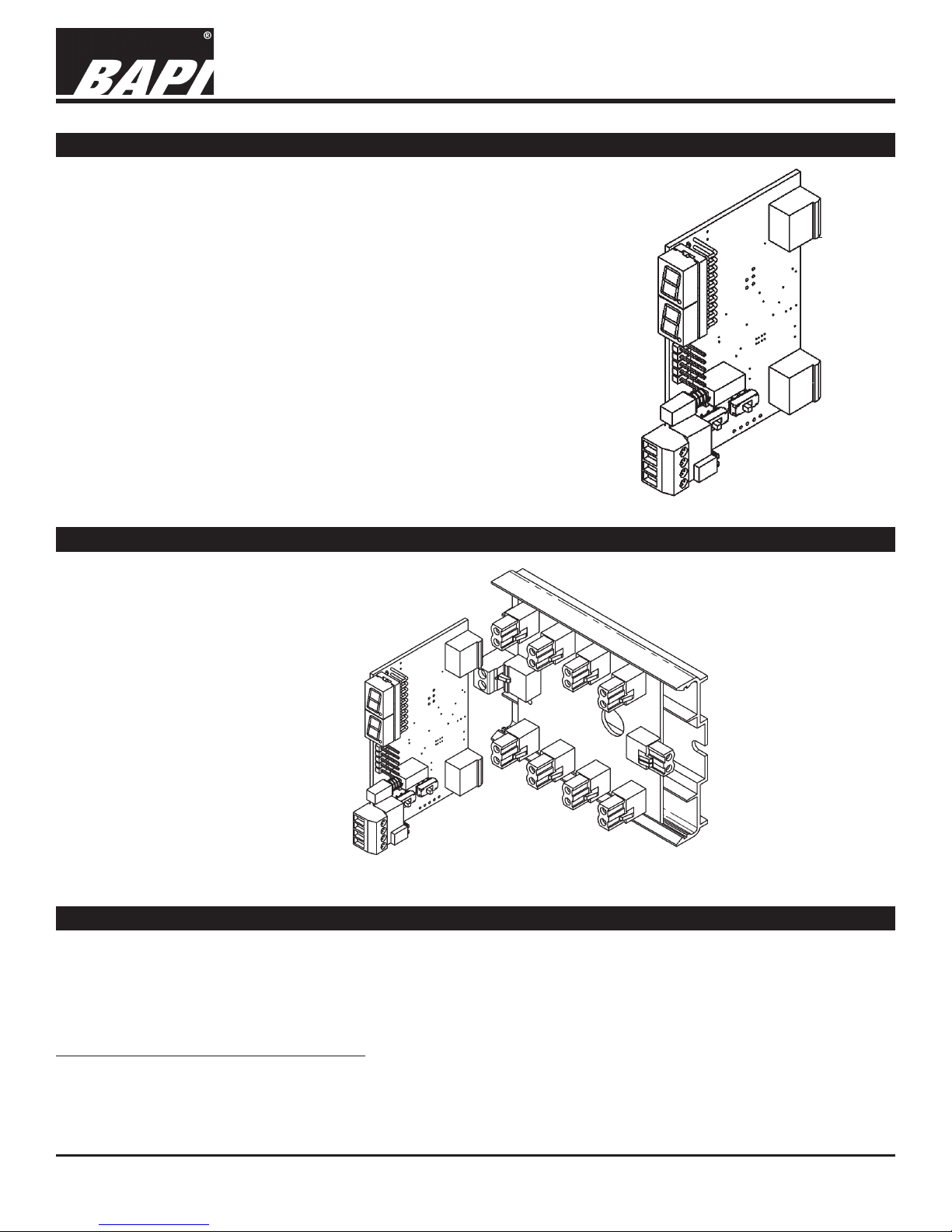
Fig. 1: SD2
Status Display
Module
The SD2 Module plugs into either a BP2,
BP4 or BP8 Backplane or BP4V Vertical
Backplane as shown in Fig. 2.
Fig. 2: SD2 Module plugging into
a BP4 Backplane
Specications
• Power Supply: MCP2456 switching regulator. Supplies 12V which is then dropped down by linear regulator
MCP1703 to 5V for the on-board circuitry, and acts as the reference for the ADC.
• Microprocessor: PIC16F1938 utilizing on-board ADC, LCD driver, UART, ISP and GPIO.
• Dual 7-segment display: LTS-1802
Power Voltage: 16 to 35VDC
Power Current: 50mA Max
Building Automation Products, Inc., 750 North Royal Avenue, Gays Mills, WI 54631 USA
Tel:+1-608-735-4800 • Fax+1-608-735-4804 • E-mail:sales@bapihvac.com • Web:www.bapihvac.com
Specications subject to change without notice.
1
Page 2
SD2 - Status Display, Dual 7-Segment Display
Installation and Operation Instructions
35827_ins_SD2.pdf
rev. 11/18/15
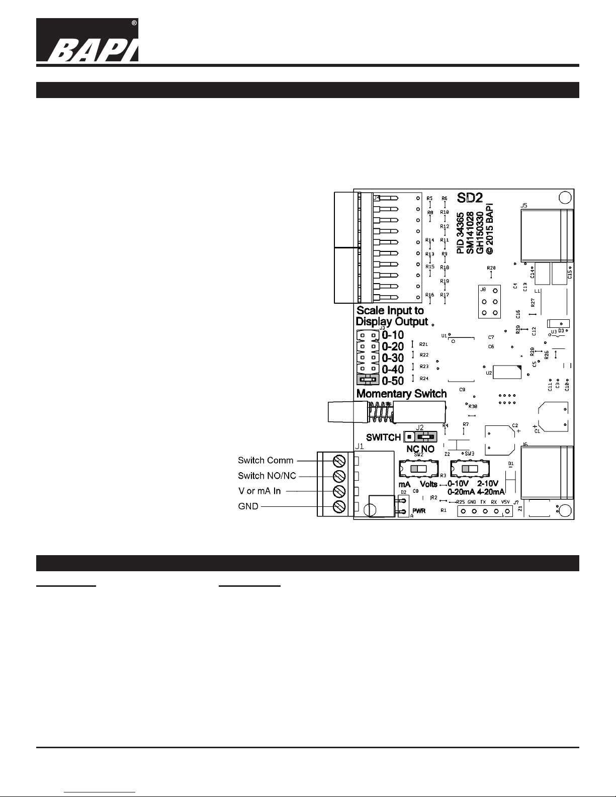
Termination
The SD2 is an ETA module that is used to indicate a program error code which requires a manual reset. The module
includes a manual reset switch that can be pressed to route a reset signal to a controller.
The SD module receives an input signal from a controller on Terminal 2 of J1, and then displays a number from 0
to 10 up to 0 to 50, depending on the jumper position of J3. It can accept a current input of either 0 to 20mA or 4
to 20mA or a voltage input of 0 to 10V or 2 to 10V. The type of input signal, current or volts, must be selected via
switch SW2, and the span of that input
signal must be selected via switch SW3.
The green LED indicates that power is
available to the module.
J2 - Reset Switch Mode Jumper
Denotes whether the switch is Normally
Open (NO) or Normally Closed (NC).
Pins 1-2 = NC
Pins 2-3 = NO (Factory Default)
SW2 - Input Mode Switch
Switches in the correct load to scale
the input for the microprocessor and
denotes to the processor what input
type is selected, mA or Volts. Factory
default is Volts.
SW3 - Span Switch
Denotes whether the span of the input
signal is 4 to 20mA or 0 to 20mA for
current input, or 0 to 10V or 2 to 10V
for voltage input. Factory default is
4 to 20mA/2 to 10V.
J3 - Display Range Selection Jumper
Sets the Display Range for the
7-Segment Display. Factory default is
0 to 10.
Pins 1-2 = 0 to 10 (Factory Default)
Pins 3-4 = 0 to 20
Pins 5-6 = 0 to 30
Pins 7-8 = 0 to 40
Pins 9-10 = 0 to 50
4
3
2
1
Fig. 3: SD2 Module component locator
Diagnostics
PROBLEMS
Green Power LED doesn’t light
No display on the digital output
Building Automation Products, Inc., 750 North Royal Avenue, Gays Mills, WI 54631 USA
Tel:+1-608-735-4800 • Fax+1-608-735-4804 • E-mail:sales@bapihvac.com • Web:www.bapihvac.com
SOLUTIONS
- Check to see if the SD2 is rmly inserted into the BP – Backplane
- Check the power cable to the BP – Backplane
- Check the power to the PS17 (or other external power supply that is
supplying power to the BP – Backplane) to see that it is supplying power
- Check to see if jumpers are correctly congured
- Check conguration of SW2 and SW3
- Check connections to J1
Specications subject to change without notice.
2
 Loading...