

Page 1
RµPS Room Unit with External Sensor
13406_ins_rups_ext_sen
Overview and Identication
The RµPS Room Unit with an External Sensor displays the temperature
where the external sensor is located. The unit can also provide a setpoint
adjustment value and occupancy override value to a controller. The unit
does NOT provide a temperature sensor value to the controller. A second
temperature sensor is required for the controller (see Figs 2 & 4).
The setpoint adjustment is a vertical slide pot with an analog output and a
Warm/Cool legend imprinted on the unit’s base. Optional setpoint indication
is available. The setpoint values can be a resistance or a voltage for easy
conguration with the controller. The occupancy override is available as a
separate output or in parallel with the Sensor or Setpoint. An optional LED
indicator is available on the face of the RµPS unit and is energized from
the controller. An optional 3.5mm (1/8”) or RJ11 communication jack can
be mounted in the base to provide direct access to the network. The sensor
and setpoint outputs can be congured for “common ground” or “differential
ground” controller inputs.
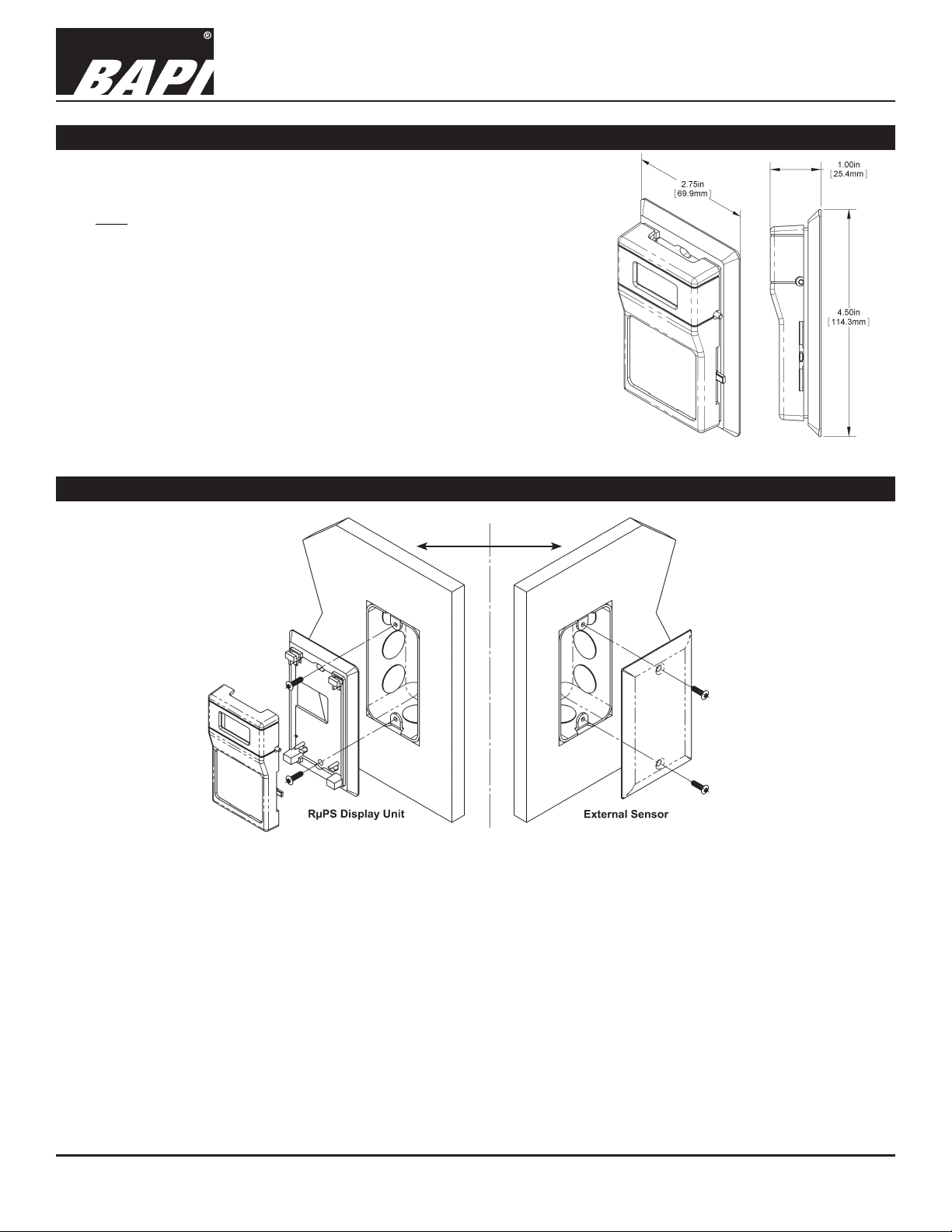
Mounting (on two sides of the same wall)
Installation and Operating Instructions
rev. 06/26/15
Fig 1: RµPS Display Unit Dimensions
24 Inch Limit
Fig 2:
RuPS Display
Unit and External
Sensor mounted
on opposite sides
of the same wall.
Note: The External
Sensor could be a Wall
Plate sensor (shown) or
a Return Air Sensor.
(All external sensors are
ordered seperately.)
1. Mount two junction boxes on opposite sides of the same wall. One side of the wall is the wall plate external sensor
and the other side of the wall is where the RuPS display unit will be installed. Place the boxes close enough together
that the wire on the wall plate and the display unit can reach one another.
2. Secure the RuPS display unit base to the junction box using the #6-32 x 1/2 inch mounting screws provided.
3. Run the wires from the wall plate through the junction box into the junction box for the RuPS display unit. Secure the
wall plate to the junction box with the #6-32 x 1/2 inch mounting screws provided making sure the foam on the back of
the wall plate makes a good seal with the wall.
4. Terminate the unit according to the Termination guidelines on page 1.
5. Attach RuPS Cover by latching it to the top of the base, rotating the cover down and snapping it into place.
6. Secure the RuPS cover by backing out the lock-down screws using a 1/16” Allen wrench until they are ush with the
bottom of the cover.
Specications subject to change without notice.
1 of 4
Page 2
RµPS Room Unit with External Sensor
Installation and Operating Instructions
13406_ins_rups_ext_sen
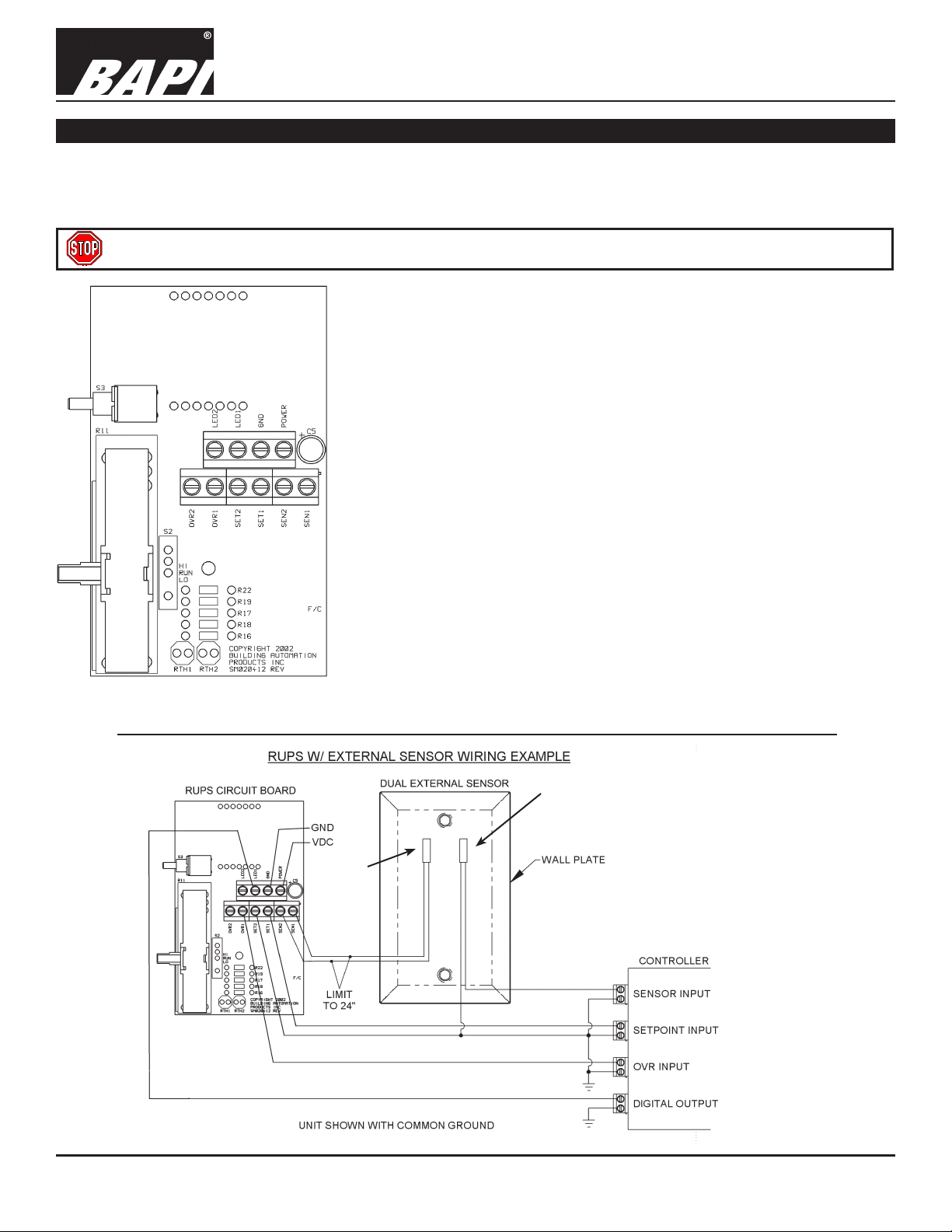
Termination
BAPI recommends using twisted pair of at least 22AWG and sealant lled connectors for all wire connections. Larger
gauge wire may be required for long runs. All wiring must comply with the National Electric Code (NEC) and local codes.
Do NOT run this device’s wiring in the same conduit as AC power wiring of NEC class 1, NEC class 2, NEC class 3 or with
wiring used to supply highly inductive loads such as motors, contactors and relays.
BAPI does not recommend wiring the sensor with power applied as accidental arcing may damage the product
and will void the warranty.
LED1 Short this terminal to Ground or Common to activate the
occupancy override LED on the front of the unit.
LED2 This terminal is only used if the unit is special ordered and the
customer wants to provide both power and ground to light the
occupancy override LED. Call BAPI tech support for more info.
GND Unit Ground or Common. Needs to be the same as the
controller’s Ground or Common.
POWER Unit power. 5 VDC (if 5 VDC option is selected when ordered)
9 to 40 VDC (15 to 24 VDC recommended)
15 to 28 VAC (requires a separate pair of shielded wires)
SEN1 & SEN2 10K-2 Thermistor input to the sensor display. No output to
controller. When unit is congured as Common Ground (CG),
SEN2 is internally shorted to the GND (Common) terminal.
SET1 & SET2 Temperature Setpoint Slider output. When unit is congured
as Common Ground (CG), SET2 is internally shorted to the
GND (Common) terminal.
OVR1 & OVR2 Occupancy Override Pushbutton, dry contact output. When
unit is congured as Common Ground (CG), OVR2 is internally
shorted to the GND (Common) terminal.
Notes:
Fig 3: RµPS Circuit Board
Test and Balance Switch is not available with an external sensor.
Common Ground (CG): GND, SEN2, SET2 & OVR2 are all internally connected.
Differential Ground (DG): GND, SEN2, SET2 & OVR2 are all internally isolated.
rev. 06/26/15
Must be
a 10K-2
Thermistor
Specications subject to change without notice.
Can be any sensor
specied for the
controller.
(This could also be
a Return Sensor)
Fig 4:
Dual External Sensor
Wiring Example with
a Common Ground
(CG) conguration.
2 of 4
Page 3

13406_ins_rups_ext_sen
Optional Communications Jack
(Male Jack shown for clarity)
C11L or C22L Wiring
RµPS Room Unit with External Sensor
Installation and Operating Instructions
rev. 06/26/15
Comm.
Jack
Fig. 5:
C35L Comm Jack
Fig. 6:
C35L Comm Jack in Unit’s Base.
(Front of unit base is shown at left, back of base at right)
Fig. 7:
C11L or C22L Comm
Jack
Fig. 8:
C11L or C22L Comm Jack in Unit’s Base.
(Front of unit base is shown at left, back of base at right)
Communications Jack Diagnostics
Possible Problems:
Comm. Jack has no connection to controller
Comm. Jack information received through wires is garbled
Possible Solutions:
- Conrm connection from patch cable to remote computer
- Make sure wires are tightly pressed in
- Check wiring for proper termination
- Check wiring for proper termination
- Verify that no wires are shorted together
Optional Settings for the RuPS Unit
OPTIONAL SETTINGS
Overrides: Override in parallel with the sensor or override as a separate input
External Sensor: 10K-2 Thermistor required
Setpoint: Resistive (Potentiometer) or 0 to 5VDC or 5 to 0VDC per order.
Comm.
Jack
CONTACT FACTORY WITH ANY DIFFERENT RANGE INQUIRIES
Common Ground (CG): Unit can be set up at factory (CG)
Differential Ground (DF): Unit can be set up at factory (DG)
Specications subject to change without notice.
3 of 4
Page 4

13406_ins_rups_ext_sen
Diagnostics
RµPS Room Unit with External Sensor
Installation and Operating Instructions
rev. 06/26/15
Possible Problems:
Unit will not operate
Temperature sensor in front end
software is reading is incorrect
LCD is not working
Sensor reading is signicantly off
from the LCD temperature
Possible Solutions:
- Check power supply/controller voltage supply
- Disconnect sensor power wires and check for power to sensor
- Verify the input is set up correctly in the front end software
- Check to see if the thermistor is damaged
- Check wiring for proper termination
- Compare temperature reading to the appropriate sensor table (See Note below)
- Verify that the unit has the proper voltage across the “Power” and “GND” circuit
board terminals. See power specications below proper power.
- Conrm that the sensor is wired correctly
- If outputs are correct but display is not operating, contact BAPI technical
support.
- Conrm that the sensor is wired correctly
- Compare temperature reading to appropriate sensor table (See Note below)
- Make sure the specied thermistor is correct
Note: To compare a reading to the appropriate sensor table, measure the physical
temperature at the temperature sensor’s location using an accurate temperature
standard. Disconnect the temperature sensor wires and measure the temperature
sensor’s resistance with an ohmmeter. Compare the temperature sensor’s
resistance to the appropriate temperature sensor table on the BAPI website. If the
measured resistance is different from the temperature table by more than 5%, call
BAPI technical support. BAPI’s website is found at www.bapihvac.com. Click on
the left menu link “Sensor Specs” and then click on the type of sensor you have.
Specications
Power:
5 VDC (only if 5 VDC option is selected when ordered)
9 to 40 VDC (15 to 24 VDC recommended)
15 to 28 VAC (Requires a separate pair of shielded wires)
Power Consumption:
10 mA max DC, .2 VA max AC
External Sensor Element and Accuracy:
Thermistor: 10K-2, ± 0.36ºF (±0.2ºC)
Wiring:
2 to 5 pair of 16 to 22 AWG
Communication Jack:
Option C35: 3.5mm (1/8”) phone jack
Option C11: RJ11
Option C22: RJ22
Specications subject to change without notice.
Mounting:
Standard 2” x 4” J-box or drywall (Mounting screws
provided)
Ambient:
32 to 122ºF (0 to 50ºC) 0 to 95% RH, Non-condensing
Material:
ABS plastic, UL94 HB
Override:
Contact N.O. as a separate closure or contact N.O. in
parallel with the setpoint
Setpoint:
Resistance (Potentiometer) or Voltage 0 to 5VDC or 5
to 0VDC
4 of 4
 Loading...