

Page 1
9522_ins_uni6_rsoc
Product Identication
Room temperature sensor with optional setpoint,
override, test & balance switch and comm. jack
Termination and Troubleshooting
BA/-RSOC
rev.06/24/15
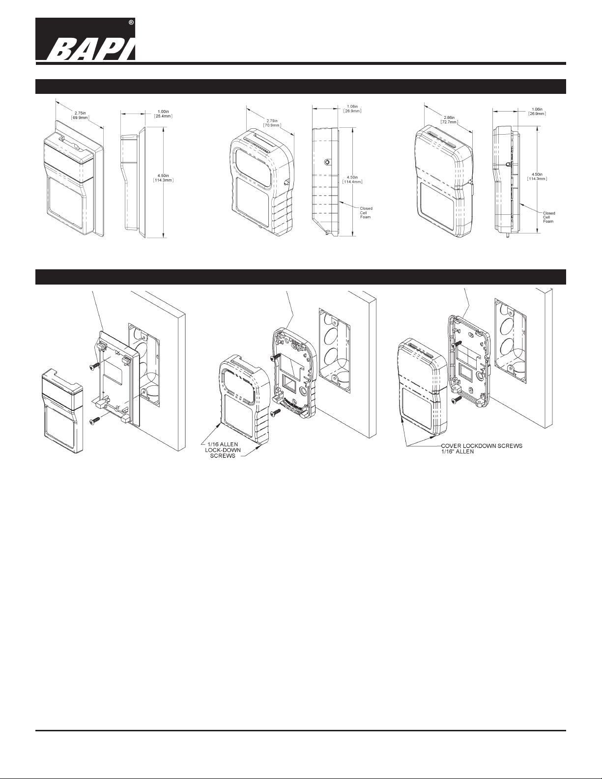
Fig. 1: Delta Style Fig. 2: BAPI-Stat 2
Mounting
Fig. 4:
Delta Style J-Box Mounting
Fig. 5:
BAPI-Stat 2 J-Box Mounting
Fig. 3: BAPI-Stat 4
Fig. 6:
BAPI-Stat 4 J-Box Mounting
Mounting hardware is provided for both junction box (J-box) and drywall installation (J-Box installation shown above).
JUNCTION BOX INSTRUCTIONS
1. Pull the wire through the wall and out of the junction box, leaving about six inches free.
2. Pull the wire through the hole in the base plate.
3. Secure the base to the box using the # 6-32 x 3/4 inch mounting screw provided.
4. Terminate the unit according to the guidelines in Termination on page 2.
5. Attach Cover by latching it to the top of the base, rotating the cover down and snapping it into place.
6. Secure the cover by backing out the lock-down screws using a 1/16” Allen wrench until they are ush with the bottom of the cover.
DRYWALL MOUNTING INSTRUCTIONS
1. Place the base plate against the wall where you want to mount the sensor.
2. Using a pencil mark out the two mounting holes and the area where the wires will come through the wall.
3. Drill two 3/16” holes in the center of each marked mounting hole. Insert a drywall anchor into each hole.
4. Drill one 1/2” hole in the middle of the marked wiring area.
Drywall Mounting Instructions continued on page 2...
Specications subject to change without notice.
1 of 4
Page 2
Room temperature sensor with optional setpoint,
override, test & balance switch and comm. jack
Termination and Troubleshooting
9522_ins_uni6_rsoc
Mounting continued...
5. Pull the wire through the wall and out of the 1/2” hole, leaving about six inches free.
6. Pull the wire through the hole in the base plate.
7. Secure the base to the drywall anchors using the #6 x 1 inch mounting screws provided.
8. Terminate the unit according to the guidelines in Termination on page 2.
9. Attach Cover by latching it to the top of the base, rotating the cover down and snapping it into place. Secure the cover
by backing out the lock-down screws using a 1/16” Allen wrench until they are ush with the bottom of the cover.
NOTE: In a wall-mount application, the wall temperature and the temperature of the air within the wall cavity can cause
erroneous readings. The mixing of room air and air from within the wall cavity can lead to condensation, erroneous readings and premature failure of the sensor. To prevent these conditions, seal the conduit leading to the junction box and seal
the hole in the drywall by using an adhesive backed, foam insulating pad (order part number BA/FOAMBACK-ROOM).
Termination
BAPI recommends using twisted pair of at least 22AWG and sealant lled connectors for all wire connections. Larger
gauge wire may be required for long runs. All wiring must comply with the National Electric Code (NEC) and local codes.
Do NOT run this device’s wiring in the same conduit as AC power wiring of NEC class, NEC class 2, NEC class 3 or with
wiring used to supply highly inductive loads such as motors, contactors and relays. BAPI’s tests show that uctuating
and inaccurate signal levels are possible when AC power wiring is present in the same conduit as the signal lines. If you
are experiencing any of these difculties, please contact your BAPI representative.
BA/-RSOC
rev.06/24/15
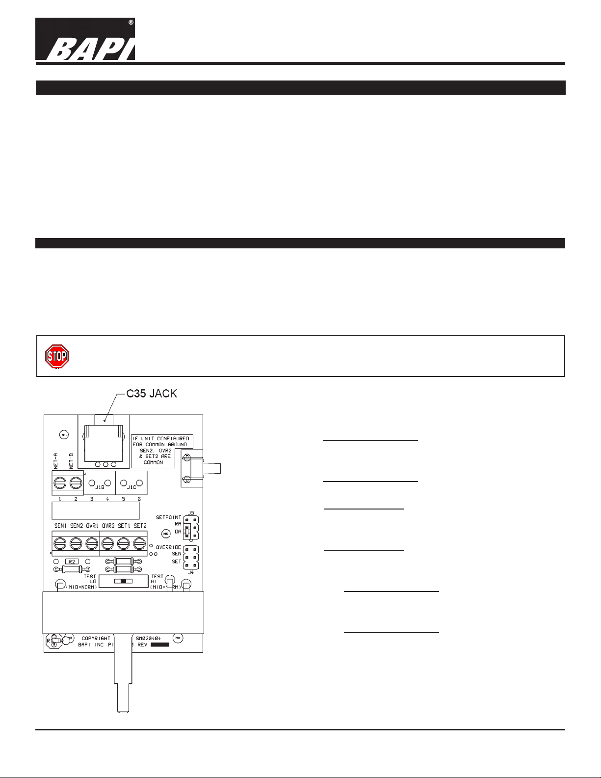
BAPI recommends wiring the product with power disconnected. Proper supply voltage, polarity, and
wiring connections are important to a successful installation. Not observing these recommendations may
damage the product and will void the warranty.
Common Wiring
SET 2
....Setpoint, Resistance Output, To analog input of controller
[Common Ground]
SET 1
OVR2
.....Setpoint, Resistance Output, To analog input of controller
.....Override, Normally OPEN, To analog or digital input of
controller [Common Ground]
OVR1
.....Override, Normally OPEN, To analog or digital input of
controller
SEN 2
....Temperature, Resistance Output, To analog input of
controller [Common Ground]
SEN 1
....Temperature, Resistance Output, To analog input of
controller
Fig. 7:
Circuit board
Note: If unit is congured for common ground, then SET2, OVR2 and
SEN2 are connected together.
Specications subject to change without notice.
2 of 4
Page 3

9522_ins_uni6_rsoc
Communication Jack Termination
Room temperature sensor with optional setpoint,
override, test & balance switch and comm. jack
Termination and Troubleshooting
BA/-RSOC
rev.06/24/15
Fig. 8:
C11 Comm
Jack
Fig. 9:
C12 Comm
Jack
Jumper Settings
C11 Wiring
1.... Not Connected
2.... [Internally connected to Comm Jack pin 2]
3.... [Internally connected to Comm Jack pin 3]
4.... [Internally connected to Comm Jack pin 4]
5.... [Internally connected to Comm Jack pin 5]
6.... Not Connected
C12 Wiring
1..... [Internally connected to Comm Jack pin 1]
2..... [Internally connected to Comm Jack pin 2]
3..... [Internally connected to Comm Jack pin 3]
4..... [Internally connected to Comm Jack pin 4]
5..... [Internally connected to Comm Jack pin 5]
6..... [Internally connected to Comm Jack pin 6]
Note: Male Jack shown for clarity
Fig. 10:
C35 Comm Jack
J5 Options
Setpoint Reverse
Acting (RA):
Setpoint Direct
Acting (DA):
Test & Balance Switch
Test and Balance Switch (S2)
High: Will set the sensor
value HIGH temperature
Norm: Thermistor/RTD
will operate normally
Low: Will set the sensor
value LOW temperature
J4 Differential Ground
Override in parallel with
setpoint:
Override in parallel with
sensor:
Override as a separate
input:
Sensor Type Low Temp (40° F) High Temp (105° F)
Resistance Value Resistance Value
1000Ω RTD 1.02KΩ (41.2°F) 1.15KΩ (101.5°F)
3000Ω Thermistor 7.87KΩ (39.5°F) 1.5KΩ (106.8°F)
10K-2 Thermistor 30.1KΩ (39.2°F) 4.75KΩ (105.8°F)
10K-3 Thermistor 26.7KΩ (35.9°F) 5.11KΩ (108.4°F)
10K-3(11K) Thermistor 7.32KΩ (43.7°F) 3.65KΩ (105.2°F)
J4 Common Ground
Override in parallel with
setpoint:
Override in parallel with
sensor:
Override as a separate
input:
Specications subject to change without notice.
3 of 4
Page 4

9522_ins_uni6_rsoc
Troubleshooting
Room temperature sensor with optional setpoint,
override, test & balance switch and comm. jack
Termination and Troubleshooting
BA/-RSOC
rev.06/24/15
Possible Problems:
Controller reports higher than actual
temperature
Controller reports lower than actual
temperature
Possible Solutions:
- Conrm the input is set up correctly in the front end software
- Verify that the wires are not physically shorted
- Check wiring for proper termination
- Verify the “Sensor” output is correct
- Is the “Sensor” output correct from (J2) Pin 1 to Pin 2
- Determine if the sensor is exposed to an external source
different from room environment (conduit draft)
- Fill box with Fiberglass, Polyester ll or plug the conduit.
- Conrm the input is set up correctly in the front end software
- Verify that the thermistor is not physically open
- Check wiring for proper termination
- Verify the “Sensor” output is correct
- Is the “Sensor” output correct from (J2) Pin 1 to Pin 2
- Determine if the sensor is exposed to an external source
different from room environment (conduit draft)
- Fill box with Fiberglass, Polyester ll or plug the conduit.
Setpoint is not working correctly
Override is not working correctly
Compare the readings to the appropriate temperature table on the BAPI website:
Click on the “Resource Library” and “Sensor Specs”, then select the table needed.
- Is the “Setpoint” output correct from (J2) Pin 5 to Pin 6.
- Are “J4” and “J5” set up correctly
- Check wiring for proper termination
- Is the output from (J2) Pin 3 to Pin 4 less than 50 ohms
when “S1” is used
- Check wiring for proper termination
http://www.bapihvac.com
Specications subject to change without notice.
4 of 4
 Loading...