

Page 1
Rigid Averaging Duct Transmitters
BA/# -RA Temperature Transmitter
Installation & Operations
20915_ins_DuctAvgRigid_Active
Overview
The BA/T#-RA is a rigid, stainless steel, averaging, duct mounted 4-20mA or Voltage temperature transmitter probe. It
comes in a variety of probe lengths and optional mounting enclosures shown below. The 4-20mA transmitter can be
ordered with 100Ω (385), 1KΩ (385) RTDs or 10KΩ type 2 thermistor sensors. A 0-5VDC or 0-10VDC transmitter is also
available with the 10KΩ type 2 thermistor sensor. Special high accuracy RTD matched transmitters (M) are available
which match the sensor to the transmitter for improved accuracy.
Identication
rev. 06/29/15
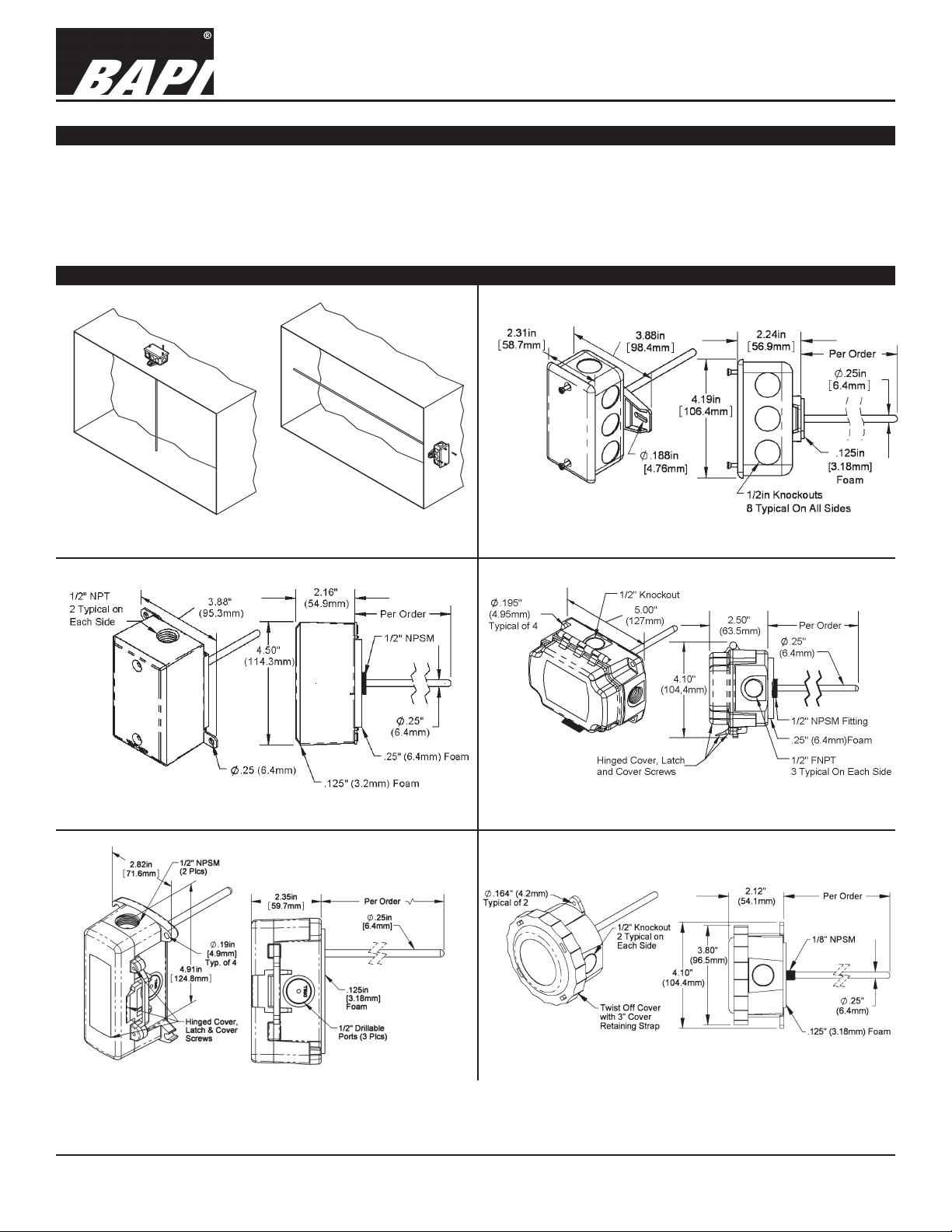
Fig 1: Typical Duct Mount Applications - Top Mount
(left) and Side Mount (right).
Fig 3: Duct Unit with Weatherproof (WP) Enclosure
Fig 2: Duct Unit with J-Box (Standard)
Fig 4: Duct Unit with BAPI-Box (BB) Enclosure
Fig 5: Duct Unit with BAPI-Box 2 (BB2) Enclosure
Specications subject to change without notice.
Fig 6: Duct Unit with Weather Tight (EU) Enclosure
1 of 4
Page 2
20915_ins_DuctAvgRigid_Active
Mounting
1. Place the sensor in the middle of
the duct going through temperature
stratied air, to achieve the best
temperature reading. (See Fig. 1)
2. Drill the probe hole as depicted
below for the enclosure being used.
(Handy Box, BB, BB2, WP, EU).
Insert the probe into the duct.
Rigid Averaging Duct Transmitters
BA/# -RA Temperature Transmitter
Installation & Operations
rev. 06/29/15
3. Mount the enclosure to the duct
using BAPI recommeded #8
screws through a minimum of two
opposing mounting tabs provided.
Weatherproof (WP) enclosures will
require assembly of the mounting
tabs on opposite corners. A 1/8
inch pilot screw hole in the duct
makes mounting easier through the
mounting tabs. Use the enclosure
tabs to mark the pilot hole locations.
4. Snug up the sensors so that the
foam backing is depressed to
prevent air leakage but do not overtighten or strip the screw threads.
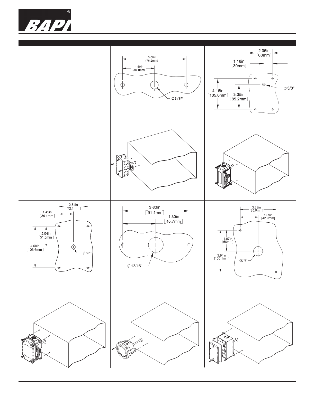
Fig 7:
Junction Box or No-Box (NB)
Mounting Holes
Fig 8: BAPI-Box 2 (BB2)
Enclosure Mounting Holes
Fig 9: BAPI-Box (BB) Enclosure
Mounting Holes, Rotate 90° for
Horizontal Mounting
Fig 10:
Weather Tight (EU or EUO)
Enclosure Mounting Holes
Specications subject to change without notice.
Fig 11:
Weatherproof (WP) Enclosure
Mounting Holes
2 of 4
Page 3

Rigid Averaging Duct Transmitters
BA/# -RA Temperature Transmitter
Installation & Operations
20915_ins_DuctAvgRigid_Active
Wiring & Termination
BAPI recommends using twisted pair of at least 22AWG and sealant lled connectors for all wire connections. Larger
gauge wire may be required for long runs. All wiring must comply with the National Electric Code (NEC) and local codes.
Do NOT run this device’s wiring in the same conduit as high or low voltage AC power wiring. BAPI’s tests show that inaccurate signal levels are possible when AC power wiring is present in the same conduit as the sensor wires.
rev. 06/29/15
Fig. 17: Typical
RTD 4 to 20mA
Transmitter with
Terminals
Fig. 18: Typical Thermistor
4 to 20mA Transmitter
Fig. 16: Typical
RTD 4 to 20 mA
Transmitter with
Flying Leads
Fig. 19: Typical Thermistor
Voltage Transmitter
Diagnostics
Possible Problems: Possible Solutions:
•
Unit will not operate. - Measure the power supply voltage by placing a voltmeter across the transmitter’s (+) and
- Check if the RTD wires are physically open or shorted together and are terminated to the
- Measure the physical temperature at the temperature sensor’s location using an accurate
(-) terminal. Make sure that it matches the drawings above and power requirements in the
specications.
transmitter.
temperature standard. Disconnect the temperature sensor wires and measure the
temperature sensor’s resistance with an ohmmeter. Compare the temperature sensor’s
resistance to the appropriate temperature sensor table on the BAPI web site.
• The reading is incorrect in the controller.
- For a 4 to 20mA current transmitter measure the transmitter current by placing an
Voltage Temperature Equation
T = TLow + (V x TSpan)
VSpan
T = Temperature at sensor
TLow = Low temperature of span
THigh = High temperature of span
TSpan = THigh - TLow
VLow = Low transmitter voltage
usually=(0, 1 or 2v)
VHigh = High transmitter voltage
usually=(5 or 10v)
VSpan = VHigh - VLow
V = Signal reading in volts
- Determine if the input is set up correctly in the controllers and BAS software.
ammeter in series with the controller input. The current should read according to the “4 to
20mA Temperature Equation” shown below.
- For a voltage transmitter, measure the signal with a volt meter (Orange or Orange/Black to
Black). The signal should read according to the “Voltage Temperature Equation” shown below.
4 to 20mA Temperature Equation
T = TLow + (A -4) x (TSpan)
16
T = Temperature at sensor
TLow = Low temperature of span
THigh = High temperature of span
TSpan = THigh - TLow
A = Signal reading in mA
Specications subject to change without notice.
3 of 4
Page 4

20915_ins_DuctAvgRigid_Active
Specications
RTD Transmitter
Power Required: 7 to 40VDC
Transmitter Output: 4 to 20mA, 850Ω@24VDC
Output Wiring: 2 wire loop
Output Limits: <1mA (short), <22.35mA (open)
Span:
Zero:
Zero & Span Adjust: 10% of span
Accuracy: ±0.065% of span
Linearity: ±0.125% of span
Power Output Shift: ±0.009% of span
RTD Sensor: 2 wire Platinum (Pt), 385 curve
Transmitter Ambient -4 to 158ºF(-20 to 70ºC)
0 to 95% RH, Non-condensing
Thermistor Transmitter
Supply Voltage:
10 to 35 VDC (0 to 5 VDC or 4 to 20 mA Outputs)
15 to 35 VDC (0 to 10 VDC Output)
12 to 24 VAC (0 to 5 VDC Outputs)
15 to 24 VAC (0 to 10 VDC Output)
Transmitter Output: 4 to 20mA, 700Ω@24VDC
0 to 5 & 0 to 10VDC, 10KΩ min
Output Wiring: 2 & 3 wire (See wiring detail on pg. 3)
Transmitter Limits: -40 to 185ºF, (-40 to 85ºC)
Accuracy: ±1.015ºC, from (0 to 65ºC)
Linearity: ±0.065ºC, from (0 to 65ºC)
Resolution: Span/1024
Thermistor Sensor: 10K-2 Thermistor, 10KΩ @77ºF
Transmitter Ambient: 32 to 158ºF, (0º to 70ºC)
0 to 95% RH, Noncondensing
Thermistor: 10K-2,Thermal Resistor (Bare Sensor)
Accuracy (Std): ±0.36ºF, (±0.2ºC)
Accuracy (High): ±0.18ºF, (±0.1ºC), [XP] option
Stability: < 0.036ºF/Year, (<0.02ºC/Year)
Heat Dissipation: 2.7 mW/ºC
Probe Range: -40º to 221ºF (-40º to 105ºC)
Wire Colors:
Standard: Yellow/Yellow (no polarity)
High Acc. [XP]: Yellow/Yellow (no polarity)
RTD:
Platinum (Pt): 100Ω and 1KΩ @0ºC, 385 curve,
Pt Accuracy (Std): 0.12% @Ref, or ±0.55ºF, (±0.3ºC)
Pt Accuracy (High): 0.06% @Ref, or ±0.277ºF,
(±0.15ºC), [A]option
Pt Stability: ±0.25ºF, (±0.14ºC)
Pt Self Heating: 0.4 ºC/mW @0ºC
Pt Probe Range: -40º to 221ºF, (-40 to 105ºC)
Wire Colors:
1KΩ, Class B Orange/Orange (no polarity)
1KΩ, Class A Orange/White (no polarity)
100Ω, Class B Red/Red (no polarity)
100Ω, Class A Red/Red-w/black stripe (no polarity)
Min. 30ºF (17ºC), Max 1000ºF, (555ºC)
Min. -148°F (-100°C), Max 900ºF (482ºC)
Resistance Temp Device (Bare Sensor)
General color code (other colors possible)
Rigid Averaging Duct Transmitters
BA/# -RA Temperature Transmitter
Installation & Operations
rev. 06/29/15
Sensitivity: Approximate @ 32ºF (0ºC)
Thermistor: Non-linier - (See www.bapihvac.com,
click “Sensor Specs”)
RTD (Pt): 3.85Ω/ºC for 1KΩ RTD
0.385Ω/ºC for 100Ω RTD
Lead Wire: 22awg stranded
Insulation: Etched Teon, Plenum rated
Probe: Rigid Stainless Steel, 0.25”OD
Probe Length:
Duct Gasket: 1/4” Closed cell foam (impervious to mold)
Mounting: Extension tabs (ears), 3/16” holes
Enclosure Types: (Part number designator in bold)
J-Box: -JB, w/ eight ½” knock-outs
Weatherproof: -WP, w/ two ½” FNPT entries, (Bell box)
BAPI-Box: -BB, w/ four ½” NPSM & one ½” drill-out
BAPI-Box 2:
Weather Tight: -EU, EUO, w/ two ½” knock-outs
Enclosure Ratings: (Part number designator in bold)
J-Box: -JB, NEMA 1
Weatherproof: -WP, NEMA 3R, IP14
BAPI-Box: -BB, NEMA 4, IP66, UV Rated
BAPI-Box 2: -BB2, NEMA 4, IP66, UV Rated
Weather Tight: -EU, NEMA 4, IP66
Weather Tight: -EUO, NEMA 4, IP66, UV rated
Enclosure Material: (Part number designator in bold)
J-Box: -JB, UL94H-B
Weatherproof: -WP, Cast Aluminum, UV rated
BAPI-Box: -BB, Polycarbonate, UL94V-0, UV rated
BAPI-Box 2: -BB2, Polycarbonate, UL94V-0, UV rated
Weather Tight: -EU, ABS Plastic, UL94V-0
Weather Tight: -EUO, ASA (Geloy) Plastic, UL94V-0, UV rated
Ambient (Encl.) 0 to 100% RH, Non-condensing
J-Box -JB, -40ºF to 212ºF, (-40º to 100ºC)
Weatherproof -WP, -40ºF to 212ºF, (-40º to 100ºC)
BAPI-Box -BB, -40ºF to 185ºF, (-40º to 85ºC)
BAPI-Box 2 -BB2, -40ºF to 185ºF, (-40º to 85ºC)
Weather Tight -EUO, EU, -40ºF to 185ºF, (-40º to 85ºC)
Agency RoHS
PT=DIN43760, IEC Pub 751-1983,
JIS C1604-1989
12", 2’ or 4’ per order
-BB2, w/ three ½” NPSM & three ½” drill-outs
Related Products
BA/SFC1000-100 Sealant lled crimp connectors (100 connectors)
BA/SFC2000-100 Sealant lled crimp twist on wire nuts (100 nuts)
Specications subject to change without notice.
4 of 4
 Loading...