

Page 1
Replaceable Sensor Probes
BA/#-P-x, BA/#xP, BA/HxS
Installation & Operations
20912_ins_Repl_Probe_Passive
Overview
• The BA/#-P-x is a Stainless Steel Replacement probe for use with any BAPI Immersion, or Duct temperature
sensor. They come in a variety of lengths and with TFE insulated plenum cable. The BA/#-P-x sensor is
available in multiple types of thermistor’s or RTD temperature sensors as shown in the specifications. The
probe comes without a box and is made to insert into an existing duct or immersion box fitting as a replacement. It is ideal to replace a damaged probe or to change the length of an existing probe installation.
• The BA/#-HxP is a Humidity Replacement probe w/sintered filter for use with any BAPI Duct or OSA RH
transmitter. They come pre-calibrated and ready to install and use. The BA/#-HxP probe is available with
multiple types of thermistor’s or RTD temperature sensors as shown in the specifications. The replacement
probe comes without a box and is made to thread into an existing duct or OSA enclosure. It is ideal to
replace a damaged probe or worn-out sensor in an existing installation. Replacement 100 micron SS
sintered filters as well as wash down caps are also available. No field calibration is required.
• The BA/#-HxS is a Humidity Sensor Replacement for BAPI room RH transmitters. They come pre-cali-
brated and ready to install and use. No field calibration is required.
Identification
10/1/09 rev.
Per OrderPer Order
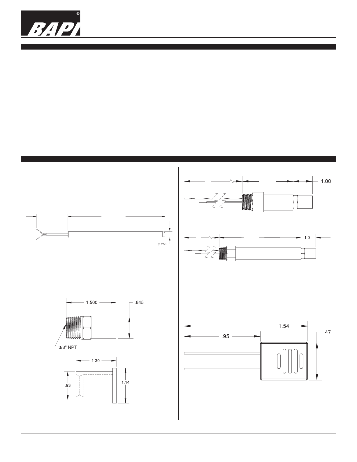
Fig 1: SS Replacement Sensor Probe (BA/#-P-X)
FILTER
6”
6”
2.125”
OSA
5.25”
DUCT
Fig 2: Replacement RH Probe (BA/#-HxP)
CAP
Fig 3: Replacement Sintered Filter & Washdown Cap
(BA/HDOFS), (BA/VFC)
Specifications subject to change without notice.
Fig 4: Replacement Room RH Sensor (BA/#-HxS)
1 of 4
Page 2
20912_ins_Repl_Probe_Passive
Mounting
•
Replaceable Sensor Probes
BA/#-P-x, BA/#xP, BA/HxS
Installation & Operations
10/1/09 rev.
•
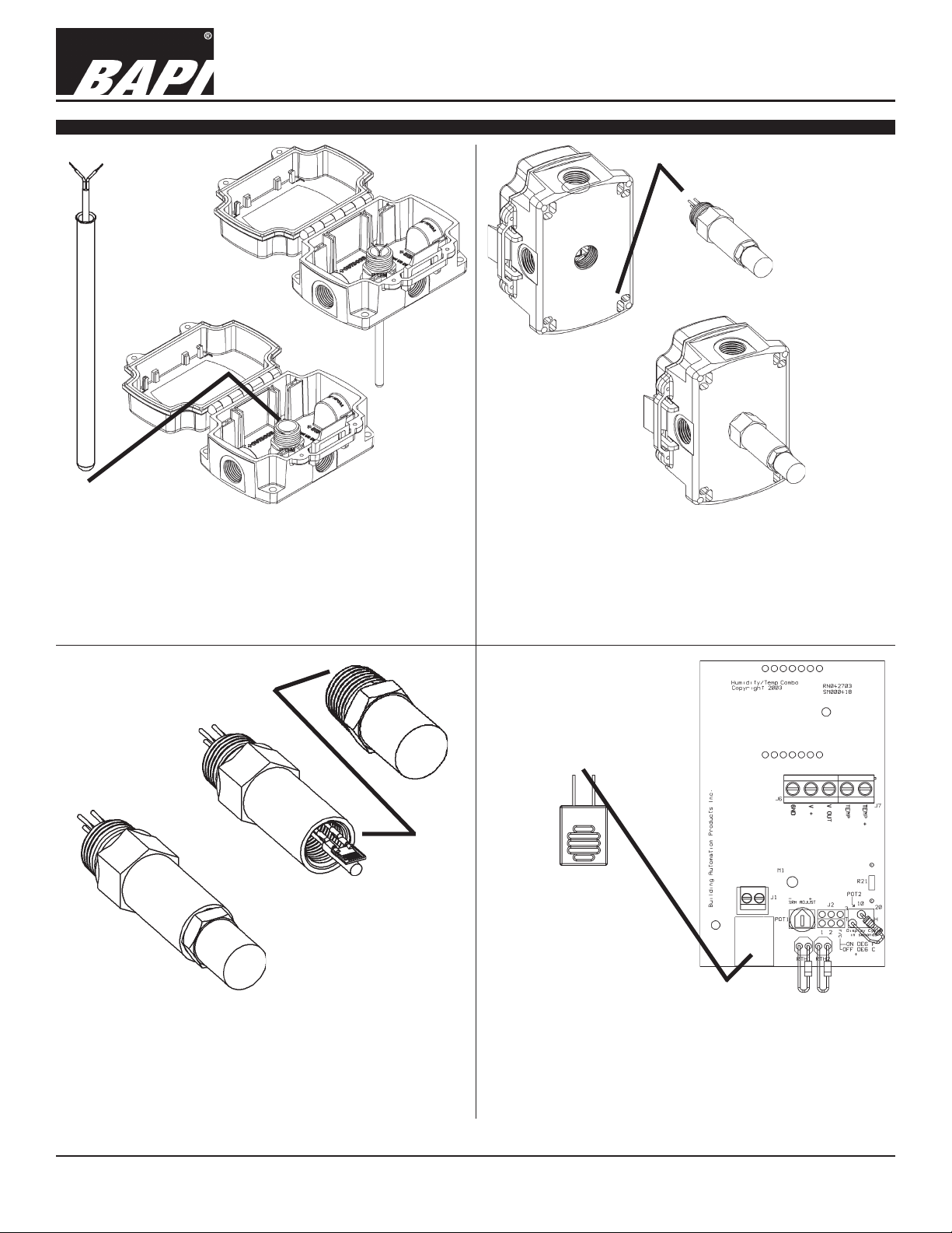
Fig 5: Typical Temperature Sensor probe replacement
1. Open the box and disconnect the wires.
2. Push the old probe into the box and out through the plastic fitting.
3. Push the new probe into the box and into the plastic fitting all the
way to the flared end.
4. Pull the probe to full extension and re-connect per termination
section.
•
Fig 6: Typical Humidity Transmitter Probe Replacement
1. Un-install the box and disconnect the wires from the transmitter.
Note color code.
2. Un-screw (CCW) the old 1/2” NPT probe from the back of the box.
3. Screw in (CW) the new 1/2” NPT probe into the back of the box.
4. Install and re-connect the wires per the color code and termination
section.
NOTE: No callibration is needed.
•
Fig 7: Typical Humidity Probe Filter Replacement
1. Un-screw (CCW) the old 1/2” stainless steel filter.
2. Fully screw in (CW) the new 1/2” stainless steel filter.
NOTE: The old filter can be cleaned for future use with
soap & water and then rinse thoroughly.
Specifications subject to change without notice.
Fig 8: Typical Room RH Sensor Replacement
1. Take the sensor cover off using a 1/16” Allen wrench.
2. Un-screw terminals J1 and remove the old blue RH sensor.
3. Install new sensor leads in the terminals with vents facing up.
4. Install the sensor cover.
NOTE: No calibration is required.
2 of 4
Page 3

20912_ins_Repl_Probe_Passive
Temperature Probe Termination
Sensor
Replaceable Sensor Probes
BA/#-P-x, BA/#xP, BA/HxS
Installation & Operations
10/1/09 rev.
Fig 9: 2 Wire Thermistor or RTD
RH Probe Termination
To Controller Analog
Input or Transmitter
(AI) (No Polarity)
Sensor
Fig 10:
To 3 Wire Transmitter
3 Wire RTD
Fig 11: 4-20mA RH Probe With or Without RTD Temp. Transmitter
RH Probe Termination
Voltage Sensor Output
Ground
Power
Fig 13: Voltage RH Probe With or Without Passive Sensor
Specifications subject to change without notice.
Fig 12: RH Probe With Thermistor Transmitter
Sensor Terminals
•
Sensor
•
Fig 6: Room Replacement RH Sensor
3 of 4
Page 4

Replaceable Sensor Probes
BA/#-P-x, BA/#xP, BA/HxS
Installation & Operations
20912_ins_Repl_Probe_Passive
Diagnostics
Problems:
Controller reports higher or lower than
actual temperature
Humidity not reading - Check power supply/controller voltage supply
Humidity Sensor/Transmitter Check: - Reconnect all the wires as shown in the wiring details for your
Specifications
Temperature Sensor:
Thermistor NTC, 2 wire
RTD PTC, 2 or 3 wire
Thermistor Thermal resistor
Temp. Output Resistance
Accuracy (std) ±0.36ºF, (±0.2ºC)
Accuracy (Hi) ±0.18ºF, (±0.1ºC), [XP] option
Stability < 0.036ºF/Year, (<0.02ºC/Year)
Heat dissipation 2.7 mW/ºC
Temp. Drift <0.02ºC per year
Probe range -40º to 221ºF (-40º to 105ºC)
RTD Resistance Temperature Device
Platinum (PT) 100Ω or 1KΩ @0ºC, 385 curve,
Platinum (PT) 1KΩ @0ºC, 375 curve
PT Accuracy (std) 0.12% @Ref, or ±0.55ºF, (±0.3ºC)
PT Accuracy (Hi) 0.06% @Ref, or ±0.277ºF,
(±0.15ºC), [A]option
PT Stability ±0.25ºF, (±0.14ºC)
PT Self Heating 0.4 ºC/mW @0ºC
PT Probe range -40º to 221ºF (-40º to 105ºC)
Nickel (Ni) 1000Ω@70ºF, JCI curve
Ni Probe range -40º to 221ºF (-40º to 105ºC)
Sensitivity bapihvac.com click “Sensor Specs”
Thermistor Non-linier
RTD (PT) 3.85Ω/ºC for 1KΩ RTD
0.385Ω/ºC for 100Ω RTD
Nickel (Ni) 2.95Ω/ºF for the JCI RTD
Lead wire 22awg stranded
Wire Insulation FEP jacketed plenum rated cable
Probe Rigid, 304 Stainless Steel, 0.25" OD
Mounting Inserted into Plastic Fitting
Agency RoHS, CE
PT= DIN43760, IEC Pub 751-1983,
JIS C1604-1989
Possible Solutions:
- Confirm the input is set up correctly in the front end software
- Check wiring for proper termination & continuity. (shorted or open)
- Disconnect wires and measure sensor resistance and verify “Sensor”
output is correct.
- Disconnect humidity transmitter and check for correct power
- Connect power and then check signal wiring with a meter.
- Check for proper signal wiring to the controller.
- Open one of the blue wire connections. The transmitter should
read 0% RH, if not the transmitter may be bad.
- Short out the blue wires. The transmitter should read 100% RH.
If not the transmitter may be bad.
sensor type and power up the transmitter. You should be
reading the relative humidity at the output. Check this reading
with a trusted hygrometer reference. If it’s off by more than the
added ± accuracy of the hygrometer accuracy plus the trans
mitter accuracy the combined sensor/transmitter is bad or
needs factory calibration. (±2% + ±3% = ±5% total accuracy)
RH Sensor and Probe:
Sensor:
Humidity Resistive (Impedance)
Temp. Per sensor spec above
Filter: 100 micron sintered stainless steel
Wiring:
Duct Probe RH- 4 flying leads, Opt. Temp.-
2 flying leads
OSA Probe RH- 4 flying leads, Opt. Temp.-
2 flying leads
Room Board mounted Terminals
Probe Termination Required:
Sealant filled crimp connectors, (BA/SFC1000-100)
Accuracy:
H2P, H2S 2%, from 15% to 95%RH @77ºF
H3P, H2S 3%, from 15% to 95%RH @77ºF
Probe Material:
Duct ABS Plastic, UL94V-HB
OSA Polycarbonate, UV resistant,
UL94V-HB
Environmental Ambient Range:
-22º to 158ºF, (-30º to 70ºC)
0% to 100% RH
10/1/09 rev.
Specifications subject to change without notice.
4 of 4
 Loading...