

Page 1
Remote Probe Transmitters and Remote Sensor Transmitters
BA/#-(PP, RPP, RPFEP) Temperature Sensor
Installation & Operations
20921_ins_RemoteSen_Active
Overview
• The BA/#-PP is a small temperature conductive plastic sensor used for single point temperature measurement with twin plenum
rated lead wires. It is ideal for mounting applications inside electronic circuit enclosures or existing thermostats.
• The BA/#-RPP is a small Stainless Steel (SS) temperature sensor used for single point temperature measurement with PVC
plenum rated cable. It is ideal for bracket mounting for Chamber, Duct, Thermowell or L-bracket applications.
• The BA/#-RPFEP is a small Stainless Steel (SS) temperature sensor used for single point temperature measurement with FEP
plenum cable. It is ideal for bracket mounting in harsh environments for Chamber, Duct, Thermowell or L-bracket applications.
• The BA/#-RPFEP2 is a small Stainless Steel (SS) temperature sensor used for single point temperature measurement with
submersion FEP plenum cable. It is ideal for bracket mounting in wet or water submersion environments for Chamber, Duct,
Immersion or L-bracket applications.
The BA/#-(PP, RPP, RPFEP, RPFEP2) units are available in multiple types of 4 to 20mA transmitters that can be ordered with
100Ω (385), 1KΩ (385) RTDs or 10KΩ type 2 thermistor sensors. A 0 to 5VDC or 0 to 10VDC transmitter is also available with
the 10KΩ type 2 thermistor sensor. Special high accuracy RTD matched transmitters (M) are available which match the sensor
to the transmitter for improved accuracy. Enclosure mounting styles come in plastic or metal for both NEMA 3R and NEMA 4
applications and are all plenum rated.
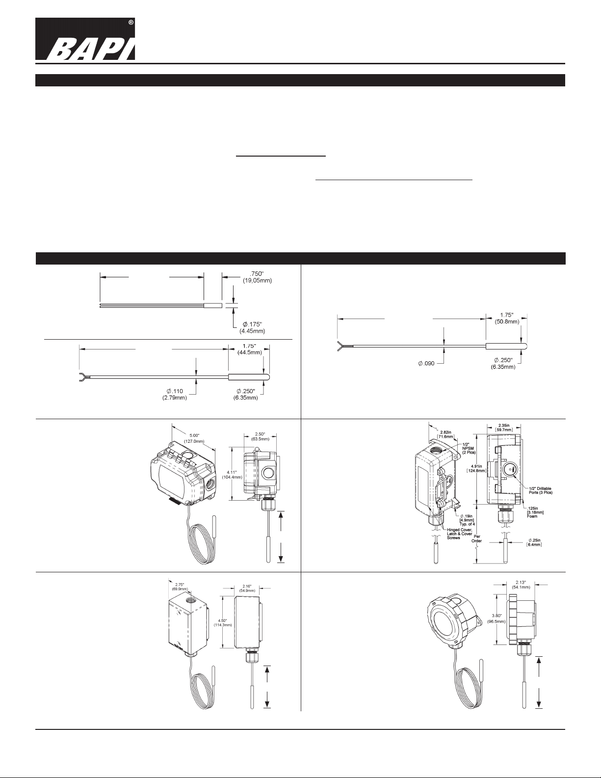
Identication
Per Order
rev. 06/30/15
Fig 1: Remote Sensor with Epoxy Shell
Per Order
Fig 2: Stainless Steel Remote Probe with Plenum-rated Cable
Fig 4: Stainless Steel Remote
Probe in a BAPI-Box
(BB) Enclosure
Per
Order
Per Order
Fig 3: Stainless Steel Remote Probe with FEP Plenum Cable
Fig 5: Stainless Steel
Remote Probe in a
BAPI-Box 2 (BB2)
Enclosure
Fig 6: Stainless Steel Remote
Probe in a Weatherproof
(WP) Enclosure
Fig 7: Stainless Steel Remote
Probe in a Weather
Per
Order
Specications subject to change without notice.
Tight (EU, EUO)
Enclosure
Per
Order
1 of 4
Page 2
20921_ins_RemoteSen_Active
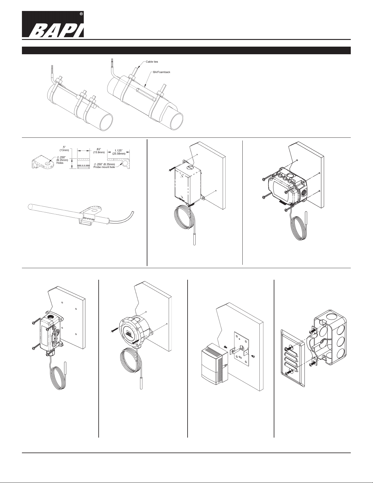
Mounting
Step 1
Remote Probe Transmitters and Remote Sensor Transmitters
BA/#-(PP, RPP, RPFEP) Temperature Sensor
Installation & Operations
rev. 06/30/15
Step 1: Secure Sensor To Have Good Contact With Bare Pipe
Step 2: Insulate Over The Sensor (See Notes Below)
Notes: Insulation should be installed a minimum of 4 pipe
diameters on each side of the strap-on sensor.
Example: ½” pipe x 4 = 2”.
Insulation should be 2” on each side of the sensor wrapped all
the way around the pipe.
Step 2
Fig 8: Stainless Steel Remote Probes Strapped to Pipes
Fig 9-A: Break-Off Tab from a BAPI
Flexible Probe Bracket (BA/FP)
Fig 9-B: Break-Off Tab Used to
Mount a Stainless Steel
Remote Probe.
Fig 10: Stainless Steel Remote
Probe with Weatherproof
(WP) Enclosure
Fig 11: Stainless Steel Remote
Probe with BAPI-Box (BB)
Enclosure
Fig 12: Stainless Steel
Remote Probe with
BAPI-Box 2 (BB2)
Enclosure
Fig 13: Stainless Steel
Remote Probe
with Weather
Tight (EU, EUO)
Enclosure
Specications subject to change without notice.
Fig 14: Remote Sensor
Shown Installed in a
Pneumatic Thermostat
Fig 15: Remote Sensor
Shown Installed in
an Junction Box
with a Wall Plate
Cover
2 of 4
Page 3

Remote Probe Transmitters and Remote Sensor Transmitters
BA/#-(PP, RPP, RPFEP) Temperature Sensor
Installation & Operations
20921_ins_RemoteSen_Active
Wiring & Termination
BAPI recommends using twisted pair of at least 22AWG and sealant lled connectors for all wire connections. Larger
gauge wire may be required for long runs. All wiring must comply with the National Electric Code (NEC) and local codes.
Do NOT run this device’s wiring in the same conduit as high or low voltage AC power wiring. BAPI’s tests show that inaccurate signal levels are possible when AC power wiring is present in the same conduit as the sensor wires.
rev. 06/30/15
Fig. 17: Typical
RTD 4 to 20mA
Transmitter with
Terminals
Fig. 18: Typical Thermistor
4 to 20mA Transmitter
Fig. 16: Typical
RTD 4 to 20 mA
Transmitter with
Flying Leads
Fig. 19: Typical Thermistor
Voltage Transmitter
Diagnostics
Possible Problems: Possible Solutions:
•
Unit will not operate. - Measure the power supply voltage by placing a voltmeter across the transmitter’s (+) and
- Check if the RTD wires are physically open or shorted together and are terminated to the
- Measure the physical temperature at the temperature sensor’s location using an accurate
(-) terminal. Make sure that it matches the drawings above and power requirements in the
specications.
transmitter.
temperature standard. Disconnect the temperature sensor wires and measure the
temperature sensor’s resistance with an ohmmeter. Compare the temperature sensor’s
resistance to the appropriate temperature sensor table on the BAPI web site.
• The reading is incorrect in the controller.
- For a 4-20mA current transmitter measure the transmitter current by placing an ammeter
Voltage Temperature Equation
T = TLow + (V x TSpan)
VSpan
T = Temperature at sensor
TLow = Low temperature of span
THigh = High temperature of span
TSpan = THigh - TLow
VLow = Low transmitter voltage
usually=(0, 1 or 2v)
VHigh = High transmitter voltage
usually=(5 or 10v)
VSpan = VHigh - VLow
V = Signal reading in volts
- Determine if the input is set up correctly in the controllers and BAS software.
in series with the controller input. The current should read according to the “4-20mA
Temperature Equation” shown below.
- For a voltage transmitter, measure the signal with a volt meter (Orange or Orange/Black to
Black). The signal should read according to the “Voltage Temperature Equation” shown below.
4-20mA Temperature Equation
T = TLow + (A -4) x (TSpan)
16
T = Temperature at sensor
TLow = Low temperature of span
THigh = High temperature of span
TSpan = THigh - TLow
A = Signal reading in mA
Specications subject to change without notice.
Page 4

20921_ins_RemoteSen_Active
Specications
Remote Probe Transmitters and Remote Sensor Transmitters
BA/#-(PP, RPP, RPFEP) Temperature Sensor
Installation & Operations
rev. 06/30/15
RTD Transmitter
Power Required: 7 to 40VDC
Transmitter Output: 4 to 20mA, 850Ω@24VDC
Output Wiring: 2 wire loop
Output Limits: <1mA (short), <22.35mA (open)
Span:
Zero:
Min. 30ºF (17ºC), Max 1000ºF, (555ºC)
Min. -148°F (-100°C), Max 900ºF (482ºC)
Zero & Span Adjust: 10% of span
Accuracy: ±0.065% of span
Linearity: ±0.125% of span
Power Output Shift: ±0.009% of span
RTD Sensor: 2 wire Platinum (Pt), 385 curve
Transmitter Ambient -4 to 158ºF(-20 to 70ºC)
0 to 95% RH, Non-condensing
Thermistor Transmitter
Supply Voltage:
10 to 35 VDC (0 to 5 VDC or 4 to 20 mA Outputs)
15 to 35 VDC (0 to 10 VDC Output)
12 to 24 VAC (0 to 5 VDC Outputs)
15 to 24 VAC (0 to 10 VDC Output)
Transmitter Output: 4 to 20mA, 700Ω@24VDC
0 to 5 & 0 to 10VDC, 10KΩ min
Output Wiring: 2 & 3 wire (See wiring detail on pg. 3)
Transmitter Limits: -40 to 185ºF, (-40 to 85ºC)
Accuracy: ±1.015ºC, from (0 to 65ºC)
Linearity: ±0.065ºC, from (0 to 65ºC)
Resolution: Span/1024
Thermistor Sensor: 10K-2 Thermistor, 10KΩ @77ºF
Transmitter Ambient: 32 to 158ºF, (0º to 70ºC)
0 to 95% RH, Noncondensing
Thermistor:
10K-2,Thermal Resistor (Bare Sensor)
Accuracy (Std): ±0.36ºF, (±0.2ºC)
Accuracy (High): ±0.18ºF, (±0.1ºC), [XP] option
Stability: < 0.036ºF/Year, (<0.02ºC/Year)
Heat Dissipation: 2.7 mW/ºC
Probe Range: -40º to 221ºF (-40º to 105ºC)
Wire Colors:
Standard: Yellow/Yellow (no polarity)
High Acc. [XP]: Yellow/Yellow (no polarity)
RTD:
Resistance Temp Device (Bare Sensor)
Platinum (Pt): 100Ω and 1KΩ @0ºC, 385 curve,
Pt Accuracy (Std): 0.12% @Ref, or ±0.55ºF, (±0.3ºC)
Pt Accuracy (High): 0.06% @Ref, or ±0.277ºF,
(±0.15ºC), [A]option
Pt Stability: ±0.25ºF, (±0.14ºC)
Pt Self Heating: 0.4 ºC/mW @0ºC
Pt Probe Range: -40º to 221ºF, (-40 to 105ºC)
Wire Colors:
General color code (other colors possible)
1KΩ, Class B Orange/Orange (no polarity)
1KΩ, Class A Orange/White (no polarity)
100Ω, Class B Red/Red (no polarity)
100Ω, Class A Red/Red-w/black stripe (no polarity)
Sensitivity: Approximate @ 32ºF (0ºC)
Thermistor: Non-linier - (See www.bapihvac.com,
click “Sensor Specs”)
RTD (Pt): 3.85Ω/ºC for 1KΩ RTD
0.385Ω/ºC for 100Ω RTD
Lead wire 22awg stranded
Wire Insulation
-PP Etched Teon leads, plenum rated
-RPP Flame Retardant PVC plenum cable
-RPFEP FEP jacketed plenum rated cable
-RPFEP2 FEP jacketed plenum and
submersion rated cable
Probe
-PP Heat conductive plastic cup
-RPP, RPFEP Rigid, 304 Stainless Steel, 0.25” OD
Probe Length
-PP 0.875” (22.2mm)
-RPP, RPFEP 1.75” (44.5mm)
Mounting External Probe Bracket required
Probe Vented polycarbonate shield, ½” OD
Probe Length
1.2” with ½” NPT threads
Mounting Extension tabs (ears), 3/16” holes
Wall Gasket Closed cell foam (impervious to mold)
Enclosure Types
Weather Proof -WP, w/ two ½” FNPT entries, (Bell box)
BAPI-Box -BB, w/ four ½” NPSM & one ½” drill-outs
BAPI-Box 2
-BB2, w/ three ½” NPSM & three ½” drill-outs
Weather Tight -EU, -EUO, w/ two ½” knock-outs
Enclosure ratings
Weather Proof -WP, NEMA 3R, IP14
BAPI-Box -BB, NEMA 4, IP66
BAPI-Box 2 -BB2, NEMA 4, IP66
Weather Tight -EU, -EUO,
NEMA 4, IP66
Enclosure materials
Weather Proof -WP, Cast Aluminum
BAPI-Box -BB, Polycarbonate, UL94V-0, UV-rated
BAPI-Box 2 -BB2, Polycarbonate, UL94V-0, UV-rated
Weather Tight -EU, ABS Plastic, UL94V-0
Weather Tight -EUO, ABS Plastic, UL94V-0, UV-rated
Ambient (Enclosure): 0 to 100% RH, Non-condensing
Weatherproof -WP, -40ºF to 212ºF, (-40º to 100ºC)
BAPI-Box -BB, -40ºF to 185ºF, (-40º to 85ºC)
BAPI-Box 2 -BB2,-40ºF to 185ºF, (-40º to 85ºC)
Weather Tight -EU, -EUO, -40ºF to 185ºF, (-40º to 85ºC)
Agency
RoHS,
CE (for all thermistors 20KΩ and below)
PT = DIN43760, IEC Pub 751-1983,
JIS C1604-1989
Specications subject to change without notice.
4 of 4
 Loading...