

Page 1
RµP Style Room Units (BA/RuP)
Installation and Operation Instructions
9556_ins_rupa_gen
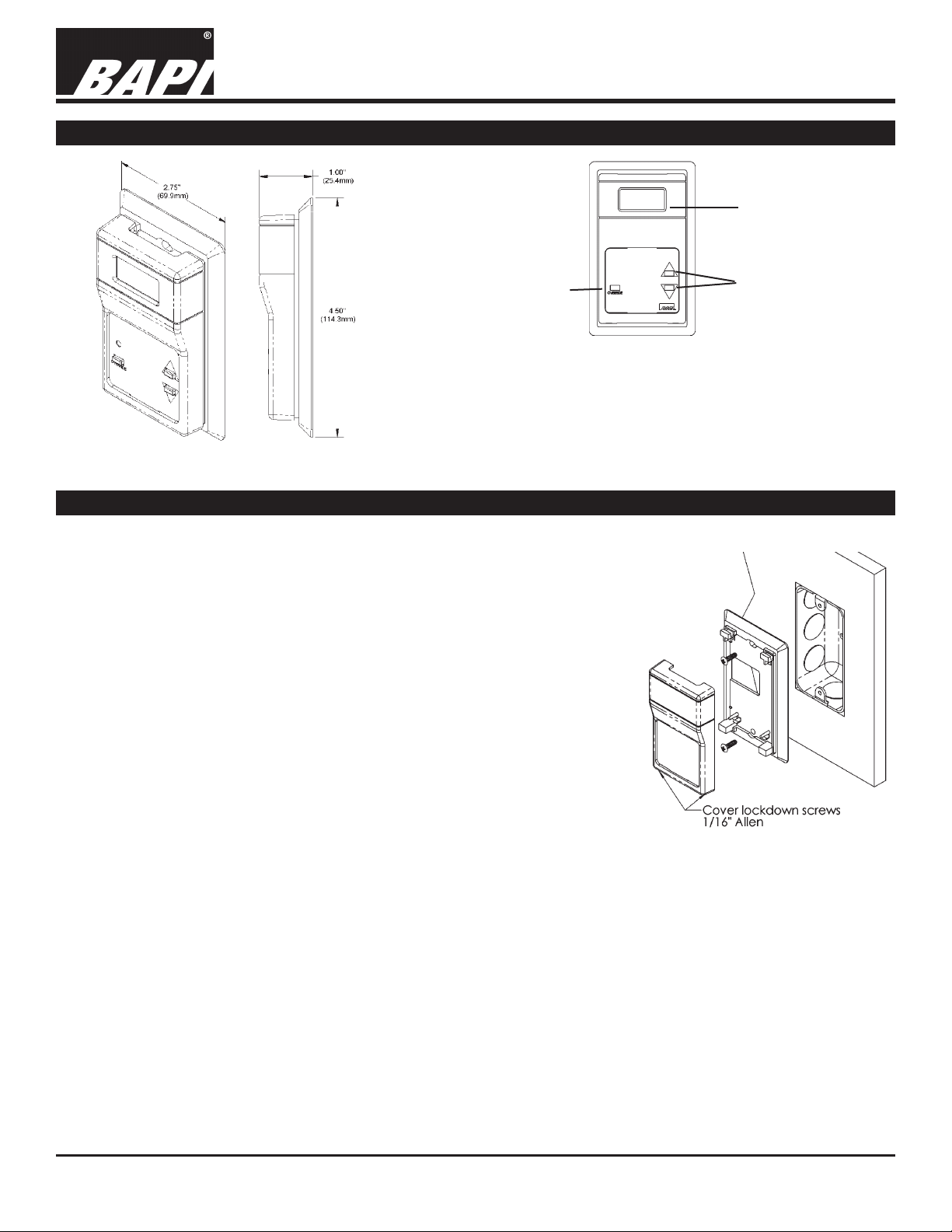
Product Identication
Front Panel
Description
Occupant
Override
Setpoint
When the setpoint buttons are pressed “UP” or “DOWN”, the
current setpoint will display. As the buttons are pressed again, the
display will change with each press.
Override
Fig 1: RuP Room Sensor
Mounting
Mounting hardware is provided for both junction box and drywall installation (junction box installation shown).
For Override, momentarily press the Override button.
Liquid Crystal
Display Readout
Setpoint Adjust
rev. 06/26/15
JUNCTION BOX
1. Pull wire through the wall and out of the junction box, leaving about 6 inches
free.
2. Pull the wire through the hole in the base plate.
3. Secure the plate to the box using the #6-32 x 1/2” mounting screws provided.
4. Terminate the unit according to the Termination Guidelines section.
5. Attach Cover by latching it to the top of the base, rotating the cover down and
snapping it into place.
6. Secure the cover by backing out the lock-down screws using a 1/16” allen
wrench until they are ush with the bottom of the cover.
DRYWALL MOUNTING
1. Place the base plate against the wall where you want to mount the sensor.
2. Use a pencil to mark the two mounting holes and the area where the wires will
come through the wall.
3. Drill two 3/16” holes in the center of each marked mounting hole. Insert a drywall anchor into each hole.
4. Drill one 1/2” hole in the middle of the marked wiring area.
5. Pull the wire through the wall and out of 1/2” hole, leaving about 6” free.
6. Pull the wire through the hole in the base plate.
7. Secure the base to the drywall anchors using the #6 x 1 inch mounting screws provided.
8. Terminate the unit according to the Termination Guidelines section.
9. Attach cover by latching it to the top of the base, rotating the cover down and snapping it into place. Secure the
cover by backing out the lock-down screws using a 1/16” Allen wrench until they are ush with the bottom of the
cover.
Fig 2: Junction box mounting
NOTE: In a wall-mount application, the wall temperature and the temperature of the air within the wall cavity can cause
erroneous readings. The mixing of room air and air from within the wall cavity can lead to condensation, erroneous
readings and premature failure of the sensor. To prevent these conditions, seal the conduit leading to the junction box
and use BAPI’s adhesive backed, foam insulating pad centered over the hole (order part number BA/FOAMBACK).
Specications subject to change without notice.
1
Page 2
RµP Style Room Units (BA/RuP)
Installation and Operation Instructions
9556_ins_rupa_gen
rev. 06/26/15
Termination
BAPI recommends using twisted pair of at least 22AWG and sealant lled connectors for all wire connections. Larger
gauge wire may be required for long runs. All wiring must comply with the National Electric Code (NEC) and local codes.
Do NOT run this device’s wiring in the same conduit as AC power wiring of NEC class 1, NEC class 2, NEC class 3 or
with wiring used to supply highly inductive loads such as motors, contactors and relays. BAPI’s tests show that uctuating and inaccurate signal levels are possible when AC power wiring is present in the same conduit as the signal lines. If
you are experiencing any of these difculties, please contact your BAPI representative
BAPI recommends wiring the product with power disconnected. Proper supply voltage, polarity, and
wiring connections are important to a successful installation. Not observing these recommendations may
damage the product and will void the warranty.
ALL RUP UNITS
Terminal Function
POWER 5 VDC (only if 5 VDC option is selected when ordered)
7 to 35 VDC (15 to 24 VDC recommended)
12 to 30 VAC (requires a separate pair of shielded wires)
GND To Controller GND, GROUND or Common terminal
LED –
SHLD External sensor cable shield (Not used in this
Lights Occupancy LED when shorted to ground. To
Controller Digital Output
configuration)
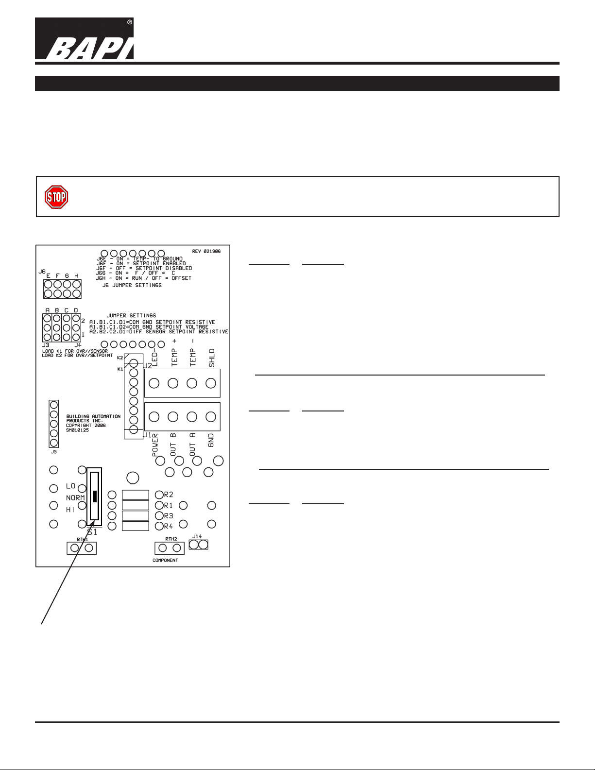
Fig 3: RµP Circuit Board
Shown with optional
T&B Switch (S1)
COMMON GROUND UNITS ONLY
Terminal Function
OUT A Setpoint (Resistive or Voltage Output). To Controller
Analog Input
OUT B
Temperature Sensor Output (Resistive Output). To
Controller Analog Input
DIFFERENTIAL GROUND UNITS ONLY
Terminal Function
TEMP + Temperature Sensor Output. To Controller Analog Input
TEMP – Temperature Sensor Output. To Controller Analog Input
OUT A Setpoint (Resistive Output). To Controller Analog Input
OUT B Setpoint (Resistive Output). To Controller Analog Input
NOTES
For Common Ground (CG) units, the GND (Common) terminal is
common beween the POWER, OUT A, and OUT B.
For Differential Ground (DF) units, OUT A and OUT B are the Setpoint Outputs, and TEMP + and TEMP – are the Thermistor or RTD
sensor outputs.
Specications subject to change without notice.
2
Page 3

RµP Style Room Units (BA/RuP)
C11 Wiring
C35 Wiring
Offset Temperature - Use
UP/DOWN arrows to set
Installation and Operation Instructions
9556_ins_rupa_gen
Factory Set J3, J4 & J6 Jumper Block Settings (for reference only)
Jumper Block J3 and J4 Settings -
Fig 4:
Common Ground with
Common Ground with
Resistive Setpoint
Note: Incorrect J3, J4 Jumper Settings can damage the sensor.
Optional Communications Jack in Base
Ground Black
Tip White
Ring Red
Note: Male
Jack shown
for clarity
Fig 5:
0 to 5VDC Setpoint
Wire Color
Fig 6:
Differential Ground with
Resistive Setpoint
Fig. 8: Front View
of Base with C35
Comm Jack
Jumper Block J6 Settings
Jumper Block J6 Settings (For Reference Only)
Jumper Pin Jumper Function
J6E
J6F
J6G
J6H
Front
View
ON "TEMP -" to Ground
OFF Differential Ground
ON Setpoint Enabled
OFF Setpoint Disabled
ON Fahrenheit
OFF Celsius
ON Normal Operation
OFF
Back
View
rev. 06/26/15
Fig. 7: C35 Comm Jack
C11 or C22 Wiring
Comm Jack Pin Wire Color
1 Not Connected
2 Black
3 Red
4 Yellow
5 White
6 Not Connected
C11 or C22
Comm Jack
Optional Test & Balance Switch - S1
LO: Sets the sensor value to
LOW temperature
NORM: Temperature Sensor
operates Normally
HI: Sets the sensor value to
HIGH temperature
Fig. 10
Fig. 9: Front
View of Base
with C11 or
C22 Comm
Front
View
Back
View
Jack
Sensor Type
1000W RTD 1.02KW (41.2°F) 1.15KW (101.5°F)
3000W Thermistor 7.87KW (39.5°F) 1.5KW (106.8°F)
10K-2W Thermistor 30.1KW (34.9°F) 4.75KW (109.2°F)
10K-3W Thermistor 26.7KW (35.9°F) 5.11KW (108.4°F)
10K-3(11K)W Thermistor 7.32KW (43.7°F) 3.65KW (105.2°F)
Low Resistance
(Temp)
High Resistance
(Temp)
Specications subject to change without notice.
3
Page 4

RµP Style Room Units (BA/RuP)
Installation and Operation Instructions
9556_ins_rupa_gen
rev. 06/26/15
Temperature, Setpoint and Occupancy Override LED Diagnostics
If the RuP doesn’t work upon installation, no LCD and no Output from terminals OUTA and/or OUTB. Check that the correct power is being supplied to the RuP by measuring the DC voltage between terminals POWER and GND. Also check
to see that the RuP is wired with the proper polarity, terminal GND as common and terminal POWER as V+. V+ should
be within the range of 7 to 35VDC, 12 to 30 VAC or optional 5 Volt and supply a minimum of 10mA for each RuP. If the
RuP’s LCD is working but there’s still no output from terminal OUTA or OUTB. Power down the Rup and remove the output wire(s) from the suspect terminal pin(s). Apply power and use a meter to measure the ohms (or voltage) output of the
terminal pin in question, as described in the three sections below.
TEMPERATURE OUTPUT
Determine that the temperature sensor’s wires are connected to the correct controller input terminals and are not loose.
Check the wires at the sensor and controller for proper connections. Measure the physical temperature at the temperature
sensor’s location using an accurate temperature standard. Disconnect the temperature sensor wire (SEN1) and measure
the temperature sensor’s resistance across the sensor output pins with an ohmmeter. Put the ohmmeters black lead on
Ground (GND) for common ground units or put the black lead on SEN2 for differential ground units and the red lead on
SEN1. Compare the temperature sensor’s resistance to the appropriate temperature sensor table on the BAPI web site.
If the measured resistance is different from the temperature table by more than 5% call BAPI technical support. Find
BAPI’s web site at www.bapihvac.com; click on the button labeled SENSORS on the left of the screen and then click on
the type of sensor you have. Don’t forget to reconnect the wires. Make sure that the test and balance switch is in the correct position. Make sure that the temperature sensor element leads are not touching one another.
SETPOINT OUTPUT
The setpoint output may be measured on CG (common ground) units between terminals OUTA
output is measured on DF (differential input) units between terminal OUTA and OUTB. To test the setpoint output, rst remove any wires from the setpoint output terminals, apply power to the RuP and measure the setpoint output. Compare the
measured reading to the setpoint information printed on the RuP’s label. The temperature setpoint value will be displayed
on the RuP’s LCD.
and GND. The setpoint
LED INDICATOR
The LED is internally connected to the RuP’s 5 Volt supply and can be turned on by connecting the terminal LED- to the
RuP’s GND terminal. Most often this is done through a dry contact at the controller. To test the LED, rst remove any wires
from the LED- terminal, apply power to the RuP and then use a short piece of wire to short between the LED- and GND
terminals. Observe the LED operation from the front of the RuP. Power down the RuP and reconnect the output(s) to the
controller. If the output(s) still are non-functional, remove power and check the controller’s input conguration.
Communications Jack Diagnostics
PROBLEMS:
No connection to controller can be made
Information received through wires is garbled
POSSIBLE SOLUTIONS:
- Conrm connection from patch cable to remote computer
- Check wiring for proper termination
- Check wiring for proper termination
- Verify that no wires are shorted together
Specications
Power: 5 VDC (only if 5 VDC option is selected when ordered)
7 to 35 VDC (15 to 24 VDC recommended)
12 to 30 VAC (requires a separate pair of shielded wires)
Power Consumption: 10 mA max. DC, .2 VA maximum AC
Sensing Element: Thermistor, RTD or Semiconductor
Wiring: 2 to 4 pair of 16 to 22AWG*
Comm. Jack: Optional 3.5 mm Phono Jack, RJ11 or RJ22 Jacks
Mounting: Standard 2” by 4” J-box or drywall
mount (mounting screws provided)
Environmental Operation Range:
Temperature: 32 to 122
o
F (0 to 50 oC)
Humidity: 0 to 95%, non-condensing
Enclosure Material & Rating: ABS Plastic, UL94 HB
Specications subject to change without notice.
4
 Loading...