

Page 1
RµPS Style Room Units (BA/RuPS)
Installation & Operating Instructions
10097_ins_rups
Product Identication and Overview
The RµPS room temperature sensor comes in a Delta Style Enclosure
with Display, Setpoint Adjustment and Occupancy Override. The Setpoint
Adjust is a vertical slidepot which provides an analog output and comes
with a Warm/Cool legend imprinted on the unit’s base (Other setpoint
legends are available).
Setpoint values are transmitted as resistive or voltage values for easy
conguration with the controller. The Occupancy Override signal is
available as a direct output or in parallel with the Sensor or Setpoint, or
as a separate output. An optional 3.5mm (1/8”) or RJ11 communication
jack can be mounted in the base to provide direct access to the network.
The sensor and setpoint outputs can be congured for “common ground”
or “differential” controller inputs.
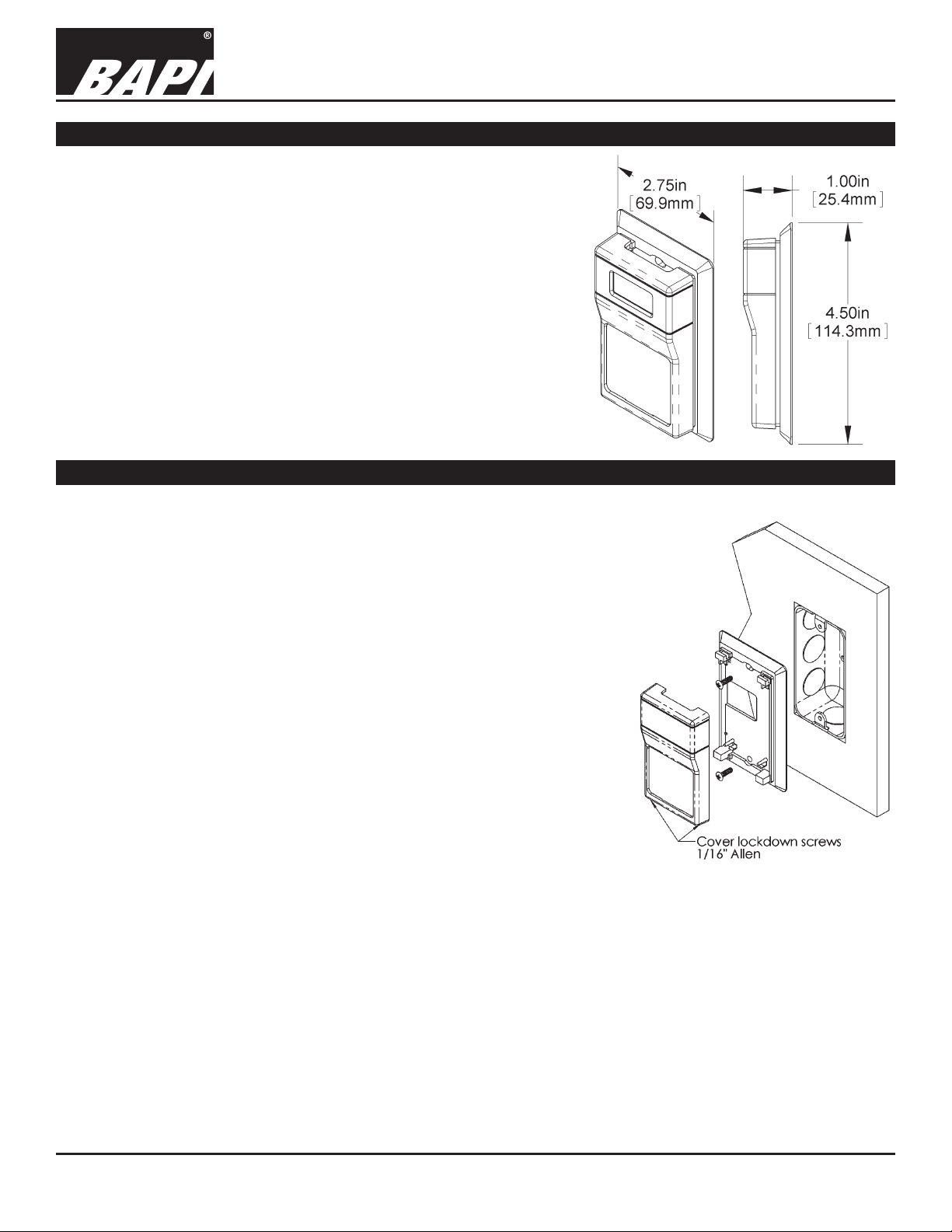
Fig 1: RuPS Dimensions
Mounting
Mounting hardware is provided for both junction box and drywall installation (junction box installation shown).
JUNCTION BOX
1. Pull the wire through the wall and out of the junction box, leaving about six
inches free.
2. Pull the wire through the hole in the base plate.
3. Secure the plate to the box using the #6-32 x 1/2” mounting screws provided.
4. Terminate the unit according to the guidelines in the Termination section.
5. Attach Cover by latching it to the top of the base, rotating the cover down and
snapping it into place.
6. Secure the cover by backing out the lock-down screws using a 1/16” Allen
wrench until they are ush with the bottom of the cover.
rev. 06/26/15
DRYWALL MOUNTING
1. Place the base plate against the wall where you want to mount the sensor.
2. Use a pencil to mark the two mounting holes and the area where the wires
will come through the wall.
3. Drill two 3/16” holes in the center of each marked mounting hole. Insert a
drywall anchor into each hole.
4. Drill one 1/2” hole in the middle of the marked wiring area. Pull the wire
through the wall and out the 1/2” hole, leaving about 6 inches free.
5. Pull the wire through the hole in the base plate.
6. Secure the base to the drywall anchors using the #6 x 1 inch mounting screws provided.
7. Terminate the unit according to the guidelines in the Termination Section.
8. Attach cover by latching it to the top of the base, rotating the cover down and snapping it into place.
9. Secure the cover by backing out the lock-down screws using a 1/16” Allen wrench until they are ush with the bottom
of the cover.
NOTE: In a wall-mount application, the wall temperature and the temperature of the air within the wall cavity can cause
erroneous readings. The mixing of room air and air from within the wall cavity can lead to condensation, erroneous
readings and premature failure of the sensor. To prevent these conditions, seal the conduit leading to the junction box and
use BAPI’s adhesive backed, foam insulating pad centered over the hole (order part number BA/FOAMBACK).
Specications subject to change without notice.
Fig. 2: Mounting to a Junction Box
1
Page 2
RµPS Style Room Units (BA/RuPS)
Installation & Operating Instructions
10097_ins_rups
rev. 06/26/15
Terminations
BAPI recommends using twisted pair of at least 22AWG and sealant lled connectors for all wire connections.
Larger gauge wire may be required for long runs. All wiring must comply with the National Electric Code (NEC) and
local codes.
Do NOT run this device’s wiring in the same conduit as AC power wiring of NEC class 1, NEC class 2, NEC class 3
or with wiring used to supply highly inductive loads such as motors, contactors and relays. BAPI’s tests show that
uctuating and inaccurate signal levels are possible when AC power wiring is present in the same conduit as the
signal lines. If you are experiencing any of these difculties, please contact your BAPI representative.
BAPI recommends wiring the product with power disconnected. Proper supply voltage, polarity, and
wiring connections are important to a successful installation. Not observing these recommendations may
damage the product and will void the warranty.
ALL RUPS UNITS
Power 5 VDC (only if 5 VDC option is selected when ordered)
9 to 40 VDC (15 to 24 VDC recommended)
15 to 28 VAC (requires a separate pair of shielded wires)
GND To Controller GND, GROUND or Common terminal
LED1 Lights Occupancy LED when shorted to ground.
To Controller Digital Output
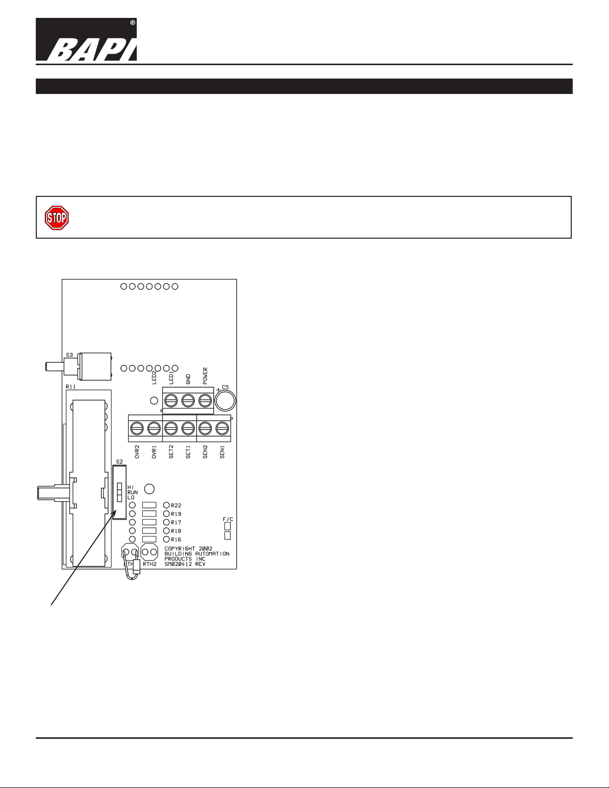
Fig 3: RuPS Circuit Board
Shown with optional T&B Switch (S2)
COMMON GROUND (CG) UNITS
SEN1 Thermistor/RTD Sensor Output. To Controller Analog Input.
SEN2 Internally Connected to GND
SET1 Temperature Setpoint Output. To Controller Analog Input.
SET2 Internally Connected to GND
OVR1 Pushbutton, dry contact output. To Controller Digital Input
OVR2 Internally Connected to GND
DIFFERENTIAL GROUND (DF) UNITS
SEN1 Thermistor/RTD Sensor Output. To Controller Analog Input.
SEN2 Thermistor/RTD Sensor Output. To Controller Analog Input.
SET1 Temperature Setpoint Output. To Controller Analog Input.
SET2 Temperature Setpoint Output. To Controller Analog Input.
OVR1 Pushbutton, dry contact output. To Controller Digital Input.
OVR2 Pushbutton, dry contact output. To Controller Digital Input.
Notes:
In Common Ground (CG) conguration, GND, SEN2, SET2 &
OVR2 are all internally connected.
In Differential Ground (DG) conguration: GND, SEN2, SET2 &
OVR2 are all internally isolated.
Specications subject to change without notice.
2
Page 3

RµPS Style Room Units (BA/RuPS)
Installation & Operating Instructions
10097_ins_rups
Optional Test & Balance Switch
Sensor Low High
Type Resistance (Temp) Resistance (Temp)
1000Ω RTD 1.02KΩ (41.2°F) 1.15KΩ (101.5°F)
3000Ω Thermistor 7.87KΩ (39.5°F) 1.5KΩ (106.8°F)
10K-2Ω Thermistor 30.1KΩ (34.9°F) 4.75KΩ (109.2°F)
10K-3Ω Thermistor 26.7KΩ (35.9°F) 5.11KΩ (108.4°F)
10K-3(11K)Ω Thermistor 7.32KΩ (43.7°F) 3.65KΩ (105.2°F)
Optional Communications Jack
Fig. 4:
C35 Comm Jack
(Male Jack shown for clarity)
rev. 06/26/15
Optional Test and Balance Switch (S2)
HI: Will set the sensor value to High temp
RUN: Temperature sensor will operate Normally
LO: Will set the sensor value to Low temp
Fig. 5:
C35 Comm Jack
in Unit’s Base.
(Front of unit base
is shown at left,
back of base at
right)
C11 or C22 Wiring
Fig. 7:
C11 or C22 Comm
Jack in Unit’s
Base.
(Front of unit base
is shown at left,
back of base at
Fig. 6:
right)
C11 or C22 Comm Jack
Temperature Display Offset
1. Power sensor
2. Remove sensor from the wall plate
3. Short the F/C pads on lower right of the printed circuit board for more than 10 seconds
4. The display will show 00
5. The display will cycle from 00 to 03 to -03 and back to 00.
6. When the offset you need is displayed, short the F/C pads for about 1 second.
7. The offset you entered will be placed into non-volatile memory and be held through power cycles.
8. If you do not program an offset, the sensor will go back to normal operation without change after 18 seconds.
Changing From Fahrenheit to Celsius
1. Power sensor
2. Remove sensor from the wall plate
3. Short the F/C pads on lower right for less than 3 seconds
4. The display will cycle from F to C
5. When the temperature unit you want is showing, short the F/C pads for about 1 second
6. The temperature unit you entered will be placed into non-volatile memory and be held through power cycles.
7. If you do not program a temperature unit, the sensor will go back to normal operation without change after 10 seconds.
Specications subject to change without notice.
3
Page 4

RµPS Style Room Units (BA/RuPS)
Installation & Operating Instructions
10097_ins_rups
Diagnostics
Possible Problems:
General troubleshooting
Temperature reading is
incorrect
rev. 06/26/15
Possible Solutions:
- Verify that the input is set up correctly in the controller and building automation software.
- Check wiring at the sensor and controller for proper connections.
- Check for corrosion at either the controller or the sensor. Clean off the corrosion, restrip the interconnecting wire and reapply the connection. In extreme cases, replace the
controller, interconnecting wire and/or sensor.
- Label the terminals that the interconnecting wires are connected to at the sensor end
and the controller end. Disconnect the interconnecting wires from the controller and the
sensor. With the interconnecting wires separated at both ends measure the resistance
from wire-to-wire with a multimeter. The meter should read greater than 10 Meg-ohms,
open or OL depending on the meter you have. Short the interconnecting wires together
at one end. Go to the other end and measure the resistance from wire-to-wire with a
multimeter. The meter should read less than 10 ohms (22 gauge or larger, 250 feet or
less). If either test fails, replace the wire.
- Verify that the temperature sensor’s wires are connected to the correct controller input
terminals and are not loose.
- Check the wires at the sensor and controller for proper connections.
- Measure the physical temperature at the temperature sensor’s location using an accurate
temperature standard. Disconnect the temperature sensor wire (SEN1) and measure the
temperature sensor’s resistance across the sensor output pins with an ohmmeter. Put the
ohmmeters black lead on Ground (GND) for common ground units or put the black lead
on SEN2 for differential ground units and the red lead on SEN1. Compare the temperature
sensor’s resistance to the appropriate temperature sensor table on the BAPI web site.
If the measured resistance is different from the temperature table by more than 5% call
BAPI technical support. Find BAPI’s web site at www.bapihvac.com; click on the button
labeled SENSORS on the left of the screen and then click on the type of sensor you have.
Don’t forget to reconnect the wires.
- Make sure that the test and balance switch is in the correct position.
- Make sure that the temperature sensor element leads are not touching one another.
Setpoint reading is
incorrect
Override is not working
correctly
- Make sure that the setpoint output is correct. Remove the setpoint output wire (SET1) and
check the output for the correct resistance or voltage output. Put the meters black lead
on Ground (GND) for common ground units or put the black lead on SET2 for differential
ground units and the red meter lead on SET1. See the product label for your specic
range. Don’t forget to reconnect the wire.
- Check that the resistance across the override output is less than 5 ohms when the
OVERRIDE button is pushed. Disconnect the override wire (OVR1). Put the ohmmeters
black lead on Ground (GND) for common ground units or put the black lead on OVR2 for
differential ground units and put the red lead on OVR1. Don’t forget to reconnect the wire.
Specications
Power:
5 VDC (only if 5 VDC option is selected when ordered)
9 to 40 VDC (15 to 24 VDC recommended)
15 to 28 VAC (Requires a separate pair of shielded wires)
Power Consumption: 10 mA max DC, .2 VA max AC
Sensing Element: Thermistor, RTD or Semiconductor
Wiring: 2 to 5 pair of 16 to 22AWG
Specications subject to change without notice.
Comm. Jacks:
Mounting:
(screws provided)
Environmental Operation Range:
Temperature: 32 to 122 oF (0 to 50 oC)
Humidity: 0 to 95%, non-condensing
Enclosure Material & Rating: ABS Plastic, UL94 HB
Opt. 3.5mm Phono Jack, RJ11 or RJ22 Jacks
Standard 2” by 4” J-box or drywall mount
4
 Loading...