

Page 1
PreCon Style Room Units with Thermistor, RTD or
Semiconductor Sensor (BA/-RSZ)
Termination and Troubleshooting
9546_ins_temp_rsz+
Product Identication
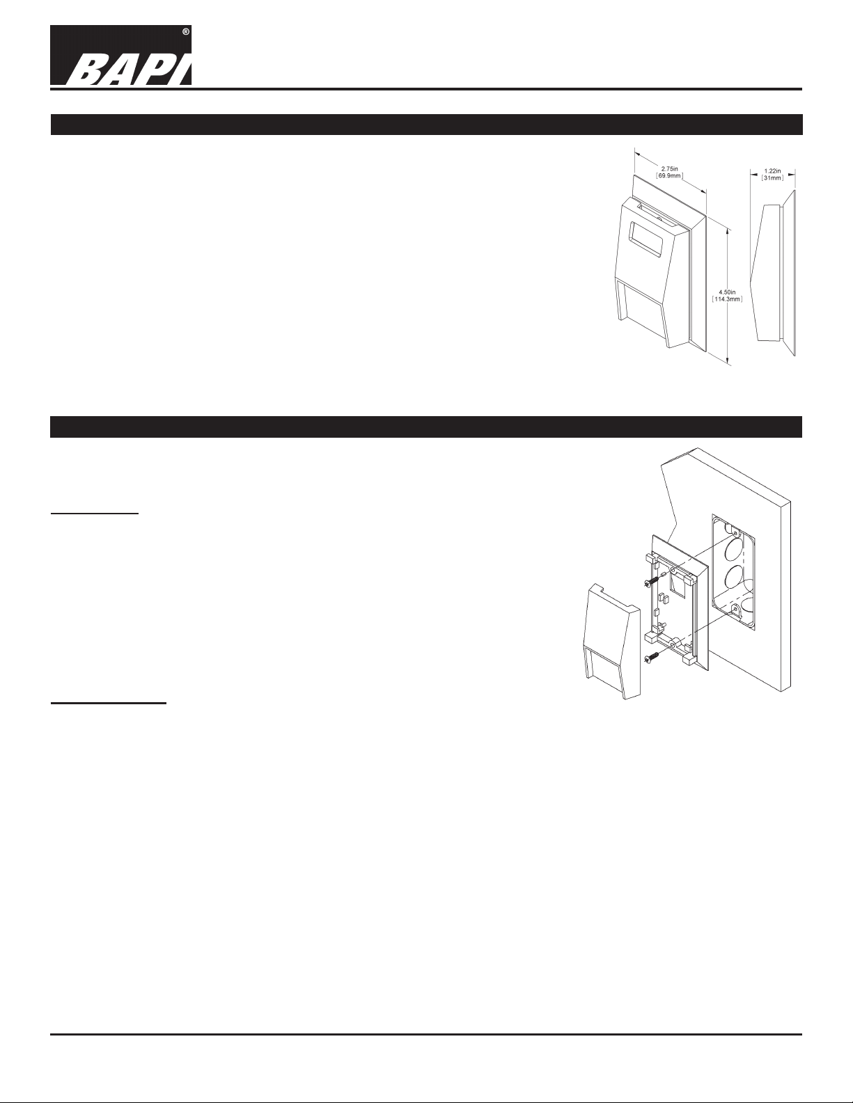
The PreCon Style Room Sensor is available as a temperature sensor alone or as a “+”
version with Setpoint, Override, Communications Jack and LED. An optiona Bi-Metal
Indicator is available for both versions.
Setpoint
A 3-position switch allows limited control over the zone’s setpoint. In the center position,
the Setpoint is at the system default. If the switch is moved to the left or right, the
Setpoint is decreased or increased by a system dened amount.
Override
Allows the occupant to extend the zone occupancy schedule by a system determined
amount. Each time the switch is moved to the side, the controller will register an
occupancy override. The closed switch then springs back to the normally open position.
Communication Jack
The “+” unit includes a 5-pin Comm Jack.
LED
The “+” unit includes an LED that can be lit with 5VDC from the BAS system.
Mounting
rev. 06/26/15
Fig. 1: PreCon Style Room
Sensor
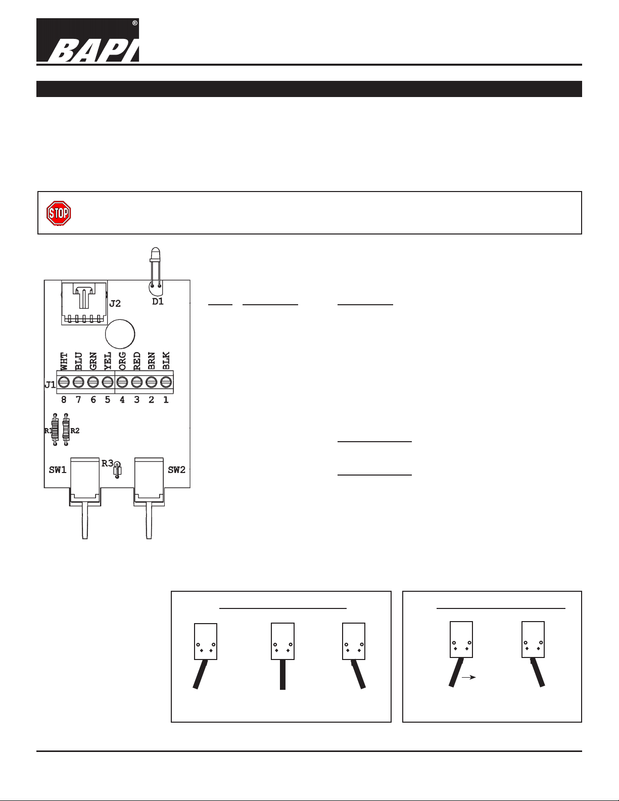
Mounting hardware is provided for both junction box and drywall installation (junction
box installation shown).
Junction Box
1. Pull the wire through the wall and out of the junction box, leaving about six
inches free.
2. Pull the wire through the hole in the base plate.
3. Secure the plate to the box using the #6-32 x 1/2 inch mounting screw provided.
4. Terminate the unit according to the guidelines in Termination on page 1.
5. Attach Cover by latching it to the top of the base, rotating the cover down and
snapping it into place.
6. Secure the cover by backing out the lock-down screws using a 1/16” allen
wrench until they are ush with the bottom of the cover.
Drywall Mounting
1. Place the base plate against the wall where you want to mount the sensor.
2. Using a pencil mark out the two mounting holes and the area where the wires
will come through the wall.
3. Drill two 3/16” holes in the center of each marked mounting hole. Insert a drywall anchor into each hole.
4. Drill one 1/2” hole in the middle of the marked wiring area.
5. Pull the wire through the wall and out of the 1/2” hole, leaving about six inches free.
6. Pull the wire through the hole in the base plate.
7. Secure the base to the drywall anchors using the #6 x 1 inch mounting screws provided.
8. Terminate the unit according to the guidelines in Termination on page 1.
9. Attach cover by latching it to the top of the base, rotating the cover down and snapping it into place.
10. Secure the cover by backing out the lock-down screws using a 1/16” allen wrench until they are ush with the bottom
of the cover.
Fig. 2: PreCon Style J-Box Mounting
NOTE: In a wall-mount application, the wall temperature and the temperature of the air within the wall cavity can cause er-
roneous readings. The mixing of room air and air from within the wall cavity can lead to condensation, erroneous readings
and premature failure of the sensor. To prevent these conditions, seal the conduit leading to the junction box and seal the
hole in the drywall by using an adhesive backed, foam insulating pad(order part number BA/FOAMBACK).
Specications subject to change without notice.
1 of 4
Page 2
PreCon Style Room Units with Thermistor, RTD or
Semiconductor Sensor (BA/-RSZ)
Termination and Troubleshooting
9546_ins_temp_rsz+
Termination
BAPI recommends using twisted pair of at least 22AWG and sealant lled connectors for all wire connections. Larger
gauge wire may be required for long runs. All wiring must comply with the National Electric Code (NEC) and local codes.
Do NOT run this device’s wiring in the same conduit as AC power wiring of NEC class 1, NEC class 2, NEC class 3 or with
wiring used to supply highly inductive loads such as motors, contactors and relays. BAPI’s tests show that uctuating and
inaccurate signal levels are possible when AC power wiring is present in the same conduit as the signal lines. If you are
experiencing any of these difculties, please contact your BAPI representative.
BAPI recommends wiring the product with power disconnected. Proper supply voltage, polarity, and
wiring connections are important to a successful installation. Not observing these recommendations may
damage the product and will void the warranty.
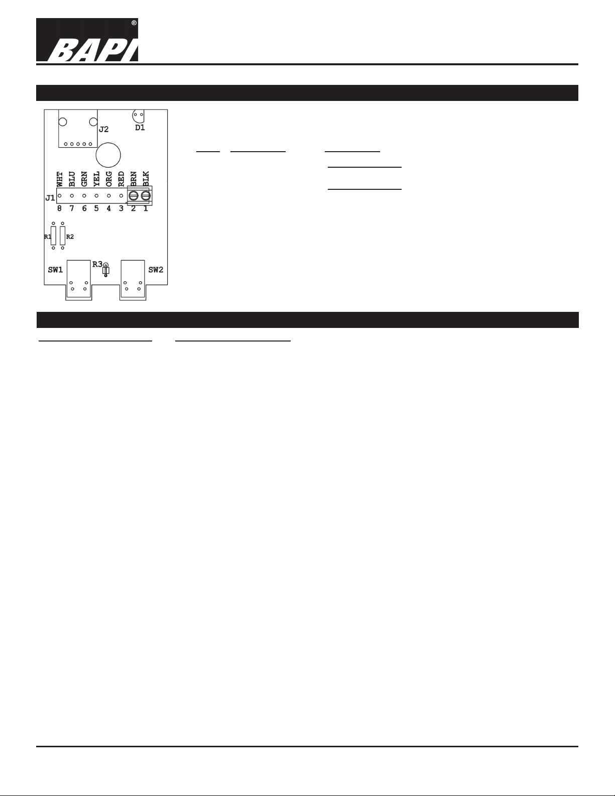
RSZ+ Units with Setpoint, Override and Communications Jack
Pin # Description Connection
8 Comm Jack Pin 4 Connected from terminal block thru Comm. Jack
rev. 06/26/15
Fig. 3: PreCon RSZ+
Unit Circuit Board
7 Comm Jack Pin 3 Connected from terminal block thru Comm. Jack
LED (+) Anode Connected to +5VDC to power LED
6 Comm Jack Pin 2 Connected from terminal block thru Comm. Jack
5 Comm Jack Pin 1 Connected from terminal block thru Comm. Jack
4 LED (-) Cathode To GND (Common) of Controller thru a 1KΩ Resistor
3 Setpoint & Override Resistive Output - To Analog Input of controller.
(Reference to ground)
2 Sensor Resistive Output - To Analog Input of controller.
(Reference to ground)
1 GND (Common) To GND or Common of controller
(Connected internally to Comm Jack Pin 5)
Setpoint Switch 1 (SW1)
Override Switch 2 (SW2)
Setpoint
= 10K ohms
Normally
Open Position
Specications subject to change without notice.
Setpoint
= 20K ohms
Spring
Return
Override Position =
Momentary Short
Normally
Open Position
2 of 4
Page 3
9546_ins_temp_rsz+
Termination continued...
PreCon Style Room Units with Thermistor, RTD or
Semiconductor Sensor (BA/-RSZ)
Termination and Troubleshooting
rev. 06/26/15
RSZ Units without Setpoint, Override or Communications Jack
Pin # Description Connection
2 Sensor (Resistive Output - To Analog Input of controller)
1 Sensor (Resistive Output - To Analog Input of controller)
Fig. 4: PreCon RSZ
Unit Circuit Board
Diagnostics
POSSIBLE PROBLEMS:
General troubleshooting
Temperature reading is
incorrect
POSSIBLE SOLUTIONS:
- Determine that the input is set up correctly in the controller software and building
automation software.
- Check wiring for proper termination
- Check for corrosion at either the controller or the sensor. Clean off the corrosion, restrip the interconnecting wire and reapply the connection. In extreme cases, replace the
controller, interconnecting wire and/or sensor.
- Label the terminals that the interconnecting wires are connected to at the sensor end
and the controller end. Disconnect the interconnecting wires from the controller and the
sensor. With the interconnecting wires separated at both ends measure the resistance
from wire-to-wire with a multimeter. The meter should read greater than 10 Meg-ohms,
open or OL depending on the meter you have. Short the interconnecting wires together
at one end. Go to the other end and measure the resistance from wire-to-wire with a
multimeter. The meter should read less than 10 ohms (22 gauge or larger, 250 feet or
less). If either test fails, replace the wire.
- Determine that the temperature sensors wires are connected to the correct controller
input terminals and are not loose.
- Check the wires at the sensor for proper connections.
- Measure the physical temperature at the temperature sensor’s location using an
accurate temperature standard. Disconnect the temperature sensor wires and
measure the temperature sensor’s resistance across the sensor output pins with an
ohmmeter. Compare the temperature sensor’s resistance to the appropriate temperature
sensor table on the BAPI website. If the measured resistance is different from the
temperature table by more than 5% call BAPI technical support. Find BAPI’s website at
www.bapihvac.com; click on “Resource Library” and “Sensor Specs” then click on the
type of sensor you have. Don’t forget to reconnect the wires.
- Make sure that the sensor leads are not touching one another.
- Determine if the sensor is exposed to an external air source different from room
environment, such as a conduit draft. If so, ll the junction box with berglass insulation
or plug the conduit.
Specications subject to change without notice.
3 of 4
Page 4

PreCon Style Room Units with Thermistor, RTD or
Semiconductor Sensor (BA/-RSZ)
Termination and Troubleshooting
9546_ins_temp_rsz+
Additional Diagnostics for RSZ+ Units with Setpoint, Override and Communications Jack
rev. 06/26/15
Problems:
Setpoint is not working correctly
Override is not working correctly
Possible Solutions:
- Check if “SW1” is installed
- Determine if the “Setpoint” output is 10K ohms from Pin 1 to Pin 3 when
SW1 is in the correct position, see Page 2
- Determine if the “Setpoint” output is 20K ohms from Pin 1 to Pin 3 when
SW1 is in the correct position, see Page 2
- Check wiring for proper termination
- Check if “SW1” is installed
- Determine if the output from Pin 1 to Pin 3 is less than 50 ohms when
“SW1” is used
- Check wiring for proper termination
Specications
Environmental Operation Range:
Temperature: 32 to 122 oF (0 to 50 oC)
Humidity: 0 to 95%, non-condensing
Material: ABS Plastic
Material Rating: UL 94, HB
Agency: CE Compliant (
All Passive Thermistors 10KΩ and smaller are CE compliant.)
Specications subject to change without notice.
4 of 4
 Loading...