

Page 1
Outside Air (OSA) Temperature Transmitters
BA/T1# -O Temperature Sensor
Installation & Operations
20920_ins_OSA_Active
Overview
The BA/T1xx-O is for Outside Air mounting and temperature measurement. The probe is made to protect the sensor from
impediments such as, rain, sleet, snow or bird droppings. The 4 to 20mA transmitter can be ordered with 100Ω (385),
1KΩ (385) RTDs or 10KΩ type 2 thermistor sensors. A 0 to 5VDC or 0 to 10VDC transmitter is also available with a 10KΩ
type 2 thermistor sensor. Special high accuracy RTD matched transmitters (M) are available which use class A RTD’s and
match the sensor to the transmitter for improved accuracy. Enclosure mounting styles come in plastic or metal for both
NEMA 3R and NEMA 4 applications and are all UV rated.
Identication
rev. 06/30/15
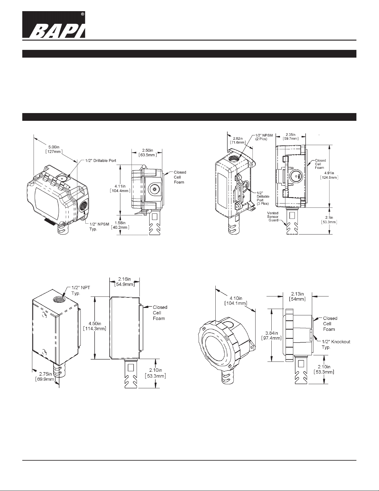
Fig 1: Outside Air Sensor in a BAPI-Box (BB) Enclosure
Fig 3: Outside Air Sensor in a Weatherproof (WP) Enclosure
Fig 2: Outside Air Sensor in a BAPI-Box 2 (BB2) Enclosure
Fig 4: Outside Air Sensor in a Weather Tight (EU) Enclosure
Specications subject to change without notice.
1 of 3
Page 2
20920_ins_OSA_Active
Mounting
Outside Air (OSA) Temperature Transmitters
BA/T1# -O Temperature Sensor
Installation & Operations
rev. 06/30/15
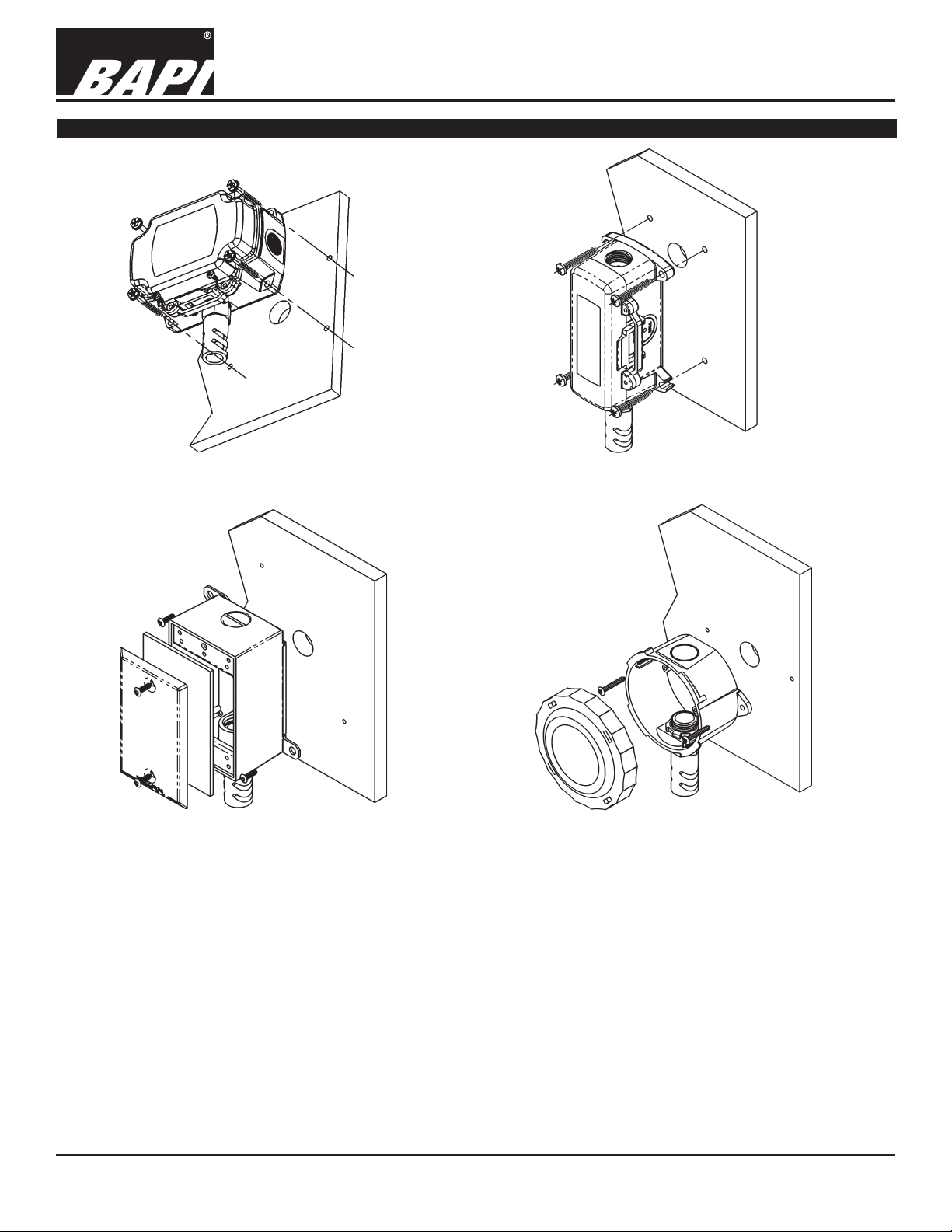
Fig 5: BAPI-Box (BB) Enclosure Installation
Fig 6: BAPI-Box 2
Fig 8: Weather Tight (EU) Enclosure InstallationFig 7: Weatherproof (WP) Enclosure Installation
(BB2) Enclosure Installation
Outside Air (OSA) sensor placement is critical to good performance. The OSA sensor must be mounted in the shade
away from building windows, doors or vents. They should never be in direct sunlight or you will have higher than expected temperature readings by as much as +30%. The ideal shaded location in the Northern hemisphere is on the North side
of the building. In the Southern hemisphere the South side of the building is ideal.
The sensor shield and probe should always point down and mounted between four feet above the ground/roof and one
foot minimum below the eave. (Note: Four feet keeps the sensor above the ground or roof top radiation and one foot under the eave prevents measurement of trapped heat from under the eave.)
Drill the mounting holes and mount as shown in the gures 5-8. Snug up the mounting screws to ensure that the foam
backing compresses to about 50% of its thickness to make a gasket type seal against the wall surface.
Route the wires into the box and terminate with sealant lled connectors to prevent water from attacking the connection,
thereby preventing costly callbacks. Best practice is to caulk the wiring hole after the wiring is installed. Close the cover of
the BB, BB2 or WP boxes and secure with provided cover screws or twist on the cover of the EU box to the second click.
Specications subject to change without notice.
2 of 3
Page 3
Outside Air (OSA) Temperature Transmitters
BA/T1# -O Temperature Sensor
Installation & Operations
20920_ins_OSA_Active
Wiring & Termination
BAPI recommends using twisted pair of at least 22AWG and sealant lled connectors for all wire connections. Larger
gauge wire may be required for long runs. All wiring must comply with the National Electric Code (NEC) and local codes.
Do NOT run this device’s wiring in the same conduit as high or low voltage AC power wiring. BAPI’s tests show that inaccurate signal levels are possible when AC power wiring is present in the same conduit as the sensor wires.
rev. 06/30/15
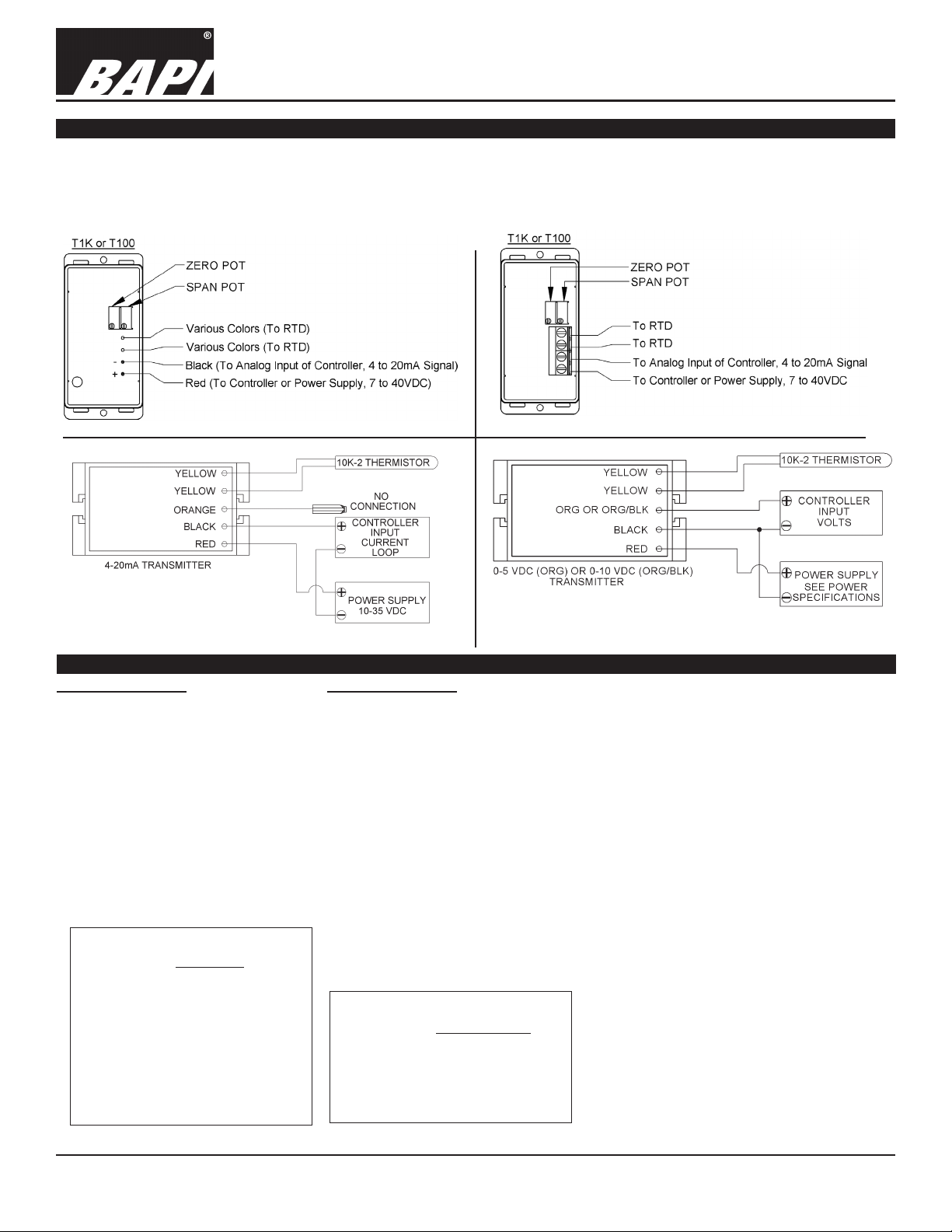
Fig. 10: Typical
RTD 4 to 20mA
Transmitter with
Terminals
Fig. 11: Typical Thermistor
4 to 20mA Transmitter
Fig. 9: Typical
RTD 4 to 20 mA
Transmitter with
Flying Leads
Fig. 12: Typical Thermistor
Voltage Transmitter
Diagnostics
Possible Problems: Possible Solutions:
•
Unit will not operate. - Measure the power supply voltage by placing a voltmeter across the transmitter’s (+) and
- Check if the RTD wires are physically open or shorted together and are terminated to the
- Measure the physical temperature at the temperature sensor’s location using an accurate
(-) terminal. Make sure that it matches the drawings above and power requirements in the
specications.
transmitter.
temperature standard. Disconnect the temperature sensor wires and measure the
temperature sensor’s resistance with an ohmmeter. Compare the temperature sensor’s
resistance to the appropriate temperature sensor table on the BAPI web site.
• The reading is incorrect in the controller.
- For a 4-20mA current transmitter measure the transmitter current by placing an ammeter
Voltage Temperature Equation
T = TLow + (V x TSpan)
VSpan
T = Temperature at sensor
TLow = Low temperature of span
THigh = High temperature of span
TSpan = THigh - TLow
VLow = Low transmitter voltage
usually=(0, 1 or 2v)
VHigh = High transmitter voltage
usually=(5 or 10v)
VSpan = VHigh - VLow
V = Signal reading in volts
- Determine if the input is set up correctly in the controllers and BAS software.
in series with the controller input. The current should read according to the “4-20mA
Temperature Equation” shown below.
- For a voltage transmitter, measure the signal with a volt meter (Orange or Orange/Black to
Black). The signal should read according to the “Voltage Temperature Equation” shown below.
4-20mA Temperature Equation
T = TLow + (A -4) x (TSpan)
16
T = Temperature at sensor
TLow = Low temperature of span
THigh = High temperature of span
TSpan = THigh - TLow
A = Signal reading in mA
Specications subject to change without notice.
3 of 3
Page 4

20920_ins_OSA_Active
Specications
Outside Air (OSA) Temperature Transmitters
BA/T1# -O Temperature Sensor
Installation & Operations
rev. 06/30/15
RTD Transmitter
Power Required: 7 to 40VDC
Transmitter Output: 4 to 20mA, 850Ω@24VDC
Output Wiring: 2 wire loop
Output Limits: <1mA (short), <22.35mA (open)
Span:
Zero:
Min. 30ºF (17ºC), Max 1000ºF, (555ºC)
Min. -148°F (-100°C), Max 900ºF (482ºC)
Zero & Span Adjust: 10% of span
Accuracy: ±0.065% of span
Linearity: ±0.125% of span
Power Output Shift: ±0.009% of span
RTD Sensor: 2 wire Platinum (Pt), 385 curve
Transmitter Ambient -4 to 158ºF(-20 to 70ºC)
0 to 95% RH, Non-condensing
Thermistor Transmitter
Supply Voltage:
10 to 35 VDC (0 to 5 VDC or 4 to 20 mA Outputs)
15 to 35 VDC (0 to 10 VDC Output)
12 to 24 VAC (0 to 5 VDC Outputs)
15 to 24 VAC (0 to 10 VDC Output)
Transmitter Output: 4 to 20mA, 700Ω@24VDC
0 to 5 & 0 to 10VDC, 10KΩ min
Output Wiring: 2 & 3 wire (See wiring detail on pg. 3)
Transmitter Limits: -40 to 185ºF, (-40 to 85ºC)
Accuracy: ±1.015ºC, from (0 to 65ºC)
Linearity: ±0.065ºC, from (0 to 65ºC)
Resolution: Span/1024
Thermistor Sensor: 10K-2 Thermistor, 10KΩ @77ºF
Transmitter Ambient: 32 to 158ºF, (0º to 70ºC)
0 to 95% RH, Noncondensing
Thermistor: 10K-2,Thermal Resistor (Bare Sensor)
Accuracy (Std): ±0.36ºF, (±0.2ºC)
Accuracy (High): ±0.18ºF, (±0.1ºC), [XP] option
Stability: < 0.036ºF/Year, (<0.02ºC/Year)
Heat Dissipation: 2.7 mW/ºC
Probe Range: -40º to 221ºF (-40º to 105ºC)
Wire Colors:
Standard: Yellow/Yellow (no polarity)
High Acc. [XP]: Yellow/Yellow (no polarity)
RTD:
Resistance Temp Device (Bare Sensor)
Platinum (Pt): 100Ω and 1KΩ @0ºC, 385 curve,
Pt Accuracy (Std): 0.12% @Ref, or ±0.55ºF, (±0.3ºC)
Pt Accuracy (High): 0.06% @Ref, or ±0.277ºF,
(±0.15ºC), [A]option
Pt Stability: ±0.25ºF, (±0.14ºC)
Pt Self Heating: 0.4 ºC/mW @0ºC
Pt Probe Range: -40º to 221ºF, (-40 to 105ºC)
Wire Colors:
General color code (other colors possible)
1KΩ, Class B Orange/Orange (no polarity)
1KΩ, Class A Orange/White (no polarity)
100Ω, Class B Red/Red (no polarity)
100Ω, Class A Red/Red-w/black stripe (no polarity)
Sensitivity: Approximate @ 32ºF (0ºC)
Thermistor Non-linier - (See www.bapihvac.com,
click “Sensor Specs”)
RTD (Pt): 3.85Ω/ºC for 1KΩ RTD
0.385Ω/ºC for 100Ω RTD
Lead Wire: 22awg stranded
Insulation: Etched Teon, Plenum rated
Probe: Vented polycarbonate shield, ½” OD
Probe Length:
Wall Gasket:
1.2” w/ ½” NPT threads
1/4” Closed cell foam (impervious to mold)
Mounting: Extension tabs (ears), 3/16” holes
Enclosure Types:
Weatherproof: -WP, w/ two ½” FNPT entries, (Bell box)
BAPI-Box: -BB, w/ four ½” NPSM & one ½” drill-out
BAPI-Box 2:
-BB2, w/ three ½” NPSM & three ½” drill-outs
Weather Tight: -EU, w/ two ½” knock-outs
Enclosure Ratings:
Weatherproof: -WP, NEMA 3R, IP14
BAPI-Box: -BB, NEMA 4, IP66
BAPI-Box 2: -BB2, NEMA 4, IP66
Weather Tight: -EU, NEMA 4, IP66
Enclosure Material:
Weatherproof: -WP, Cast Aluminum
BAPI-Box: -BB, Polycarbonate, UL94V-0, UV rated
BAPI-Box 2: -BB2, Polycarbonate, UL94V-0, UV rated
Weather Tight: -EU, ABS Plastic, UL94V-0, UV rated
Ambient (Enclosure): 0 to 100% RH, Non-condensing
Weatherproof: -WP, -40ºF to 212ºF, (-40º to 100ºC)
BAPI-Box: -BB, -40ºF to 185ºF, (-40º to 85ºC)
BAPI-Box 2: -BB2, -40ºF to 185ºF, (-40º to 85ºC)
Weather Tight: -EU, -40ºF to 185ºF, (-40º to 85ºC)
Agency: RoHS
PT= DIN43760, IEC Pub 751-1983,
JIS C1604-1989
Specications subject to change without notice.
 Loading...