

Page 1
Non-Room Thermistors and RTDs
2.2KΩ Brown/White 1KΩ Orange/Orange
3KΩ Yellow/Black
3.25KΩ Brown/Green 1KΩ Green/Green
3.3KΩ Yellow/Brown
10K-3Ω Yellow/Red
10K-3(11K)Ω Yellow/Blue 100Ω Red/Red/Black*
20KΩ White/White 1KΩ Orange/Orange/Black*
47KΩ Yellow/Orange
Table 3: Temperature Sensor Lead Wire Colors
Additional sensors are available so your sensor may not be listed on this table.
Installation & Operations
9502_ins_therm_rtd_nrm
Termination
BAPI recommends using twisted pair of at least 22AWG and sealant lled connectors for all wire connections. Larger
gauge wire may be required for long runs. All wiring must comply with the National Electric Code (NEC) and local
codes. Do NOT run this device’s wiring in the same conduit as AC power wiring of NEC class1 or NEC class 2, NEC
class 3 or with wiring used to supply highly inductive loads such as motors, contactors and relays.
BAPI’s tests show that uctuating and inaccurate signal levels are possible when AC power wiring is present in
the same conduit as the signal lines. If you are experiencing any of these difculties, please contact your BAPI
representative.
rev. 10/12/15
BAPI does not
recommend wiring the
sensor with power
Thermistors Platinum RTDs - 2 Wire
1.8KΩ Orange/Red 100Ω Red/Red
applied as accidental arcing
may damage the product and
will void the warranty.
10K-2Ω Yellow/Yellow 2KΩ Brown/Blue
50KΩ White/Blue
100KΩ Yellow/White
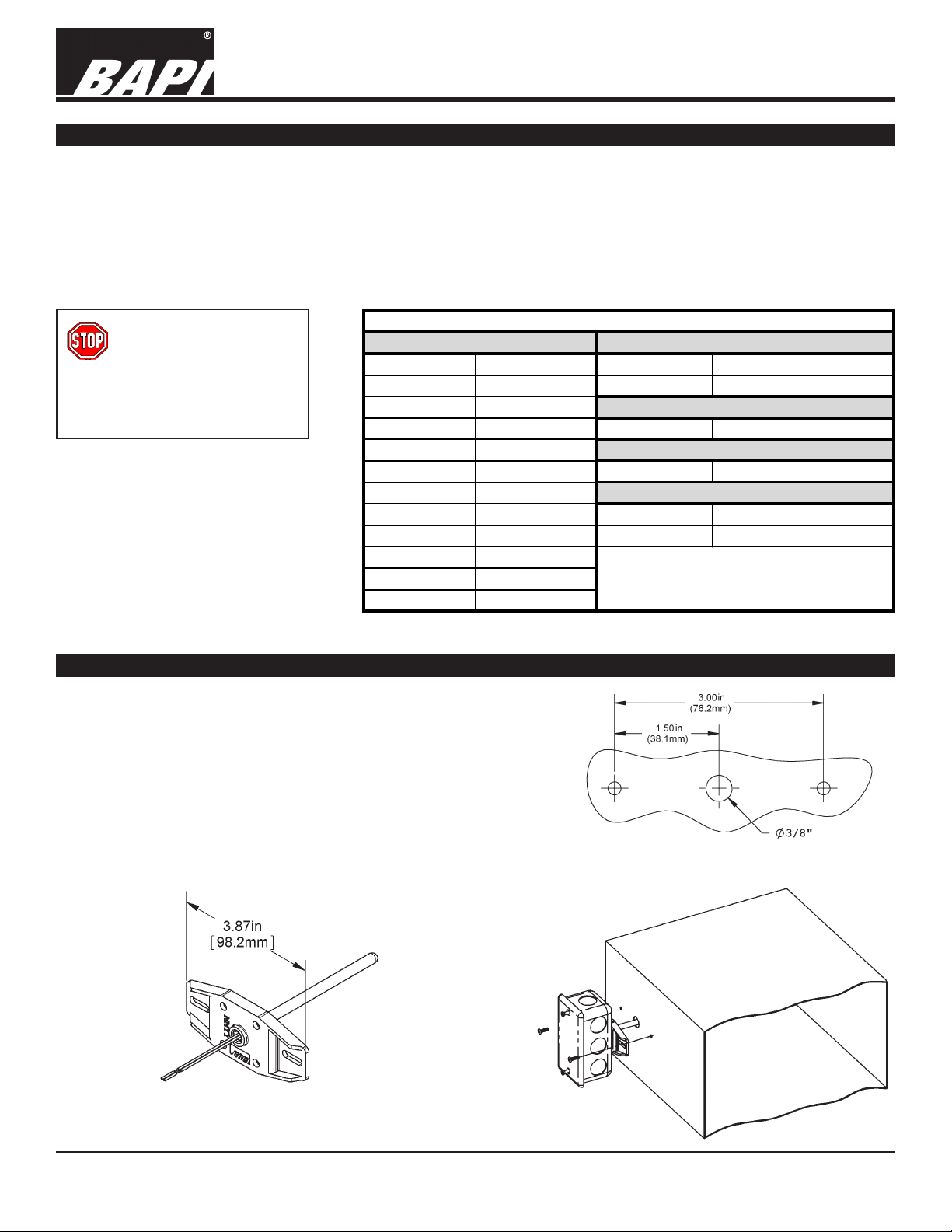
Junction Box (JB) and No Box (NB) Mounting Indoors
The junction box mount is intended for indoor mounting in
equipment rooms, plenums or occupied spaces. The gures
below show a typical junction box mounting in an air duct.
BAPI recommends using #8 sheet metal screws that need 1/8inch pilot holes to attach the sensor to the duct.
After placing the sensing element in the duct, secure the
mounting ange to the duct; center the plastic tting holding
the probe in the mounting hole. Make sure that the foam seals
the hole; do not over tighten the screws. No box units use the
same mounting holes as Junction Box units.
Nickel RTD
Silicon RTD
Platinum RTDs - 3 Wire
*In the 3-Wire RTD sensors listed above,
the two wires of similar color are
connected together.
Fig. 1: Junction Box (JB) or No Box (NB)
mounting holes
Fig. 3: No Box (NB)
Probe
Specications subject to change without notice.
Fig. 2: Junction
Box (JB) duct
installation
1 of 5
Page 2
Non-Room Thermistors and RTDs
Installation & Operations
9502_ins_therm_rtd_nrm
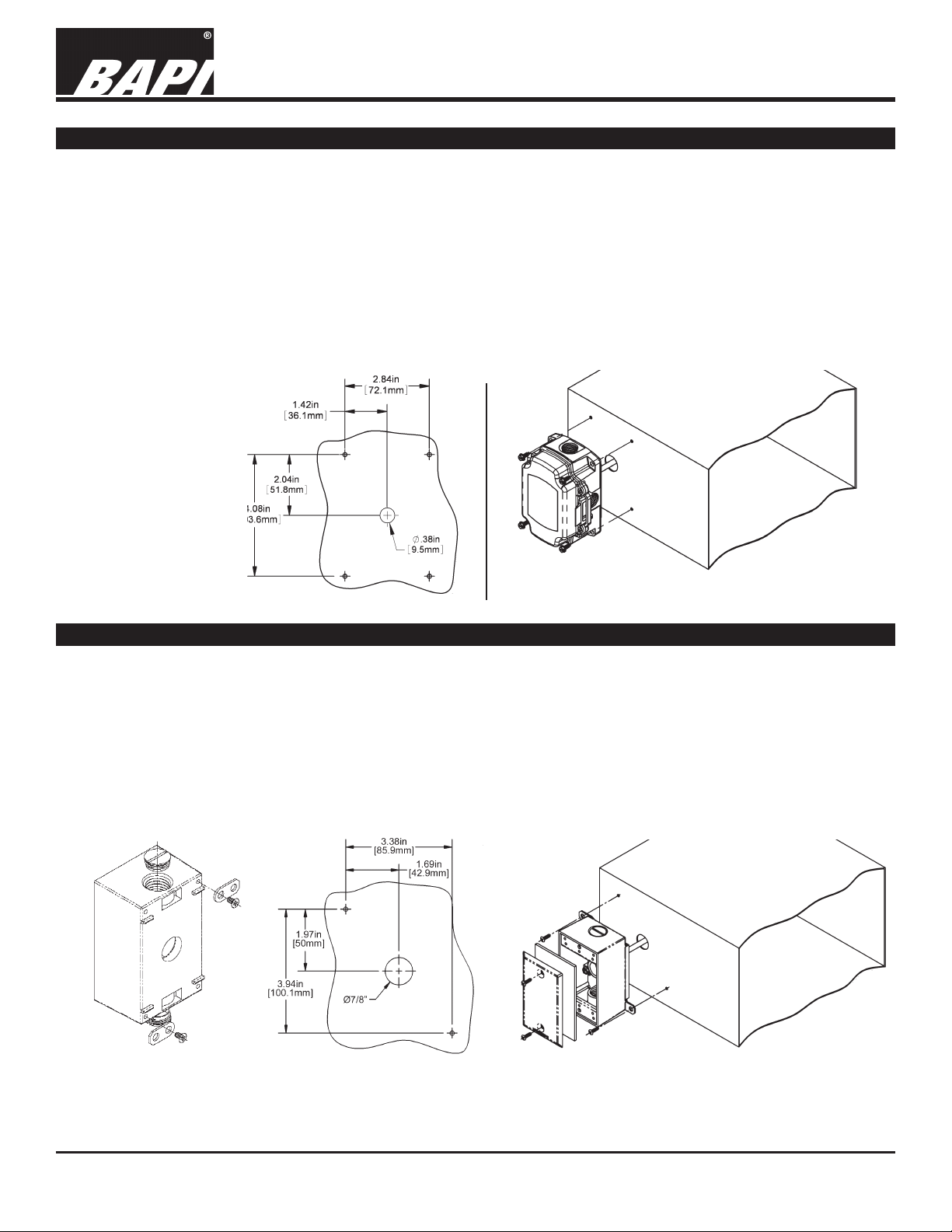
BAPI-Box (BB) Mounting Indoors
The BAPI-Box Enclosure is watertight and carries an IP66 rating which is similar to a NEMA 4X rating when the
included 6-32 screws are fastened on either side of the latch. The BAPI-Box Enclosure is made of high impact, UV
resistant polycarbonate and features a gasketed cover for a waterproof seal, a hinged cover to simplify installation,
horizontal or vertical mounting with multiple knockouts and a window in the cover for an LCD display.
Enclosure is available for the full line of BAPI duct, immersion, outside air and pressure sensors.
Mount the unit to its mounting surface with four #10 scres through the holes in the mounting feet. #10 sheet metal
screws require 5/32” (4mm) pilot holes. For concrete or cinder block, drill four 5/32” (4mm) holes, 1-3/4 inch (45mm)
deep. Make sure that all screws are started in their holes before tightening evenly. If unit has a foam gasket, only
squeeze to about 1/2 of its original thickness.
Be sure to seal conduit connector threads and holes in mounting surface to maintain the integrity of the box.
Fig 4: BAPI-Box (BB)
enclosure mounting
holes, rotate 90° for
horizontal mounting
The BAPI-Box
rev. 10/12/15
-
Fig. 5: BAPI-Box (BB) duct installation
Weatherproof (WP) Enclosure Mounting Indoors
The weatherproof box is intended for outdoor or equipment room mounting. Use the mounting tabs provided to
mount the weatherproof box as shown in the gure below. DO NOT drill screw holes through the back wall of the
box, this destroys the integrity of the box and may void the warranty.
The gures below show a typical weatherproof box mounting in an air duct. BAPI recommends using #8 sheet
metal screws that need 1/8-inch pilot holes to attach the sensor to the duct. After placing the sensing element in
the duct, secure the mounting tabs to the duct; center the plastic tting holding the probe in the mounting hole. Be
sure that the foam seals the hole; do not over tighten the screws. Place the foam gasket between the cover and the
box before securing the cover in place with the screws provided. T
threads of the box plugs or conduit connectors with caulk before screwing them into the waterproof box.
o keep water out of the box, be sure to coat the
Fig. 6:
Weatherproof (WP)
enclosure mounting tabs
Fig. 7:
Weatherproof (WP)
enclosure mounting holes
Specications subject to change without notice.
Fig. 8:
Weatherproof (WP) enclosure
duct installation
2 of 5
Page 3

Non-Room Thermistors and RTDs
Installation & Operations
9502_ins_therm_rtd_nrm
Weather Tight (EU) Enclosure Mounting Indoors
The Weather Tight (EU) enclosure is made from ABS plastic for indoor applications and a UV light stabilized
plastic for outdoor applications or indoor applications exposed to direct sun light. The gures below show a typical
Weathertight enclosure mounting in an air duct.
BAPI recommends using #8 sheet metal screws that need 1/8-inch pilot holes. After placing the sensing element in
the duct, secure the mounting feet to the duct; center the plastic tting holding the probe in the mounting hole. Do
not over tighten the screws but be sure that the foam insulation makes an airtight seal. T
when you are nished making terminations.
Fig. 10: Weather
Tight (EU) duct
installation
Fig. 9: Weather
Tight (EU)
enclosure
mounting holes
ighten the lid to two clicks
rev. 10/12/15
Weather Tight (EU) and Weatherproof (WP) Enclosure Mounting Outdoors
Do not mount in direct sunlight, preferably mount on the north side of the
building. Install with the sensor probe pointed down. For best correlation with
the local weather bureau’s temperature, position the end of the probe between
four feet and six and one-half feet above the ground. Drill a hole through your
mounting surface as shown in the gures below. Mount the unit to the surface
with a wiring knock out centered over the wiring hole. Pull the wiring into the
unit and terminate using sealant lled connectors. Best practice is to caulk the
wiring hole after the wiring is installed. Be sure that the foam on the back of
the unit makes a good weather tight seal. Use the mounting tabs provided to
mount the weatherproof box as shown in the gure below.
DO NOT drill screw holes through the back wall of the box, this destroys the
integrity of the box and may void the warranty. Note: Air temperature units
are shown. To keep water out of the box, be sure to coat the threads of the
box plugs or conduit connectors with caulk before screwing them into the
weatherproof box.
Weatherproof (WP) enclosure
mounting holes and outside
Fig. 11:
air installation
Fig. 12: Weather Tight (EU)
enclosure mounting holes and
outside air installation
Specications subject to change without notice.
3 of 5
Page 4

9502_ins_therm_rtd_nrm
Immersion Sensor Mounting
Place the thermowell into the pipe nipple
using Teon tape and/or pipe dope. Tighten
securely but do not over torque. Insert the
immersion sensor into the well with the plastic
tting screwing into the opening on the well.
Tighten the immersion sensor snugly by hand
without too much torque. Make sure that the
tip of the immersion sensor is in contact with
the bottom of the well.
The unit is designed so that the temperature
probe moves slightly into the junction box as
the sensor hits the bottom of the well. Figure
13 shows a junction box, but Weatherproof,
Weather Tight or BAPI-Box enclosures may
be used as well.
Non-Room Thermistors and RTDs
Installation & Operations
rev. 10/12/15
Fig. 13:
Cross section of
immersion unit
installation
Spring-Loaded Strap Mounting
The spring-loaded strap sensor is used when a large
section of insulation cannot be removed from a pipe.
The unit accommodates insulation of up to two inches
thick. Cut a 1.25” diameter hole in the insulation
and remove the insulation from the hole down to the
bare pipe. Be sure to remove all insulation and debris
from the hole. Place the copper pad on the end of
the spring-mounted foam into the hole; make sure it
makes good physical contact with the pipe. Tighten
the straps until the strap-mounting bracket contacts
the insulation. The spring-loaded strap on sensor is
sized for pipe diameters of 5 to 12.5”, including the
insulation.
Clamp On Strap Mounting
Place the clamp-on sensor on bare pipe, or a section
of pipe with the insulation removed. Make sure that
the copper pad on the foam is in good physical contact
with the pipe. Snug the straps so that the assembly
does not rotate around the pipe when moderate
pressure is applied to the junction box. Do not over
tighten. You may place pipe insulation over the whole
assembly. The clamp-on strap sensor is sized for bare
pipes of 2 to 4.5” in diameter. Add another pipe clamp
if needed.
Fig. 14:
Spring-Loaded Strap installation
Specications subject to change without notice.
Fig. 15:
Clamp-On Strap installation
4 of 5
Page 5

Non-Room Thermistors and RTDs
9502_ins_therm_rtd_nrm
Remote Sensor (RPFEP and FEP) Mounting Indoors
Mount the Weatherproof or the Weather Tight enclosures as shown
in the gures below. Mount with the wire connector down. Route
the temperature probe to the spot where you wish to measure the
temperature. Best practice is to tie down the wire every two feet. Make
sure to caulk the upper screw in plug on the Weatherproof enclosure.
Center mounting hole shown is only used if you are wiring through the
mounting surface.
Fig. 16:
Weatherproof (WP) enclosure
mounting holes and remote
probe installation
Installation & Operations
rev. 10/12/15
Fig. 17:
Weather
Tight (EU)
enclosure
mounting
holes and
remote
probe
installation
Diagnostics
Problems:
Controller reports temperature that is different
from the actual temperature of the location
Specications subject to change without notice.
Possible Solutions:
- Conrm the input is set up correctly in the front end software
- Verify that the wires are not physically shorted or open
- Check wiring for proper termination
- Disconnect wires and measure the sensor resistance with an
Ohmmeter to verify that the sensor output is correct. (See note
below)
Note: Measure the temperature at the sensor’s location using
an accurate temperature standard. Disconnect the temperature
sensor wires and measure the temperature sensor’s resistance
with an ohmmeter. Compare the temperature sensor’s
resistance to the appropriate temperature sensor table on
the BAPI website. If the measured resistance varies from
the temperature table by more than 5%, call BAPI technical
support. BAPI’s website is found at www.bapihvac.com; click on
“Resource Library” and “Sensor Specs”, then click on the type of
sensor you have.
5 of 5
 Loading...