

Page 1
20918_ins_Immersion_Active
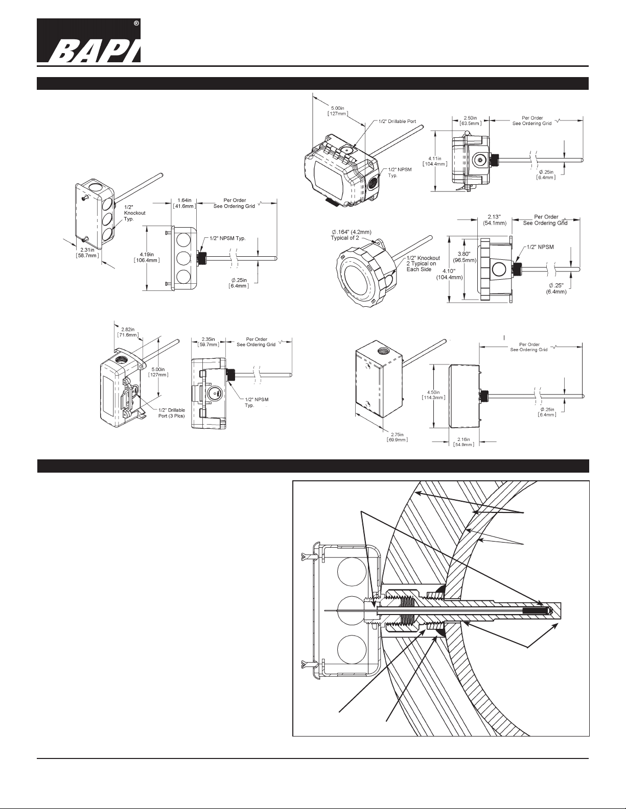
Overview and Identication
The BA/#-I Immersion temperature transmitter is
made for thermowell mounting and measurement
in water pipes, water tanks or cooling tower sump
applications. The Stainless Steel probe is made in
different lengths for a custom thermowell t.
Fig 2:
Junction Box
(JB)
Immersion Temperature Transmitters
BA/#-I
Fig 1: BAPI-Box (BB)
Fig 3: Weather Tight (EU)
Temperature Transmitter
Installation & Operations
rev. 06/30/15
Fig 4:
BAPI-Box 2
(BB2)
Thermowell Installation
BAPI’s immersion probes are designed to be
installed in a thermowell. to install a thermowell,
a pipe tter typically drills a ¾-inch hole into the
pipe where the thermowell is needed. A customerprovided tting, called a Threadolet or Weldolet, is
welded to the pipe over the hole. The Threadolet
has a ½” NPT thread in the center. Thread sealant
such as Teon tape or pipe dope is applied to the ½”
NPT threads of the thermowell. The thermowell is
then inserted into the Threadolet and tightened.
Figure 6 shows a 4” thermowell and 4” immersion
probe installed into 12” pipe. Usually thermowells
are sized to extend to the center of the pipe;
however, shorter thermowells will give proper
temperature readings if properly installed.
Since the wall thickness of the pipe commonly used
for HVAC plumbing is ½-inch, the thermowell sticks
four inches into the pipe. The four-inch distance
called out by a four-inch thermowell is the distance
from the inside surface of the pipe to the end of the
thermowell.
Fig 5:
Weatherproof
(WP)
6.5” Overall
Probe Length
Threadolet
2” Thick
Pipe Insulation
1/2” Thick
Pipe Wall
(Schedule 80)
4” Thermowell
Insertion Length
Fig 6: Typical
Immersion Probe
Installed in a
Thermowell.
Weld
Specications subject to change without notice.
1 of 4
Page 2
Immersion Temperature Transmitters
BA/#-I
20918_ins_Immersion_Active
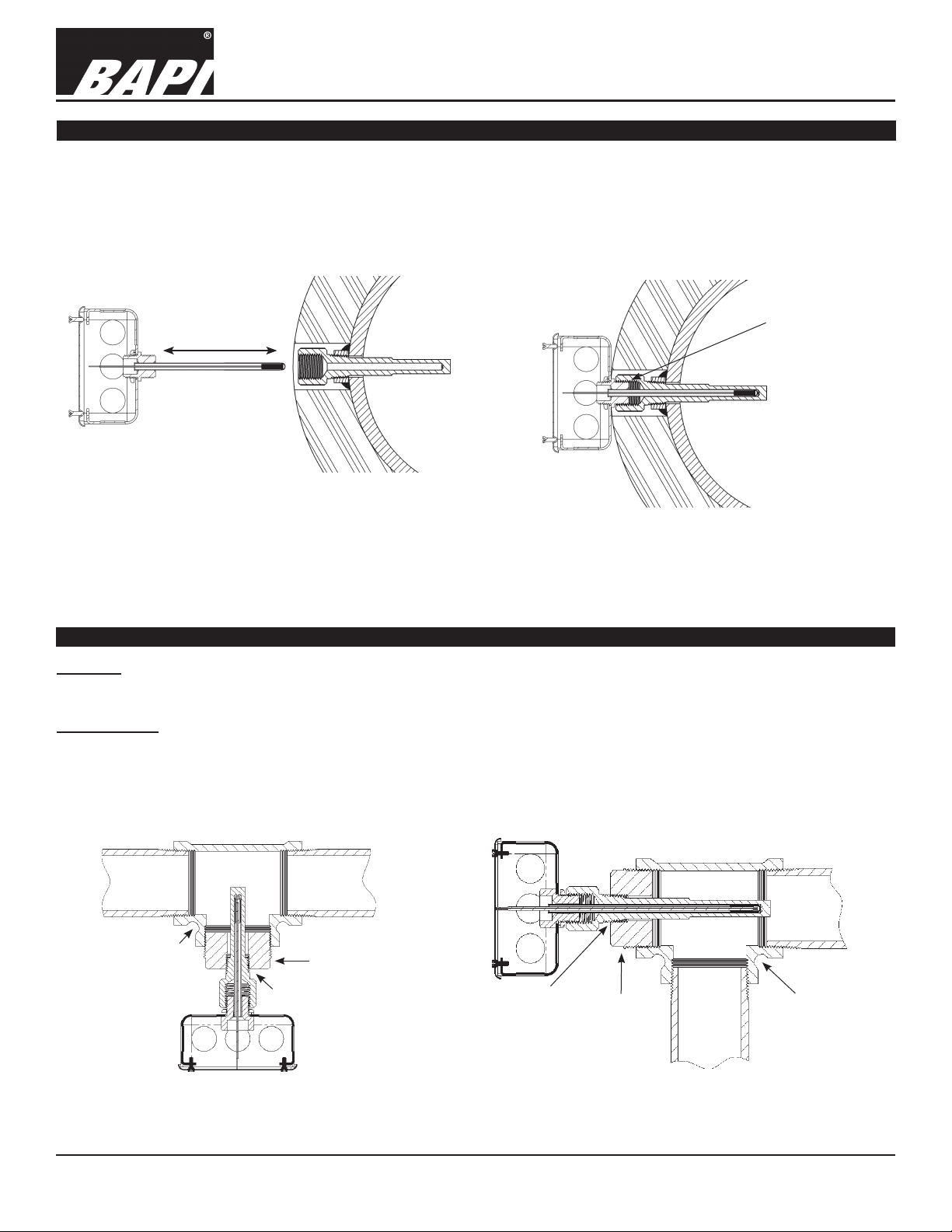
Immersion Sensor Installation
Immersion probes come with a plastic tting that screws into the threads at the top of the thermowell. Pull the probe away
from the plastic tting until the probe is fullly extended. Insert the immersion probe into the thermowell until the plastic
ttings come into contact with the threads in the thermowell. Hand tighten the immersion sensor snugly into the
thermowell without too much torque. The unit is designed so that the temperature probe slides back into the enclosure as
the sensor contacts the bottom of the thermowell. Make sure that the tip of the immersion sensor probe is in good contact
with the bottom of the thermowell by pushing on the aired end of the probe until the tip bottoms out in the thermowell.
Length Per Order
*Sensor Slides
1. Pull Probe to
Extend Fully
2. Insert
3. Hand Tighten
Fig 7: Immersion Sensor Before Insertion
*As the immersion sensor is hand threaded into the
thermowell, the air end of the probe will be pushed back
into the enclosure as the probe tip bottoms out in the
thermowell. The probe can slide up to 1.6”. The Junction
Box enclosure is shown above but the process is the
same for the other enclosure styles.
Fig 8: Immersion sensor after insertion into
the thermowell.
(Junction box enclosure shown above.)
Temperature Transmitter
Installation & Operations
rev. 06/30/15
Hand tighten
immersion probe
threads into the
thermowell
Installation in Pipes Less than 3” in Diameter
T- Mount
Figure 9 shows how a 2” Tee and a 1/2” to 2” bushing allows a 2” thermowell to measure the temperature of the contents
of a 2” water pipe. Be sure to use a thread sealant on the outside threads of the thermowell.
Corner Mount
Figure 5 shows how a pipe Tee can be used in an elbow application. A 2” tee and a 1/2” to 2” bushing allows a 4”
thermowell to measure the temperature of the contents of a 2” water pipe.
Note: Temperatures in pipes as small as 1-1/4” may be measured by this method. In small pipes, the diameter of the
thermowell may become a signicant obstruction, so be sure to check for proper ow rates after installation is complete.
T-Pipe Fitting
Reducer
1/2 Inch NPT
1/2 Inch NPT
Reducer
T-Pipe Fitting
Fig 9: Typical T-Mount
Fig 10: Typical Corner Mount
Specications subject to change without notice.
2 of 4
Page 3

Immersion Temperature Transmitters
BA/#-I
20918_ins_Immersion_Active
Wiring & Termination
BAPI recommends using twisted pair of at least 22AWG and sealant lled connectors for all wire connections. Larger
gauge wire may be required for long runs. All wiring must comply with the National Electric Code (NEC) and local codes.
Do NOT run this device’s wiring in the same conduit as high or low voltage AC power wiring. BAPI’s tests show that inaccurate signal levels are possible when AC power wiring is present in the same conduit as the sensor wires.
Temperature Transmitter
Installation & Operations
rev. 06/30/15
Fig. 12: Typical
RTD 4 to 20mA
Transmitter with
Terminals
Fig. 13: Typical Thermistor
4 to 20mA Transmitter
Fig. 11: Typical
RTD 4 to 20 mA
Transmitter with
Flying Leads
Fig. 14: Typical Thermistor
Voltage Transmitter
Diagnostics
Possible Problems: Possible Solutions:
•
Unit will not operate. - Measure the power supply voltage by placing a voltmeter across the transmitter’s (+) and
- Check if the RTD wires are physically open or shorted together and are terminated to the
- Measure the physical temperature at the temperature sensor’s location using an accurate
(-) terminal. Make sure that it matches the drawings above and power requirements in the
specications.
transmitter.
temperature standard. Disconnect the temperature sensor wires and measure the
temperature sensor’s resistance with an ohmmeter. Compare the temperature sensor’s
resistance to the appropriate temperature sensor table on the BAPI web site.
• The reading is incorrect in the controller.
- For a 4-20mA current transmitter measure the transmitter current by placing an ammeter
Voltage Temperature Equation
T = TLow + (V x TSpan)
VSpan
T = Temperature at sensor
TLow = Low temperature of span
THigh = High temperature of span
TSpan = THigh - TLow
VLow = Low transmitter voltage
usually=(0, 1 or 2v)
VHigh = High transmitter voltage
usually=(5 or 10v)
VSpan = VHigh - VLow
V = Signal reading in volts
- Determine if the input is set up correctly in the controllers and BAS software.
in series with the controller input. The current should read according to the “4-20mA
Temperature Equation” shown below.
- For a voltage transmitter, measure the signal with a volt meter (Orange or Orange/Black to
Black). The signal should read according to the “Voltage Temperature Equation” shown below.
4-20mA Temperature Equation
T = TLow + (A -4) x (TSpan)
16
T = Temperature at sensor
TLow = Low temperature of span
THigh = High temperature of span
TSpan = THigh - TLow
A = Signal reading in mA
Specications subject to change without notice.
3 of 4
Page 4

20918_ins_Immersion_Active
Specications
Immersion Temperature Transmitters
BA/#-I
Temperature Transmitter
Installation & Operations
rev. 06/30/15
RTD Transmitter
Power Required: 7 to 40VDC
Transmitter Output: 4 to 20mA, 850Ω@24VDC
Output Wiring: 2 wire loop
Output Limits: <1mA (short), <22.35mA (open)
Span:
Zero:
Min. 30ºF (17ºC), Max 1000ºF, (555ºC)
Min. -148°F (-100°C), Max 900ºF (482ºC)
Zero & Span Adjust: 10% of span
Accuracy: ±0.065% of span
Linearity: ±0.125% of span
Power Output Shift: ±0.009% of span
RTD Sensor: 2 wire Platinum (Pt), 385 curve
Transmitter Ambient -4 to 158ºF(-20 to 70ºC)
0 to 95% RH, Non-condensing
Thermistor Transmitter
Supply Voltage:
10 to 35 VDC (0 to 5 VDC or 4 to 20 mA Outputs)
15 to 35 VDC (0 to 10 VDC Output)
12 to 24 VAC (0 to 5 VDC Outputs)
15 to 24 VAC (0 to 10 VDC Output)
Transmitter Output: 4 to 20mA, 700Ω@24VDC
0 to 5 & 0 to 10VDC, 10KΩ min
Output Wiring: 2 & 3 wire (See wiring detail on pg. 3)
Transmitter Limits: -40 to 185ºF, (-40 to 85ºC)
Accuracy: ±1.015ºC, from (0 to 65ºC)
Linearity: ±0.065ºC, from (0 to 65ºC)
Resolution: Span/1024
Thermistor Sensor: 10K-2 Thermistor, 10KΩ @77ºF
Transmitter Ambient: 32 to 158ºF, (0º to 70ºC)
0 to 95% RH, Noncondensing
Thermistor:
10K-2, Thermal Resistor (Bare Sensor)
Accuracy (Std): ±0.36ºF, (±0.2ºC)
Accuracy (High): ±0.18ºF, (±0.1ºC), [XP] option
Stability: < 0.036ºF/Year, (<0.02ºC/Year)
Heat Dissipation: 2.7 mW/ºC
Probe Range: -40º to 221ºF (-40º to 105ºC)
Wire Colors:
Standard: Yellow/Yellow (no polarity)
High Acc. [XP]: Yellow/Yellow (no polarity)
RTD:
Resistance Temp Device (Bare Sensor)
Platinum (Pt): 100Ω and 1KΩ @0ºC, 385 curve,
Pt Accuracy (Std): 0.12% @Ref, or ±0.55ºF, (±0.3ºC)
Pt Accuracy (High): 0.06% @Ref, or ±0.277ºF,
(±0.15ºC), [A]option
Pt Stability: ±0.25ºF, (±0.14ºC)
Pt Self Heating: 0.4 ºC/mW @0ºC
Pt Probe Range: -40º to 221ºF, (-40 to 105ºC)
Wire Colors:
General color code (other colors possible)
1KΩ, Class B Orange/Orange (no polarity)
1KΩ, Class A Orange/White (no polarity)
100Ω, Class B Red/Red (no polarity)
100Ω, Class A Red/Red-w/black stripe (no polarity)
Sensitivity: Approximate @ 32ºF (0ºC)
Thermistor: Non-linier - (See www.bapihvac.com,
click “Sensor Specs”)
RTD (Pt): 3.85Ω/ºC for 1KΩ RTD
0.385Ω/ºC for 100Ω RTD
Lead Wire: 22awg stranded
Insulation: Etched Teon, Plenum rated
Probe: Flexible Copper tube, 0.19”OD
Probe Length:
Duct Gasket:
2’, 4’, 8’ or per order
1/4” Closed cell foam (impervious to mold)
Mounting: Extension tabs (ears), 3/16” holes
Enclosure Types: (Part number designator in bold)
J-Box: -JB, w/ eight ½” knock-outs
Weatherproof: -WP, w/ two ½” FNPT entries, (Bell box)
BAPI-Box: -BB, w/ four ½” NPSM & one ½” drill-out
BAPI-Box 2:
-BB2, w/ three ½” NPSM & three ½” drill-outs
Weather Tight: -EU, EUO, w/ two ½” knock-outs
Enclosure Ratings: (Part number designator in bold)
J-Box: -JB, NEMA 1
Weatherproof: -WP, NEMA 3R, IP14
BAPI-Box: -BB, NEMA 4, IP66, UV Rated
BAPI-Box 2: -BB2, NEMA 4, IP66, UV Rated
Weather Tight: -EU, NEMA 4, IP66
Weather Tight: -EUO, NEMA 4, IP66, UV rated
Enclosure Material: (Part number designator in bold)
J-Box: -JB, UL94H-B
Weatherproof: -WP, Cast Aluminum, UV rated
BAPI-Box: -BB, Polycarbonate, UL94V-0, UV rated
BAPI-Box 2: -BB2, Polycarbonate, UL94V-0, UV rated
Weather Tight: -EU, ABS Plastic, UL94V-0
Weather Tight:
-EUO, ASA (Geloy) Plastic, UL94V-0, UV rated
Ambient (Encl.) 0 to 100% RH, Non-condensing
J-Box -JB, -40ºF to 212ºF, (-40º to 100ºC)
Weatherproof -WP, -40ºF to 212ºF, (-40º to 100ºC)
BAPI-Box -BB, -40ºF to 185ºF, (-40º to 85ºC)
BAPI-Box 2 -BB2, -40ºF to 185ºF, (-40º to 85ºC)
Weather Tight -EUO, EU, -40ºF to 185ºF, (-40º to 85ºC)
Agency RoHS
PT=DIN43760, IEC Pub 751-1983,
JIS C1604-1989
Specications subject to change without notice.
4 of 4
 Loading...