

Page 1
Wireless Room Temperature and Humidity Transmitter
(Units without Temperature Setpoint or Override)
Installation and Operating Instructions
17616_ins_wireless_temp_hum_xmtr
Wireless Temperature and Humidity Transmitter Overview and Indentication
The BAPI Wireless Temperature and Humidity Transmitter measures the
room temperature and Relative Humidity and transmits the data at 418MHz
or 433MHz RF to a receiver. The transmitter is mounted in a BAPI-Stat 2 style
enclosure and has maximum in-building range of open-air range of 100 feet.
The transmit rate is approximately once every 20 seconds with an estimated
battery life of 5 to 8 years using two high-capacity 3.6V lithium batteries. Each
transmitter has a unique address with built-in error detection. Each variable
sent by the transmitter is picked up by the receiver and converted by a separate BAPI Analog Output Module to a voltage, current or resistance signal
which is sent to the controller.
Fig. 1:
Wireless Room
Temperature
Transmitter
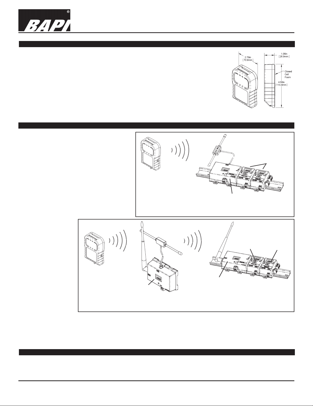
Complete Wireless System Overview
418 MHz System:
The Transmitter measures the temperature or
temp/humidity and transmits the data at 418MHz to
the 418 MHz Receiver up to 100 feet away. The optional temperature setpoint and override status are
also transmitted at 418 MHz to the receiver. The
transmit rate is about once every 20 seconds with
an estimated battery life of 5 to 8 years.
The information sent by the Transmitter is picked
up by the 418 MHz Receiver and passed along
to the Analog Output Modules. Each transmitted
variable (temperature, humidity, setpoint, etc.) is
converted by a separate output module into an
analog resistance, voltage, current or relay contact
which is hard wired to the analog inputs of the BAS
Transmitter
Transmits the
Temperature,
Humidity,
Setpoint and
Override Info
418 MHz
Up to 100 Feet
Fig. 2:
418 MHz
Wireless
System
Receives the Temperature, Humidity, Setpoint
and Override Info from the Transmitter and
passes it on to the Analog Output Modules
Analog Output Modules
Converts the Temperature,
Humidity, Setpoint and
Override Info into an analog
resistance, voltage, current
or relay for the BAS controller
418 MHz Receiver
controller.
900 MHz System:
The Transmitter measures the room temperature or temp/humidity and
transmits the data at
418MHz to a Repeater
up to 100 feet away. The
optional temperature setpoint and override status
are also transmitted at
418 MHz to the Repeater.
The transmit rate is approximately once every
20 seconds with an
estimated battery life of 5
to 8 years.
Transmitter
Transmits the
Temperature,
Humidity,
Setpoint and
Override Info
418 MHz
Up to 100
Feet
Repeater
Receives the 418 MHz
Info from the Transmitter
and Re-Transmits it at 900
MHz up to 1,000 feet
900 MHz
Up to 1,000
Feet
900 MHz Receiver
Receives the Temperature, Humidity, Setpoint
and Override Info from the Repeater and
passes it on to the Analog Output Modules
Fig. 3: 900 MHz Wireless System
Analog Output Modules
Converts the Temperature,
Humidity, Setpoint and
Override Info into an analog
resistance, voltage, current
or relay for the BAS controller
The 418 MHz information sent by the Transmitter is picked up by the Repeater and then Re-Transmitted at 900 MHz to a 900 MHz Receiver up to
1,000 feet away. The 900 MHz receiver picks up the information from the repeater and then passes it along to the Analog Output
Modules. Each transmitted variable (temperature, humidity, etc.) is converted by a separate output module into an analog resistance, voltage, current or relay contact which is hard wired to the analog inputs of the BAS controller.
rev. 04/21/15
Customer Provided Tools and Materials
#2 Philips Screwdriver, 1/8” Screwdriver with 1/16” Allen wrench (BA/116W), Drill with 3/16” (4.7mm) bit
Specications subject to change without notice.
1 of 5
Page 2
Wireless Room Temperature and Humidity Transmitter
(Units without Temperature Setpoint or Override)
Installation and Operating Instructions
17616_ins_wireless_temp_hum_xmtr
Analog Output Module Training
The installation process requires that each transmitter is trained to its associated
output modules so that they communicate with each other. Pushing buttons in a
dened sequence on the units will bind them together.
The training process is easiest on a test bench with the units within arm’s reach
of each other. Training can be done in the eld but requires two people and a
set of walkie talkies or cell phones. Be sure to place an identication mark on
the transmitter and associated output modules after they have been trained so
that they can be matched together at the job site.
The temperature and humidity variables each require a separate output module.
Perform the training sequence for each output module. Any transmitted variable
can be trained to more than one output module. If a Repeater is used in the
system, be sure it is powered and within reception range of the transmitter and
the 900 MHz Receiver to train the output modules.
TEMPERATURE OR HUMIDITY VARIABLE TRAINING
1. To train an output module to a temperature or humidity variable, select the
Resistance, Voltage or Current Output Module calibrated to the proper
temperature or humidity range and connect it to the wireless receiver. Note:
Multiple output modules can be trained to the same variable if desired.
2. Apply power to the receiver which will supply power to the connected output
modules. The power LED on the receiver will light and remain lit. (Current Output Modules
must have loop power supplied to the module itself before they can be trained.)
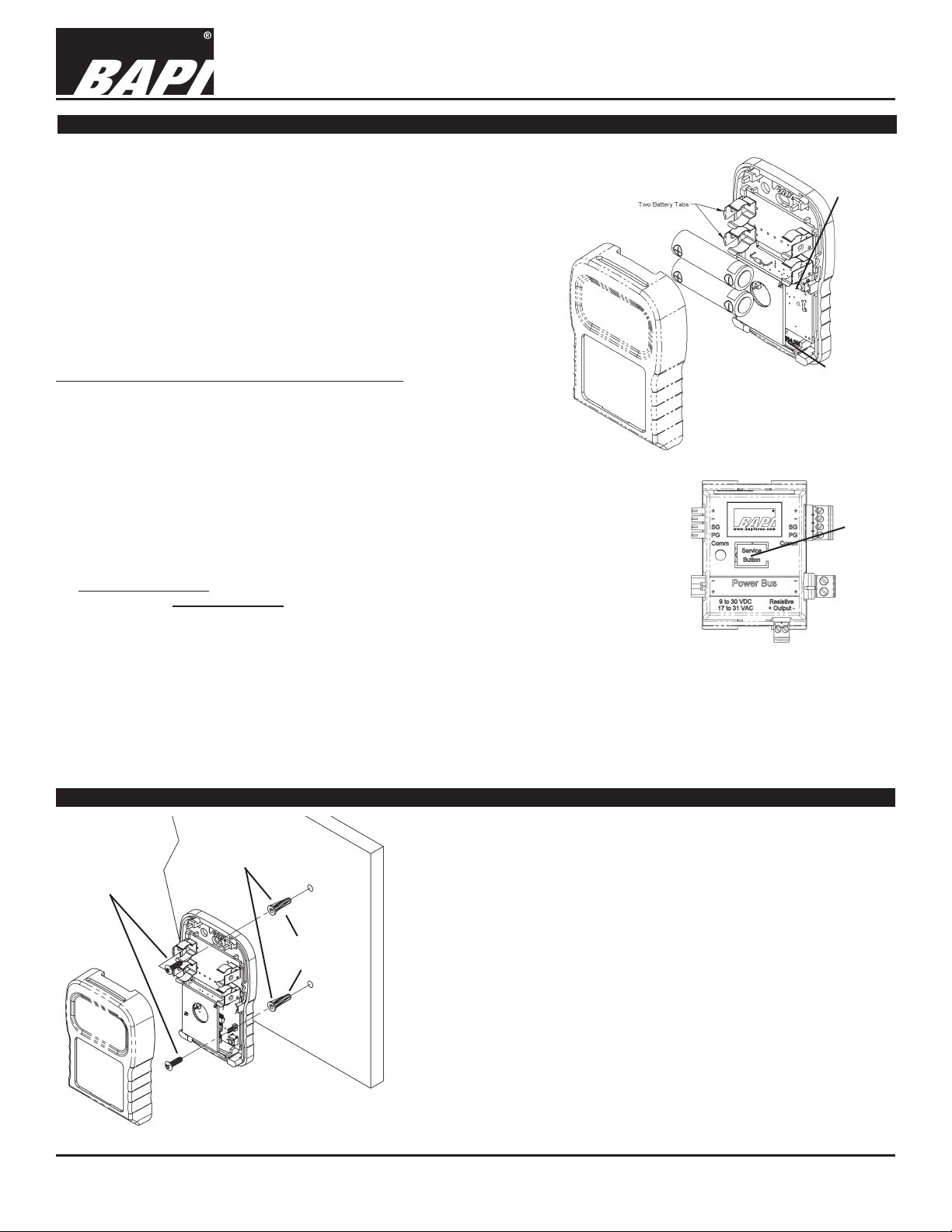
3. Remove the cover of the room transmitter and remove the battery tabs or install the batteries,
observing polarity as shown in Fig 3. Or open the cover of the BAPI-Box on non-room
transmitters and remove the battery tabs or install the batteries as shown in Fig 4. The “transmit
LED” will ash about once every 20 seconds, indicating a transmission. (The ash is very quick.)
4. Press and hold down the “Service Button” on the top of the output module (Fig 5) that you wish
to train. Then, press and release the “training button” (see Fig 3 & Fig 4) on the transmitter.
When the output module receives the “training transmission” from the transmitter, the output
module’s red LED will light steady. Release the “Service Button” on the output module and the
red LED will go out. The transmitter and output module are now trained to each other. During
normal operation, the output module’s LED will ash about once every 20 seconds indicating
data reception from the transmitter trained to it.
Note: Combination transmitters send both the temperature and humidity information when the “Training Button” is pressed.
However, each Analog Output Module is congured at the time of order as a temperature, humidity, setpoint or override
module and will only recognize the relevant data and will ignore the rest.
5.
Mount the transmitter at the desired location, removing the batteries if needed. (The units will remain trained to one another through
power failures and battery replacement.)
Battery polarity is
important or damage
to the unit may occur
Fig. 4:
Room Transmitter battery
installation and training
rev. 04/21/15
Training
Button
Transmit
LED
Output
Module
Service
Button
Fig. 5:
Output
Module
Mounting of the Room Transmitter
Provided
Drywall
Anchors
Provided #6 x 1” Screws
(80mm)
Fig. 6: Drywall Mounting
Note: The transmitter should have been trained to the output module at
this point of the installation.
Drywall Mounting
1. Place the base plate against the wall where you want to mount the sensor.
Typically 5 feet above the oor.
3.25”
Specications subject to change without notice.
2. Using a pencil, mark out the two mounting holes.
3. Drill two 3/16” (4.7 mm) holes in the center of each marked mounting hole.
Insert a drywall anchor into each hole.
4. Secure the base to the drywall anchors using the #6 x 1 inch mounting
screws provided.
5. Install provided batteries or pull battery tabs and follow polarity as shown
in gure 3 or damage may occur. The unit will work on just one battery
however the battery life will be cut in half.
6. Attach cover by latching it to the top of the base, rotating the cover down
and snapping it into place.
7. Secure the cover by backing out the lock-down screws using a 1/16” Allen
wrench until they are ush with the bottom of the cover.
2 of 5
Page 3

Wireless Room Temperature and Humidity Transmitter
(Units without Temperature Setpoint or Override)
Installation and Operating Instructions
17616_ins_wireless_temp_hum_xmtr
Mounting of the 418 MHz Receiver, 900 MHz Receiver and Analog Output Modules
rev. 04/21/15
The 418 MHz Receiver, 900 MHz Receiver and Analog Output Modules can be
mounted in snap track, DIN Rail or surface mounted. The text and gures refer to
the 418 MHz Receiver, but the mounting process is the same for both receivers.
SNAPTRACK MOUNTING
Push in the blue mounting tabs on the bottom of the receiver and output modules.
These units will now t into the board slots of 2.75” snap track. Insert the receiver
at the far left of the snap track, then insert each analog output module and slide it
to the left until its connectors are fully mated into the receiver or the next analog
output module. You may attach up to 127 analog output modules to a receiver.
If your output modules cannot t in one piece of snap track, then mount another
piece of snap track nearby and insert the additional modules. Connect wires from
the right side of the rst string of modules to the left side of the second string of
modules on the second snap track. (See “Extending the RS485
Network” on pg. 5.) This conguration requires one or more
Pluggable Terminal Block Connector Kits (BA/AOM-CONN).
DIN RAIL MOUNTING
Push out the blue mounting tabs on the bottom of the
receiver and output modules. These units will now snap
onto DIN Rail. Catch the EZ mount hook on the edge of the
DIN rail as shown in Fig 9. Then rotate into place.
Attach the receiver at the far left of the DIN Rail, then attach
each analog output module and slide it to the left until its
connectors are fully mated into the receiver or the next
analog output module. You may attach up to 127 analog
output modules to a receiver.
If your output modules cannot t onto one piece of DIN Rail,
then mount another piece nearby and attach your additional modules. Connect wires from the
right side of the rst string of modules to the left side of the second string of modules on the
second DIN Rail. (See “Extending the RS485 Network...” on pg. 5.) This conguration requires
one or more Pluggable Terminal Block Connector Kits (BA/AOM-CONN).
Receiver & output modules mounted on DIN Rail.
Fig. 8:
Fig. 7:
Receiver
and output
modules
mounted in
snaptrack.
Fig. 9:
Catch the EZ Mount
hook on the edge of
the DIN Rail, then
rotate into place.
SURFACE MOUNTING
Push out the blue mounting tabs on the bottom of the receiver and output modules. Attach the
receiver to the surface by inserting a screw in each blue tab. Attach Analog Output Modules by
placing each one against the surface and sliding it to the left until its connectors are fully mated
into the receiver or the next analog output module. Attach each module to the surface with two
screws, one in each blue tab. You may attach up to 127 analog output modules to a receiver.
If your output modules cannot t in one straight line on the surface, then mount a second string
of modules nearby. Connect wires from the right side of the rst string of modules to the left
side of the second string of modules. (See “Extending the RS485 Network...” on pg. 5.) This
conguration requires one or more Pluggable Terminal Block Connector Kits (BA/AOM-CONN).
Wireless Temperature and Humidity Transmitter Specications
Supply Power: Two AA 3.6V Lith. batteries, 2.25 AH
5 to 8 year battery life at 20 second transmit rate
Inputs: Temperature - Thermistor
Relative Humidity - Capacitive
Accuracy: ±0.54°F (±0.3°C) / ±2% RH
Transmitted Range: -40 to 185°F (-40 to 85°C ) • 0-100% RH
Antenna: Built inside the enclosure
Environmental Operation Range:
Temp: 32° to 140°F (0° to 60°C)
Humidity: 5% to 95% RH non-condensing
Enclosure Material & Rating: ABS Plastic, UL94 V-0
Radio Frequency: 418 MHz North America
Transmitter Interval: ~20 seconds
FCC Approval #:
T4F061213RSO (418MHz Room Transmitter Only)
T4F060811TEMP (418MHz Temperature Probe Only)
T4F060811RH (418MHz Temp & Humidity Probe Only)
OUR9XSTREAM (Repeater Unit Only)
Compliance: This device complies with Part 15 of the FCC rules
Operation is subject to the following conditions.
1. This device may not cause harmful interference.
2. This device must accept any interference received, including
interference that may cause undesired operation.
FCC Radio Frequency Interference Statement:
This equipment has been tested and found to comply with the limits
for a Class B digital device, pursuant to Part 15, Subpart B, of the
FCC Rules. This equipment generates, uses, and can radiate radio
frequency energy. If not installed and used in accordance with the
instructions, it may cause interference to radio communications.
Fig. 10: Receiver and output
modules surface mounted.
Specications subject to change without notice.
3 of 5
Page 4

Wireless Room Temperature and Humidity Transmitter
(Units without Temperature Setpoint or Override)
Installation and Operating Instructions
17616_ins_wireless_temp_hum_xmtr
418 MHz Receiver and 900 MHz Receiver with Analog Output Modules Termination
rev. 04/21/15
418 MHz System
418 MHz Receiver
System Power Supply
9 to 30VDC or 17 to 31VAC
Power for the Power Bus can be
supplied to the receiver or to the
Analog Output Module on the far right
of the string of modules, but not to both
places.
The Power Bus must be connected to
the controller “-” power terminal.
Resistance
Output Module
The Resistive Thermistor Temp.
Signal is Polarity Sensitive to the
Controller and Must Have Less
than a 5VDC Bias Voltage.
Both “+” and “-” must be
connected to the controller
signal input and the negative “-”
connected to the power supply
negative “-”
Voltage
Output Module
Current Output Module
Requires loop power
before it can be trained.
0 to 5VDC or
0 to 10VDC
Analog Signal
Current Loop
Power
Supply
9 to 36VDC
4 to 20mA Current
Loop Signal to the
Controller
Relay
Output Module
Solid State Relay
40 VAC/VDC Max
150 mA Max
1 uA Leakage Max
RS-485 Bus
To Other Analog
Output Modules
Fig 11: 418 MHz Receiver and Output Module System Wiring
Termination Notes for 418 MHz and 900 MHz Systems:
1. The wireless receiver and Analog Output Modules are interconnected and require module power along the “Power Bus”
terminals. The bus can be powered from either the receiver end on the left or the last output module on the right side. Be sure
you have enough DC current or AC VA for all the devices on the bus.
2. The Current Output Module (BA/COM) signal is LOOP POWERED and must be externally powered with 9 to 36 VDC
separate from the Power Bus. The Loop Power must be connected to the Current Output Module before it can be trained.
3. Be sure to follow the polarity (+ or –) symbols listed on each receiver and the output modules to maintain communication and
Power Bus integrity.
900 MHz System
900 MHz Receiver
System Power Supply
9 to 15VDC
Power for the Power Bus can be
supplied to the receiver or to the
Analog Output Module on the far right
of the string of modules, but not to
both places.
The Power Bus must be connected to
the controller “-” power terminal.
Resistance
Output Module
The Resistive Thermistor Temp.
Signal is Polarity Sensitive to the
Controller and Must Have Less
than a 5VDC Bias Voltage.
Both “+” and “-” must be
connected to the controller
signal input and the negative “-”
connected to the power supply
negative “-”
Specications subject to change without notice.
Voltage
Output Module
0 to 5VDC or
0 to 10VDC
Analog Signal
Fig. 12: 900 MHz Receiver and Output Module System Wiring
Current Output Module
Requires loop power
before it can be trained.
Current Loop
Power
Supply
9 to 36VDC
4 to 20mA Current
Loop Signal to the
Controller
Relay
Output Module
Solid State Relay
40 VAC/VDC Max
150 mA Max
1 uA Leakage Max
RS-485 Bus
To Other Analog
Output Modules
4 of 5
Page 5

Wireless Room Temperature and Humidity Transmitter
(Units without Temperature Setpoint or Override)
Installation and Operating Instructions
17616_ins_wireless_temp_hum_xmtr
Extending the RS485 Network between the Receiver and the Analog Output Modules
The Analog Output Modules may be mounted up to 4,000 feet away from the receiver. The total length of all the shielded, twisted
pair (TSP) cables shown in Fig 13 is 4,000 feet (1,220 meters). Connect the terminals together as shown in Fig 13. If the distance from the receiver to the group of Analog Output Modules is greater than 100 feet (30 meters), provide a separate power
supply for that group of
Output Modules. BAPI’s
RS485 TSP Wiring RS485 TSP Wiring
VC350A-EZ Voltage
Conv. and a small
transformer are a perfect
solution.
rev. 04/21/15
Note: This conguration
requires one or more
Receiver
Pluggable Terminal
Block Kits for the extra
wire terminations on the
left and right side of the
Output Modules. Each kit
includes 4 connectors.
Pluggable Terminal Block
Kit (BA/AOM-CONN)
Fig. 13: Extended RS485 Network between the Receiver and the Analog Output Modules
Wireless System Diagnostics
Possible Problems:
Temperature or Humidity is reading
its low limit or high limit, or the LED
at the top of the Analog Output Module is blinking rapidly:
Analog Output Modules Analog Output Modules
BAPI
VC350A
EZ Voltage
Converter
Transformer
BAPI
VC350A
EZ Voltage
Converter
Transformer
BAPI
VC350A
EZ Voltage
Converter
Transformer
Possible Solutions:
- Check for proper wiring and connections from the output modules to the controller.
- Check to see if the controller’s software is congured properly.
- Check for proper power to the receiver, repeater (if used) and output modules.
- Retrain the Analog Output Module.
- Check that the associated transmitter is transmitting (the LED will ash about once
every 20 seconds when it transmits). If not, replace the batteries. Check that the
associated receiver is receiving the tranmissions (its LED will blink right after the
transmitter LED if it receives that transmission.) If it is not receiving the transmissions,
move it closer to the transmitter or reposition the antenna for maximum reception.
Note: The receiver will receive transmissions from all transmitters that are within
range, not just the one you are testing.
Temperature or Humidity reading is
- Retrain the Analog Output Module.
coming out the wrong output module
Temperature or Humidity reading is
incorrect
- Check for proper wiring and connections from the output modules to the controller.
- Check to see if the controller’s software is congured properly.
- Check to see if the correct output module is connected to the correct controller.
Analog Output Module Default Status when Wireless Transmission is Interrupted:
If an output module does not receive data from its assigned transmitter for 15 minutes, the red LED on the top of the module will
blink rapidly. If this happens, the individual Analog Output Modules will react as follows:
• Resistance Output Modules (BA/ROM) calibrated for temperature will output the highest resistance in their output range.
• Voltage Output Modules (BA/VOM) calibrated for temperature will set their output to 0 volts.
• Current Output Modules (BA/COM) calibrated for temperature will set their output to 4 mA.
• Voltage Output Modules (BA/VOM) calibrated for humidity will set their output to their highest voltage (5 or 10 volts).
• Current Output Modules (BA/COM) calibrated for humidity will set their output to 20 mA.
• Setpoint Output Modules (BA/SOM) will hold their last value indenitely.
• Relay Output Modules (BA/RYOM Units Only) will go to their default state (example: open for a normally open unit).
When a transmission is received, the output modules will revert to normal operation in 60 seconds or less.
Specications subject to change without notice.
5 of 5
 Loading...