

Page 1

Double Threaded Stainless Steel Immersion Transmitters
BA/T# -Ix-SS Temperature Transmitter
Installation & Operating Instructions
20919_ins_ImrsnDblThread_Active
Overview
6
The BA/#-Ix-SS Double Threaded Stainless Steel (SS) Immersion Transmitter is made for thermowell mounting and
temperature measurement in water pipes, water tanks or cooling tower sump applications. Direct probe insertion into a
Threadolet is possible without a thermowell. However, this is not recommended as it cannot be removed after the pipe is
pressurized. The rigid probe and threads are made of Stainless Steel and made in different lengths for a custom thermowell
t. The 4 to 20mA transmitter can be ordered with 100Ω (385), 1KΩ (385) RTDs or 10KΩ type 2 thermistor sensors. A 0
to 5VDC or 0 to 10VDC transmitter is also available with the 10KΩ type 2 thermistor sensor. Special high accuracy R
matched transmitters (M) are available which match the sensor to the transmitter for improved accuracy. Enclosure
mounting styles come in plastic or metal for both NEMA 3R and NEMA 4 applications and are all plenum rated.
6
Identication
rev. 06/30/15
TD
Fig 1: Double Threaded Immersion Sensor
in a BAPI-Box (BB) Enclosure
Fig 4: Double Threaded Immersion Sensor
in a BAPI-Box (BBO) Enclosure with
“Outside Mount” Conguration.
Fig 2: Double Threaded Immersion Sensor
in a BAPI-Box 2 (BB2) Enclosure
Fig 5: Double Threaded Immersion Sensor
in a BAPI-Box 2 (BB2O) Enclosure
with “Outside Mount” Conguration.
Fig 3: Double Threaded Immersion Sensor
in a Weatherproof (WP) Enclosure
Fig 6: Double Threaded Immersion
Sensor in a Weatherproof (WPO)
Enclosure with “Outside Mount”
Conguration.
Fig 7: Double Threaded Stainless
Steel Immersion Probe Only
Fig 8: Machined Bar Stock
Thermowell
Specications subject to change without notice.
Fig 9: Two Part Welded Thermowell
1 of 4
Page 2
20919_ins_ImrsnDblThread_Active
6
Mounting
Double Threaded Stainless Steel Immersion Transmitters
BA/T# -Ix-SS Temperature Transmitter
Installation & Operating Instructions
rev. 06/30/15
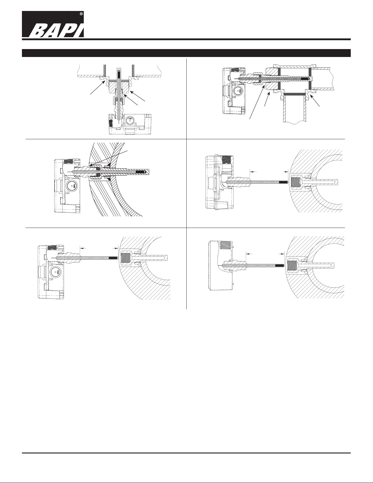
T-Pipe Fitting
Fig 10: Typical T-Mount
Fig 12: Typical Sensor Inserted
Per Order
Reducer
1/2 Inch NPT
Hand Tighten Into Well
1/2 Inch NPT
Fig 11: Typical Corner Mount
1. Insert
2. Hand Tighten
Fig 13: BAPI-Box (BB) Model Before Insertion
Per Order
Reducer
Per Order
T-Pipe Fitting
1. Insert
2. Hand Tighten
Fig 14: BAPI-Box 2 (BB2) Model Before Insertion
Fig 15: Weatherproof (WP) Sensor Before Insertion
1. Insert
2. Hand Tighten
Application: Figure 12 shows a typical thermowell and immersion probe installed into a pipe. In a properly insulated pipe
with liquid or steam, the temperature is essentially the same across the entire cross section of the pipe. Usually thermowells
are sized to extend to the center of the pipe; however, shorter thermowells will give proper temperature readings if properly
insulated. The shorter thermowells are used in pipes with high ow velocities. See Application notes “Thermowells Explained” on
our web site BAPIHVAC.com.
Thermowell Installer: Typically a Pipe Fitter drills a ¾-inch hole into the pipe where the thermowell is needed. A customer
provided tting, called a Threadolet or Weldolet, is welded to the pipe over the hole. The Threadolet has a ½” NPT thread in the
center. Thread sealant such as Teon tape or pipe dope is applied to the ½” NPT threads of the thermowell. The thermowell is
then inserted into the Threadolet and tightened. Estimates on insertion depths can be seen in our Application note “Thermowells
Explained” on our web site BAPIHVAC.com
Sensor Installation: Insert the immersion sensor into the well. Hand tighten the immersion sensor snugly without too much
torque. The probe is tight tting to the bottom and wall of the thermowell offering an accurate temperature reading.
Direct probe insertion into the pipe without a thermowell is possible. However, this is not recommended as it cannot be removed
after the pipe is pressurized. Apply a minimum of ve turns of Teon tap to the SS probe side threads. Insert the SS probe and
½” NPT threads into the Threadolet and tighten with a wrench to achieve a water tight seal. The probe should not touch the far
inside of the water pipe or probe failure may occur.
Specications subject to change without notice.
2 of 4
Page 3

Double Threaded Stainless Steel Immersion Transmitters
BA/T# -Ix-SS Temperature Transmitter
Installation & Operating Instructions
20919_ins_ImrsnDblThread_Active
Wiring & Termination
BAPI recommends using twisted pair of at least 22AWG and sealant lled connectors for all wire connections. Larger
gauge wire may be required for long runs. All wiring must comply with the National Electric Code (NEC) and local codes.
Do NOT run this device’s wiring in the same conduit as high or low voltage AC power wiring. BAPI’s tests show that inaccurate signal levels are possible when AC power wiring is present in the same conduit as the sensor wires.
rev. 06/30/15
Fig. 17: Typical
RTD 4 to 20mA
Transmitter with
Terminals
Fig. 18: Typical Thermistor
4 to 20mA Transmitter
Fig. 16: Typical
RTD 4 to 20 mA
Transmitter with
Flying Leads
Fig. 19: Typical Thermistor
Voltage Transmitter
Diagnostics
Possible Problems: Possible Solutions:
•
Unit will not operate. - Measure the power supply voltage by placing a voltmeter across the transmitter’s (+) and
- Check if the RTD wires are physically open or shorted together and are terminated to the
- Measure the physical temperature at the temperature sensor’s location using an accurate
(-) terminal. Make sure that it matches the drawings above and power requirements in the
specications.
transmitter.
temperature standard. Disconnect the temperature sensor wires and measure the
temperature sensor’s resistance with an ohmmeter. Compare the temperature sensor’s
resistance to the appropriate temperature sensor table on the BAPI web site.
• The reading is incorrect in the controller.
- For a 4-20mA current transmitter measure the transmitter current by placing an ammeter
Voltage Temperature Equation
T = TLow + (V x TSpan)
VSpan
T = Temperature at sensor
TLow = Low temperature of span
THigh = High temperature of span
TSpan = THigh - TLow
VLow = Low transmitter voltage
usually=(0, 1 or 2v)
VHigh = High transmitter voltage
usually=(5 or 10v)
VSpan = VHigh - VLow
V = Signal reading in volts
- Determine if the input is set up correctly in the controllers and BAS software.
in series with the controller input. The current should read according to the “4-20mA
Temperature Equation” shown below.
- For a voltage transmitter, measure the signal with a volt meter (Orange or Orange/Black to
Black). The signal should read according to the “Voltage Temperature Equation” shown below.
4-20mA Temperature Equation
T = TLow + (A -4) x (TSpan)
16
T = Temperature at sensor
TLow = Low temperature of span
THigh = High temperature of span
TSpan = THigh - TLow
A = Signal reading in mA
Specications subject to change without notice.
3 of 4
Page 4

20919_ins_ImrsnDblThread_Active
Specications
Double Threaded Stainless Steel Immersion Transmitters
BA/T# -Ix-SS Temperature Transmitter
Installation & Operating Instructions
rev. 06/30/15
RTD Transmitter
Power Required: 7 to 40VDC
Transmitter Output: 4 to 20mA, 850Ω@24VDC
Output Wiring: 2 wire loop
Output Limits: <1mA (short), <22.35mA (open)
Span:
Zero:
Min. 30ºF (17ºC), Max 1000ºF, (555ºC)
Min. -148°F (-100°C), Max 900ºF (482ºC)
Zero & Span Adjust: 10% of span
Accuracy: ±0.065% of span
Linearity: ±0.125% of span
Power Output Shift: ±0.009% of span
RTD Sensor: 2 wire Platinum (Pt), 385 curve
Transmitter Ambient -4 to 158ºF(-20 to 70ºC)
0 to 95% RH, Non-condensing
Thermistor Transmitter
Supply Voltage:
10 to 35 VDC (0 to 5 VDC or 4 to 20 mA Outputs)
15 to 35 VDC (0 to 10 VDC Output)
12 to 24 VAC (0 to 5 VDC Outputs)
15 to 24 VAC (0 to 10 VDC Output)
Transmitter Output: 4 to 20mA, 700Ω@24VDC
0 to 5 & 0 to 10VDC, 10KΩ min
Output Wiring: 2 & 3 wire (See wiring detail on pg. 3)
Transmitter Limits: -40 to 185ºF, (-40 to 85ºC)
Accuracy: ±1.015ºC, from (0 to 65ºC)
Linearity: ±0.065ºC, from (0 to 65ºC)
Resolution: Span/1024
Thermistor Sensor: 10K-2 Thermistor, 10KΩ @77ºF
Transmitter Ambient: 32 to 158ºF, (0º to 70ºC)
0 to 95% RH, Noncondensing
Thermistor:
10K-2, Thermal Resistor (Bare Sensor)
Accuracy (Std): ±0.36ºF, (±0.2ºC)
Accuracy (High): ±0.18ºF, (±0.1ºC), [XP] option
Stability: < 0.036ºF/Year, (<0.02ºC/Year)
Heat Dissipation: 2.7 mW/ºC
Probe Range: -40º to 221ºF (-40º to 105ºC)
Wire Colors:
Standard: Yellow/Yellow (no polarity)
High Acc. [XP]: Yellow/Yellow (no polarity)
RTD:
Resistance Temp Device (Bare Sensor)
Platinum (Pt): 100Ω and 1KΩ @0ºC, 385 curve,
Pt Accuracy (Std): 0.12% @Ref, or ±0.55ºF, (±0.3ºC)
Pt Accuracy (High): 0.06% @Ref, or ±0.277ºF,
(±0.15ºC), [A]option
Pt Stability: ±0.25ºF, (±0.14ºC)
Pt Self Heating: 0.4 ºC/mW @0ºC
Pt Probe Range: -40º to 221ºF, (-40 to 105ºC)
Wire Colors:
General color code (other colors possible)
1KΩ, Class B Orange/Orange (no polarity)
1KΩ, Class A Orange/White (no polarity)
100Ω, Class B Red/Red (no polarity)
100Ω, Class A Red/Red-w/black stripe (no polarity)
Sensitivity: Approximate @ 32ºF (0ºC)
Thermistor: Non-linear - (See www.bapihvac.com,
click “Sensor Specs”)
RTD (Pt): 3.85Ω/ºC for 1KΩ RTD
0.385Ω/ºC for 100Ω RTD
Lead Wire: 22awg stranded
Insulation: Etched Teon, Plenum rated
Probe Rigid: 316 Stainless Steel, 0.25” OD
Probe Length:
2’, 4’, 8’ or custom per order
Mounting: 1/2” NPT, 316 Stainless Steel Double
Threaded Fitting
Enclosure Types: (Part number designator in bold)
Weatherproof: -WP, w/ two ½” FNPT entries, (Bell box)
BAPI-Box: -BB, w/ four ½” NPSM & one ½” drill-out
BAPI-Box 2:
-BB2, w/ three ½” NPSM & three ½” drill-outs
Enclosure Ratings: (Part number designator in bold)
No Box: -NB, No Rating, (Probe Only)
Weatherproof: -WP, NEMA 3R, IP14
BAPI-Box: -BB, NEMA 4, IP66, UV Rated
BAPI-Box 2: -BB2, NEMA 4, IP66, UV Rated
Enclosure Material: (Part number designator in bold)
Weatherproof: -WP, Cast Aluminum, UV rated
BAPI-Box: -BB, Polycarbonate, UL94V-0, UV rated
BAPI-Box 2: -BB2, Polycarbonate, UL94V-0, UV rated
Ambient (Enclosure): 0 to 100% RH, Non-condensing
Weatherproof -WP, -40ºF to 212ºF, (-40º to 100ºC)
BAPI-Box -BB, -40ºF to 185ºF, (-40º to 85ºC)
BAPI-Box 2 -BB2, -40ºF to 185ºF, (-40º to 85ºC)
Agency: RoHS
PT= DIN43760, IEC Pub 751-1983,
JIS C1604-1989
Specications subject to change without notice.
4 of 4
 Loading...