

Page 1
9524_ins_therm_rtd_rm
Product Identication
Delta Style, BAPI-Stat 2 or BAPI-Stat 4 Room Units with
Thermistor, RTD or Semiconductor & No Setpoint, LCD or Override
Termination and Troubleshooting
rev. 06/24/15
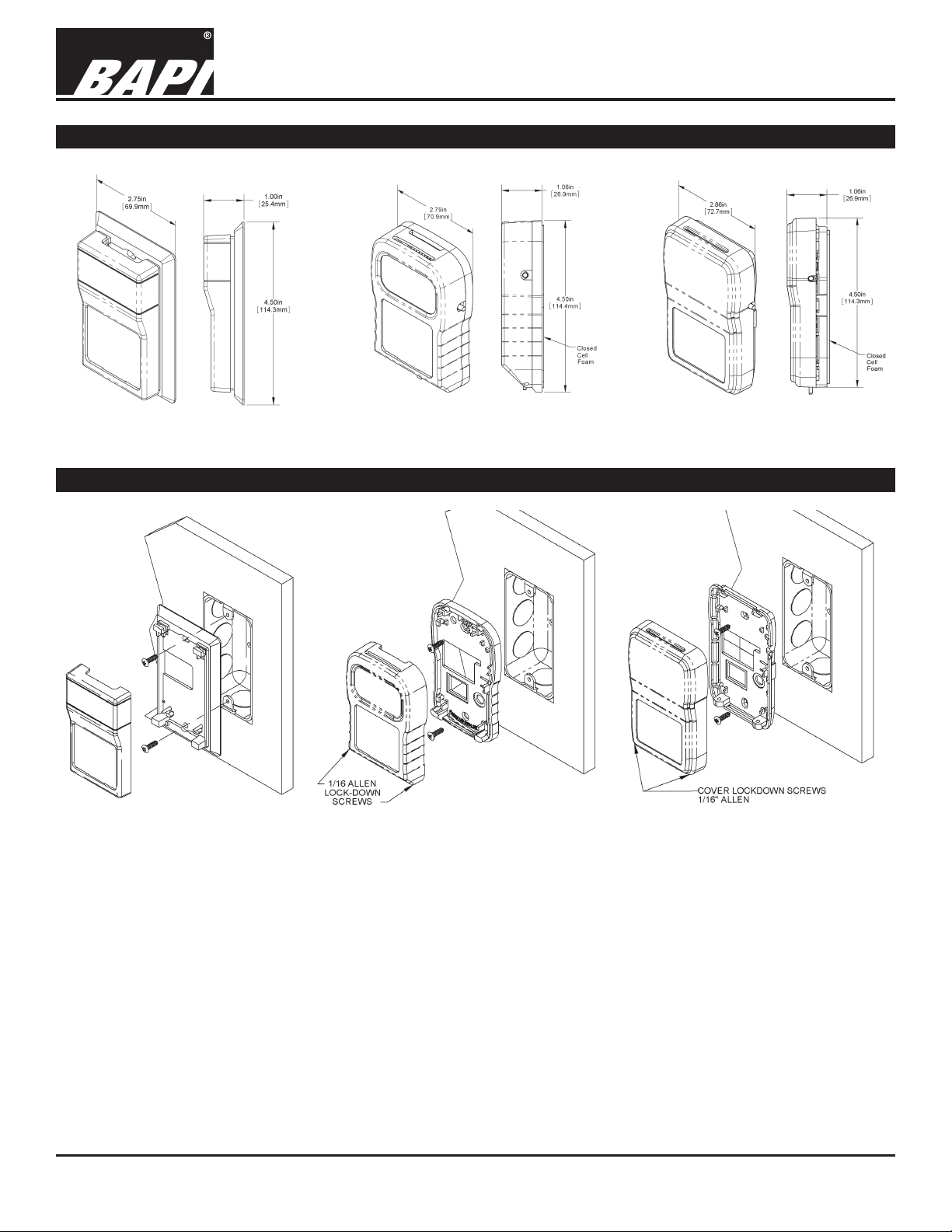
Fig. 1: Delta Style Fig. 2: BAPI-Stat 2
Mounting
Fig. 4:
Delta Style J-Box Mounting
Fig. 5:
BAPI-Stat 2 J-Box Mounting
Fig. 3: BAPI-Stat 4
Fig. 6:
BAPI-Stat 4 J-Box Mounting
Mounting hardware is provided for both junction box (J-box) and drywall installation (J-Box installation shown above).
JUNCTION BOX INSTRUCTIONS
1. Pull the wire through the wall and out of the junction box, leaving about six inches free.
2. Pull the wire through the hole in the base plate.
3. Secure the base to the box using the # 6-32 x 3/4 inch mounting screw provided.
4. Terminate the unit according to the guidelines in Termination on page 2.
5. Attach Cover by latching it to the top of the base, rotating the cover down and snapping it into place.
6. Secure the cover by backing out the lock-down screws using a 1/16” Allen wrench until they are ush with the bottom of the cover.
(Drywall Mounting Instructions are found on page 2)
Specications subject to change without notice.
1 of 3
Page 2
Delta Style, BAPI-Stat 2 or BAPI-Stat 4 Room Units with
Thermistor, RTD or Semiconductor & No Setpoint, LCD or Override
Termination and Troubleshooting
9524_ins_therm_rtd_rm
Mounting Continued
DRYWALL MOUNTING INSTRUCTIONS
1. Place the base plate against the wall where you want to mount the sensor.
2. Using a pencil mark out the two mounting holes and the area where the wires will come through the wall.
3. Drill two 3/16” holes in the center of each marked mounting hole. Insert a drywall anchor into each hole.
4. Drill one 1/2” hole in the middle of the marked wiring area.
5. Pull the wire through the wall and out of the 1/2” hole, leaving about six inches free.
6. Pull the wire through the hole in the base plate.
7. Secure the base to the drywall anchors using the #6 x 1 inch mounting screws provided.
8. Terminate the unit according to the guidelines in Termination on page 2.
9. Attach Cover by latching it to the top of the base, rotating the cover down and snapping it into place. Secure the cover
by backing out the lock-down screws using a 1/16” Allen wrench until they are ush with the bottom of the cover.
NOTE: In a wall-mount application, the wall temperature and the temperature of the air within the wall cavity can cause
erroneous readings. The mixing of room air and air from within the wall cavity can lead to condensation, erroneous readings and premature failure of the sensor. To prevent these conditions, seal the conduit leading to the junction box and seal
the hole in the drywall by using an adhesive backed, foam insulating pad (order part number BA/FOAMBACK-ROOM).
rev. 06/24/15
Termination
BAPI recommends using twisted pair of at least 22AWG and sealant lled connectors for all wire connections. Larger
gauge wire may be required for long runs. All wiring must comply with the National Electric Code (NEC) and local codes.
Do NOT run this device’s wiring in the same conduit as AC power wiring of NEC class 1, NEC class 2, NEC class 3 or with
wiring used to supply highly inductive loads such as motors, contactors and relays. BAPI’s tests show that uctuating and
inaccurate signal levels are possible when AC power wiring is present in the same conduit as the signal lines. If you are
experiencing any of these difculties, please contact your BAPI representative.
BAPI recommends wiring the product with power disconnected. Proper supply voltage, polarity, and
wiring connections are important to a successful installation. Not observing these recommendations may
damage the product and will void the warranty.
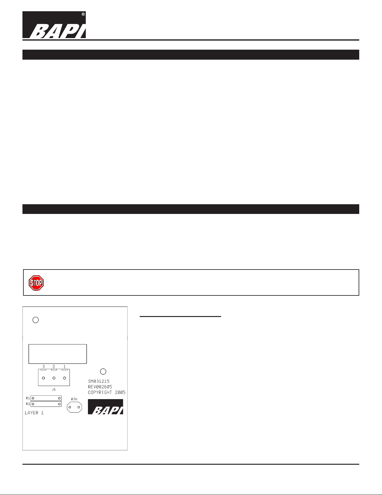
Sensor Termination
Pin 1 .....Sensor, To Analog Input of Controller
(Resistive Output)
Pin 2 .....Sensor, To Analog Input of Controller
(Resistive Output)
Pin 3 .....Not Used for Two Wire Sensors
(Three Wire Sensors use Pin 2 and Pin 3 as Common.
The odd wire connects to Pin 1.)
Fig 7:
Circuit Board for the Delta and
BAPI-Stat 2 Enclosures
Specications subject to change without notice.
2 of 3
Page 3

9524_ins_therm_rtd_rm
Diagnostics
Delta Style, BAPI-Stat 2 or BAPI-Stat 4 Room Units with
Thermistor, RTD or Semiconductor & No Setpoint, LCD or Override
Termination and Troubleshooting
rev. 06/24/15
POSSIBLE PROBLEMS:
General troubleshooting
Temperature reading is incorrect
POSSIBLE SOLUTIONS:
- Determine that the input is set up correctly in the controller software and
building automation software.
- Check wiring for proper termination
- Check for corrosion at either the controller or the sensor. Clean off the
corrosion, re-strip the interconnecting wire and reapply the connection. In
extreme cases, replace the controller, interconnecting wire and/or sensor.
- Label the terminals that the interconnecting wires are connected to at the
sensor end and the controller end. Disconnect the interconnecting wires from
the controller and the sensor. With the interconnecting wires separated at
both ends measure the resistance from wire-to-wire with a multimeter.
The
meter should read greater than 10 Meg-ohms, open or OL depending on the
meter you have. Short the interconnecting wires together at one end. Go to
the other end and measure the resistance from wire-to-wire with a multimeter.
The meter should read less than 10 ohms (22 gauge or larger, 250 feet or
less). If either test fails, replace the wire.
- Determine that the temperature sensors wires are connected to the correct
controller input terminals and are not loose.
- Check the wires at the sensor for proper connections.
- Measure the physical temperature at the temperature sensor’s location using
an accurate temperature standard. Disconnect the temperature sensor wires
and measure the temperature sensor’s resistance across the sensor output
pins with an ohmmeter. Compare the temperature sensor’s resistance to the
appropriate temperature sensor table on the BAPI website. If the measured
resistance is different from the temperature table by more than 5%, call
BAPI technical support. Find BAPI’s website at www.bapihvac.com; click on
“Resource Library” and “Sensor Specs”, then click on the type of sensor you
have. Don’t forget to reconnect the wires.
- Make sure that the sensor leads are not touching one another.
- Determine if the sensor is exposed to an external air source different from
room environment, such as a conduit draft. If so, ll the junction box with
berglass insulation or plug the conduit.
Specications
Environmental Operation Range:
Temperature: 32 to 122 oF (0 to 50 oC)
Humidity: 0 to 95%, non-condensing
Material: ABS Plastic
Material Rating: UL 94, HB
Agency: CE Compliant (
All Passive Thermistors 10KΩ and smaller are CE compliant.)
Specications subject to change without notice.
3 of 3
 Loading...