

Page 1
Decora Style Room Unit - BA/RuPD
Overview and Identication
The Decora Style Room Unit ts inside a Decora Style Wall Plate.
It features measurement and display of local temperature with
optional pushbutton setpoint adjustment.
The room temperature is shown on an easy-to-read LCD display
in either °F or °C (eld selectable via front pushbuttons for setpoint
models). The display can also be congured to show only the
setpoint.
Besides the standard wall plate cover, the unit is also available
with two styles of decorative wall plate covers: the “Curved” style
or “Dentil” style.
The sensor, selected at time of order, can be any BAPI passive
sensor. The sensor and setpoint outputs can be congured for
“common ground” or “differential” controller inputs, and the setpoint
is available as a resistance or a 0 to 5V output. The temperature
display can be offset in the eld as needed.
Installation and Operation Instructions
rev. 04/16/1818640_ins_RuPD
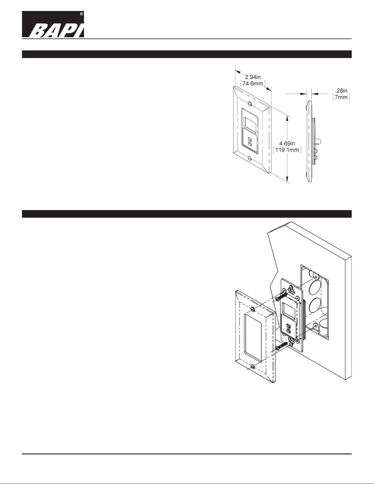
Fig 1: Decora Style Room Unit with
Standard Wall Plate Cover
Mounting
BAPI recommends that the Decora Style Room Unit only be installed
into a 2 X4 inch electrical box. Insulate the Decora Style Room Unit from
conduit drafts by lling the junction box with berglass or polyester ll
insulation. Do not pack the material into the junction box; leave it loose.
1. Pull the wire through the wall and out of the junction box,
leaving about six inches free.
2. Place the insulation into the junction box.
3. Terminate the unit according to the guidelines in
Termination on page 2.
4. Secure the sensor to the junction box using the #6-32 x 1/2 inch
mounting screws provided.
5. Secure the Decora trim plate to the sensor with the provided screws.
Fig 2: Decora Style
Room Unit Mounting
Note: Some plastic junction boxes do not have openings large enough to accept the Decora style room unit. Check
your junction boxes for proper t before installing.
Specications subject to change without notice.
1 of 3
Page 2
Decora Style Room Unit - BA/RuPD
Installation and Operation Instructions
rev. 04/16/1818640_ins_RuPD
Termination
BAPI recommends using twisted pair of at least 22AWG and sealant lled connectors for all wire connections. Larger
gauge wire may be required for long runs. All wiring must comply with the National Electric Code (NEC) and local codes.
Do NOT run this device’s wiring in the same conduit as AC power wiring of NEC class 1, NEC class 2, NEC class 3 or with
wiring used to supply highly inductive loads such as motors, contactors and relays. BAPI’s tests show that uctuating and
inaccurate signal levels are possible when AC power wiring is present in the same conduit as the signal lines. If you are
experiencing any of these difculties, please contact your BAPI representative.
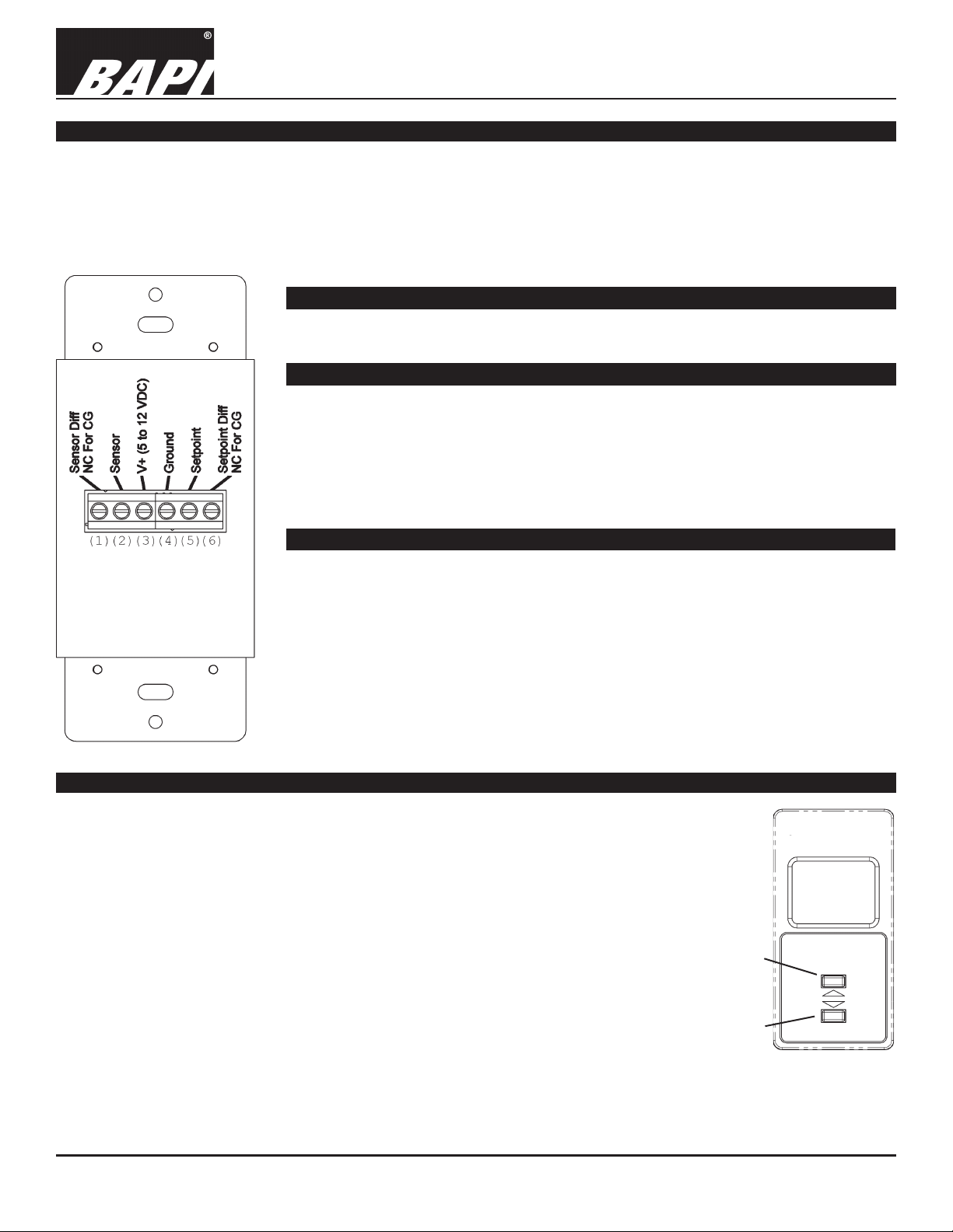
Terminal Function - For All Units
(3) V+ .................... 5 to 12 VDC Power
(4) Ground ............Connect to Ground, Common or GND
Terminal Function - For Common Ground Units
(1) Sensor Diff ......Not Used on Common Ground Units
(2) Sensor .............Temperature Output, Resistive, Connect to Controller Analog Input
(Reference to Ground)
(5) Setpoint ........... Setpoint Output, Resistive, Connect to Controller Analog Input
(Reference to Ground)
(6) Setpnt Diff .......Not Used on Common Ground Units
Terminal Function - For Differential Ground Units
(1) Sensor Diff ......Sensor Differential Temperature Output (-), Resistive
Fig 3:
Terminals on the
back of the Decora
Style Room Unit
Front Panel Adjustments
Setpoint Adjustment - The Decora Style Unit normally displays the temperature. To see the
current setpoint, press and release either “up” or “down” button. A small square will appear in
the lower left of the display and the setpoint will be shown. Press the “up” or “down” button to
change the setpoint. After about 10 seconds, the display will switch back to the temperature
(with the new setpoint stored). The setpoint will hold through power outages.
Temperature Offset - The temperature display may be offset to match the temperature
measured by the controller. Press both “up” and “down” buttons for 2 seconds. A small
square will appear in the lower left of the display and a single digit will display. Press the “up”
or “down” button to set the temperature display offset by ±10°. After about 10 seconds, the
display will switch back to the temperature (with the new offset stored). The offset will hold
through power outages.
Display Options - The unit’s display may be changed from room temperature Fahrenheit
(F), room temperature Celsius (C), Setpoint Only Fahrenheit (SF) or Setpoint Only Celsius
(SC). Press in both “up” and “down” buttons for 4 seconds. A small square will appear in the
lower left of the display and “F”, “C”, “SF” or “SC” will display. Press the “up” or “down” button
to toggle between the modes. After about 10 seconds, the unit will leave the program mode
and switch to the display that you’ve selected. The display selection will hold through power
outages.
Connect to controller Analog Input.
(2) Sensor .............Sensor Temperature Output (+), Resistive
Connect to Controller Analog Input
(5) Setpoint ........... Setpoint Output (+), Resistive, Connect to Controller Analog Input
(6) Setpnt Diff .......Setpoint Differential Output (-), Resistive
Connect to Controller Analog Input
Note: Terminal Reference ID’s in (Parentheses) are not on the product.
Up
Button
Down
Button
Fig 4:
Front of Decora
Style Room Unit
Specications subject to change without notice.
2 of 3
Page 3

Decora Style Room Unit - BA/RuPD
Installation and Operation Instructions
rev. 04/16/1818640_ins_RuPD
Diagnostics
The Display Is Not Working:
Check that the correct power is being supplied by measuring the DC voltage between the power terminals #3 (V+) and #4
(Ground). The power should be 5 to 12 VDC. Also check for proper polarity between the power terminals with (V+) at 5 to
12 VDC, and (Ground) as ground or common.
Inaccurate Temperature Sensor Reading:
Power down the unit and disconnect the wires from Terminals #2 and #4 on Common Ground Units (Terminals #1 and
#2 for Differential Ground Units). Measure the room temperature at the Decora sensor’s location using an accurate
temperature standard. Measure the temperature sensor’s resistance with an ohmmeter across terminals #2 and #4 on
Common Ground Units (Terminals #1 and #2 for Differential Ground Units). Compare this resistance to the appropriate
temperature sensor’s Output Table on the BAPI website (www.bapihvac.com; click on the button labeled “Sensor Specs”).
If the measured resistance is different from the Output Table by more than 5%, call BAPI technical support.
If the sensor’s resistance matches the Output Table as described above, then check the wiring between the sensor and
the controller. With the interconnecting wires disconnected at both ends, measure the resistance from wire-to-wire with
a multimeter. The meter should read greater than 10 Meg-ohms, open or OL depending on the meter you have. Short
the interconnecting wires together at one end. Go to the other end and measure the resistance from wire-to-wire with a
multimeter. The meter should read less than 10 ohms (22 gauge or larger, 250 feet or less). If either test fails, replace the
wire.
Note: Temperature errors can also be caused by drafts coming through the junction box behind the sensor. Seal the
junction box as described in the Mounting section on page 1. Mounting the Decora Style Sensor on an outside wall,
above radiator, directly below a vent, or in direct sunlight is not recommended.
Inaccurate or No Setpoint Output
Disconnect the setpoint wires from terminals #4 and #5 on Common Ground Units (Terminals #5 and #6 for Differential
Ground Units). Apply power to the Decora Style Sensor and measure the setpoint output from Terminals #4 and #5 on
Common Ground Units (Terminals #5 and #6 for Differential Ground Units). The Setpoint Output is printed on the label at
back of the unit and can be either a resistance or a voltage of 0 to 5V or 0 to 10V. Compare the measured reading to the
setpoint information on the label. If the measured reading is different from the label, call BAPI technical support.
If the measured Setpoint Output reading matches the label as described in the previous paragraph, then check the wiring
between the sensor and the controller as described in the “Inaccurate Temperature Sensor Reading” section above.
Specications
Power: 5 to 12 VDC, ±5%
Notes of Power:
Unit must be powered by at least 7 VDC to have the
0 to 5 Volt Setpoint Output Range Option
Unit must be powered by at least 12 VDC to have
the 0 to 10 Volt Setpoint Output Range Option
Power Consumption: 0.5 mA max.
Sensing Element: Thermistor or RTD
Wiring: 2 to 3 pair of 16 to 22AWG
Mounting: 2” by 4” J-box (screws provided)
Environmental Operation Range:
32 to 122°F (0 to 50°C)
0 to 95%RH, non-condensing
Material: ABS Plastic
Material Rating: UL94, V-0
LCD Display Range: 32 to 99°F, (0 to 35°C)
LCD Digits: 2 Digit; no decimal
LCD Height: 0.5” high
LCD Units: °F or °C at start-up
Specications subject to change without notice.
3 of 3
 Loading...