

Page 1
Duct and Rough Service Carbon Monoxide Sensor
34612_ins_CO_V_BB
Product Identication and Overview
BAPI’s Carbon Monoxide Sensor offers enhanced electrochemical sensing
with outstanding accuracy at low concentrations. The Duct unit samples duct
air using an aspiration tube. The Rough Service unit features a ventilated
BAPI-Box and is ideal for parking ramps, equipment rooms and warehouses.
The sensor has eld selectable CO ranges of 0 to 100, 0 to 200, 0 to 300 and
0 to 500 ppm. It also has eld selectable outputs of 0 to 5, 1 to 5, 0 to 10, 2 to
10 VDC and 3-wire 4 to 20 mA output. The large LCD is backlit for 10 seconds
after any button push.
Two independent SPDT alarm contacts switch at eld selectable CO
concentrations of 25, 35, 50, 100 and 200 ppm. An alarm timer can hold the
output relays on for one to ten minutes after the CO level has fallen below
80% of setpoint. This allows additional fan run time to be sure that the CO
has been purged. The eld replaceable sensor element lasts approximately 7
years and is self tested daily.
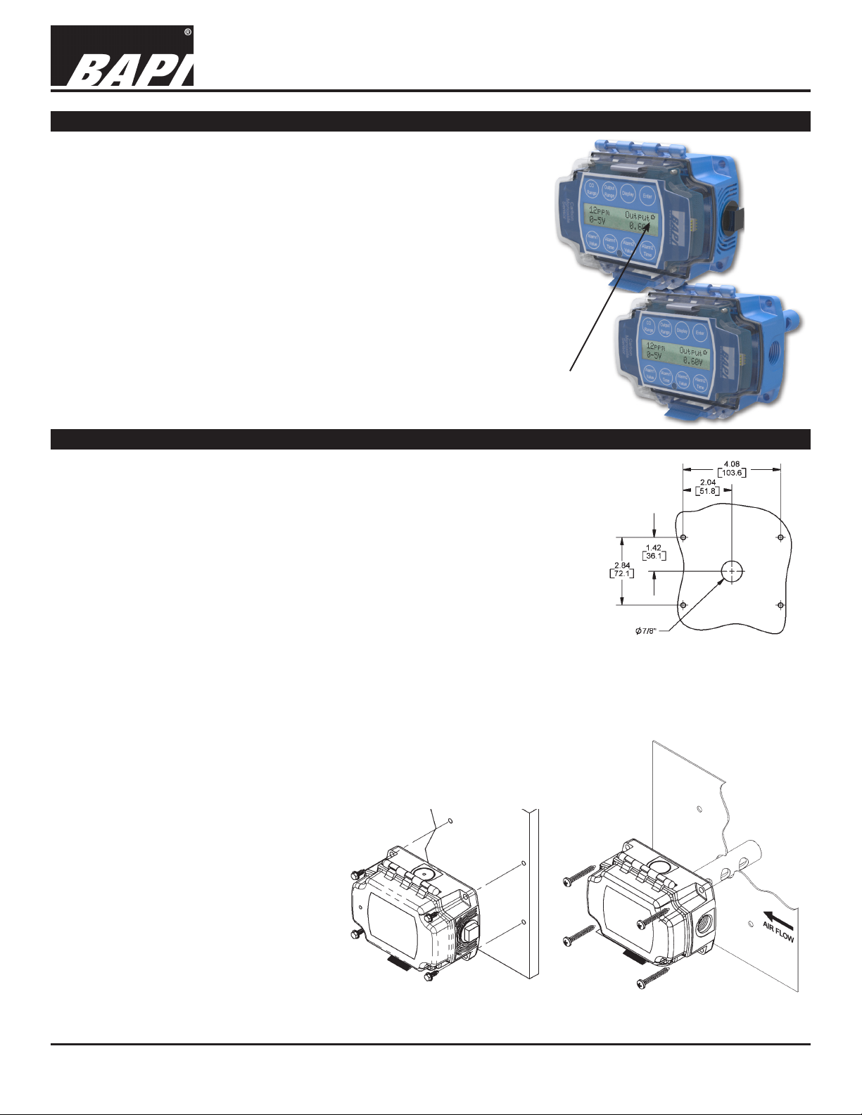
Note: There is a small heart symbol in the top right corner of the display that blinks
every ½ second. This heartbeat indicates that the unit is operating correctly.
Mounting
Installation & Operating Instructions
rev. 10/11/17
Rough
Service
(top)
and
Duct CO
Sensors
Rough Service Ventilated Unit
1. Mount the unit on a solid, non-vibrating surface 3 to 5 feet above oor level. Mount
in a horizontal orientation with the enclosure hinge at the top as shown in Fig 2.
Failure to do so may degrade the life of the sensor element. Do not mount near
supply or return diffusers.
2. Use BAPI recommended #10 (M5) screws on the four mounting feet of the
enclosure. A pilot-hole makes mounting easier. Use the enclosure mounting feet to
mark the pilot-hole locations.
3. Snug up the screws so that the foam backing is depressed but do not over-tighten
or strip the screw threads.
4. Place the provided #6 screws into the holes on each site of the lid latch to make the
cover tamper resistant.
Duct Aspiration Tube Unit
1. BAPI recommends placing the sensor in the middle of the duct wall, away from
stratied air, to achieve the best reading. The unit should also be a minimum of 3
duct diameters from an elbow, damper or other duct restriction.
2. Drill a 1” hole for the aspiration probe. Position the box so that airow is directly into
the holes on one side of the aspiration probe. The air direction is not important.
4. Mount the enclosure to the duct using
BAPI recommended #10 screws
through a minimum of two mounting
feet on opposite corners. A 1/8” pilot
hole makes mounting easier. Use the
mounting feet to mark the pilot-hole
locations.
5. Snug the screws until the foam backing
is compressed about 50% to prevent
air leakage but do not over-tighten.
6. Use the provided #6 screws to secure
the cover for IP66 rating.
7. BAPI recommends sealing the conduit
opening with berglass insulation.
Specications subject to change without notice.
Fig. 2: Rough Service
Unit mounting
Fig. 1: Screw Hole Template.
Drill center 7/8” hole for rear
conduit entry on Rough Service
Unit. Drill 1” hole for Aspiration
Tube on Duct Unit
Fig. 3: Duct Unit mounting
1 of 10
Page 2
Duct and Rough Service Carbon Monoxide Sensor
Installation & Operating Instructions
34612_ins_CO_V_BB
Termination
BAPI recommends using twisted pair of at least 22AWG and sealant lled connectors for all wire connections. Larger gauge
wire may be required for long runs. All wiring must comply with the National Electric Code (NEC) and local codes.
Do NOT run this device’s wiring in the same conduit as AC power wiring of NEC class 1, NEC class 2, NEC class 3 or with
wiring used to supply highly inductive loads such as motors, contactors and relays. BAPI’s tests show that uctuating and
inaccurate signal levels are possible when AC power wiring is present in the same conduit as the signal lines. If you are
experiencing any of these difculties, please contact your BAPI representative.
BAPI recommends wiring the product with power disconnected. Proper supply voltage, polarity and wiring
connections are important to a successful installation. Not observing these recommendations may damage the
product and void the warranty.
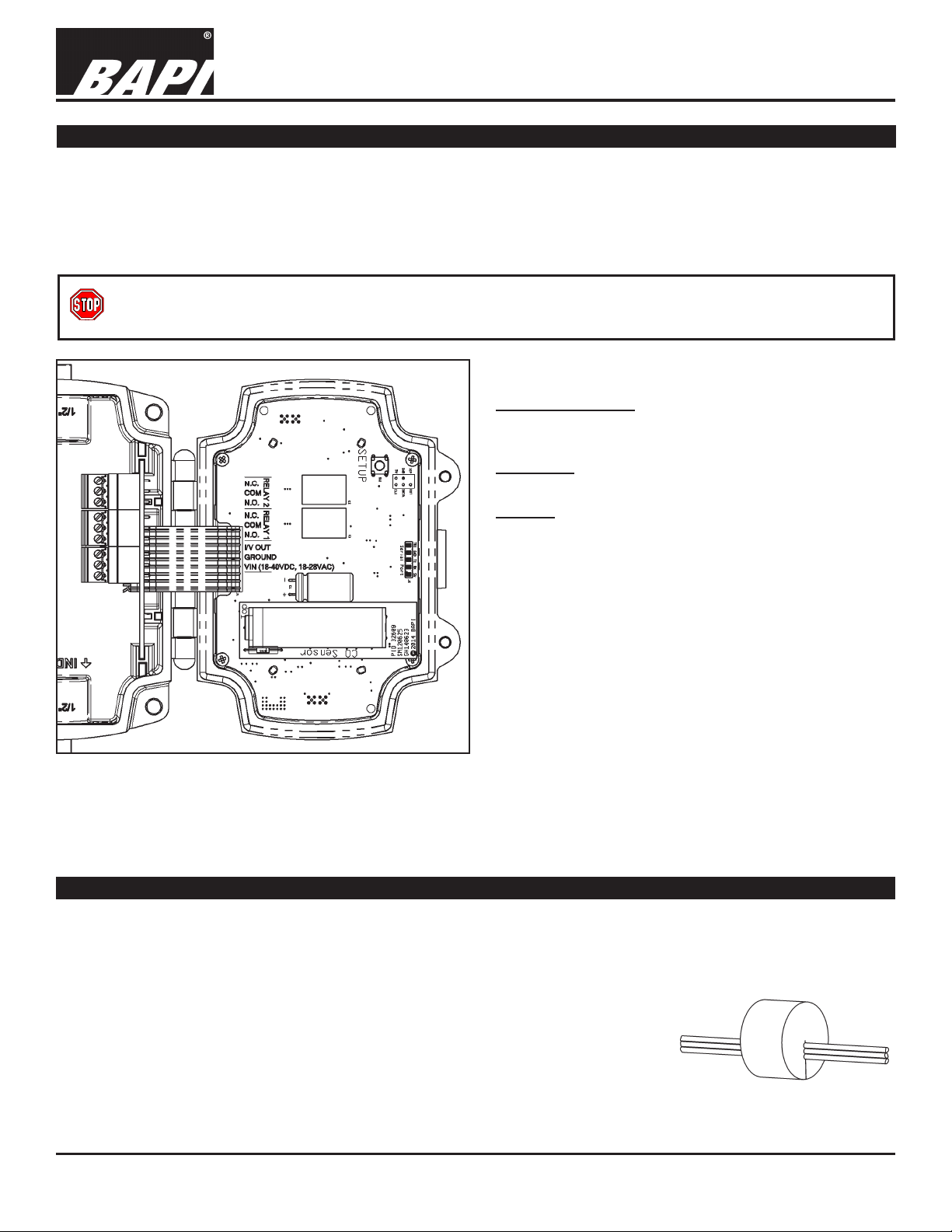
WIRING TERMINALS
VIN – Input Power
18 to 28 VAC, 7.2 VA Max
18 to 40 VDC, 180 mA Max.
GROUND:
N.C.
COM
N.O.
N.C.
COM
N.O.
OUT
GND
VIN
Power and Analog Output Ground
I/V OUT
Three wire voltage or current signal
RELAYS
Relay contacts are galvanically isolated. They are
not connected to each other, or to circuit power or
ground in the carbon monoxide transmitter.
N.O. – Normally Open Contact
COM – Common Contact
N.C. – Normally Closed Contact
rev. 10/11/17
Fig. 4: Field Wiring Terminals
NOTE: The connectors that plug into the jacks on the board use a rising block screw terminal to hold the wires. If the
block is in a partially up position, the wire may be inserted under the block and the wire will not be held when the screw
is tightened. To avoid improper wiring, turn the male connector screws counterclockwise until the block is below the wire
opening before inserting the wire. Lightly tug on each wire after tightening to verify proper termination.
Keeping the Enclosure Air Tight After Termination
For the sensor to work correctly, the wiring entrance must remain air tight. If the CO transmitter is mounted to
a hollow wall and wired through its back, or wired with conduit, it is possible that a draft of clean air may ll the
enclosure through the wiring opening. This draft may prevent the unit from measuring ambient Carbon Monoxide.
BAPI recommends either a liquid-tight tting or plugging the conduit at the enclosure.
• Liquid-Tight Fitting – BAPI’s Liquid-Tight Fitting (BA/LTF) allows wire cables
of 0.1 to 0.3 inch outside diameter to enter the box. Tightening the collar onto the
wire cable keeps the wiring entrance air tight.
• Conduit – Included with the Carbon Monoxide transmitter is a foam plug to seal
the ½ inch EMT. Place the wires into the plug as shown in Fig. 5 and then insert
the plug into the conduit sealing the conduit.
Fig. 5:
Wires Through Foam Plug
Specications subject to change without notice.
2 of 10
Page 3
Duct and Rough Service Carbon Monoxide Sensor
Installation & Operating Instructions
34612_ins_CO_V_BB
Relay Load Termination
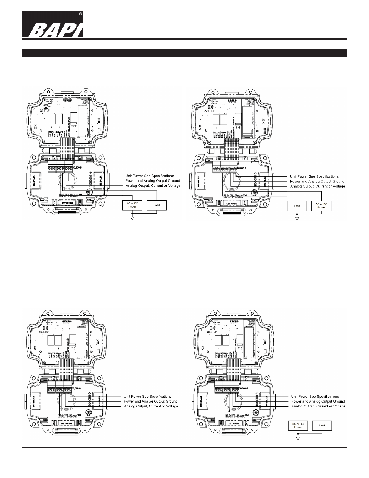
The Alarm Relays may be used to switch a load on or off. Fig. 6 shows a circuit that may be used to switch on a
load under alarm conditions. Fig. 7 shows a circuit that may be used to switch off a load under alarm conditions.
For clarity only Alarm Relay 1 is shown, Alarm Relay 2 may be used in the same way.
Fig. 7:
Fig. 6:
Turn “On”
a load
under alarm
conditions
Turn “Off”
a load
under alarm
conditions
rev. 10/11/17
Fig. 8 shows how two or more Carbon Monoxide Transmitters may be interconnected to switch a load. This example
shows how to turn on a load under alarm conditions. Similar circuitry may be used to turn off a load under alarm
conditions. Fig. 8 connects together the Normally Open terminals of Alarm Relay #1 in both units and connects them
to the load. Fig. 8 also connects together the Common terminals of Alarm Relay #1 in both units and then connects
them to the load’s power. This wiring circuit will drive the load whenever any one of the Carbon Monoxide Transmitters is in an alarm condition. Note: Be sure to only connect similar terminals from each unit (Normally Open terminal
to Normally Open terminal, etc.). Cross connecting any of the terminals (Normally Closed to Common, etc.) may
damage the units and may void the warranty.
For clarity only Alarm Relay 1 is shown in the example below. Alarm Relay 2 may be used in the same way.
Fig. 8:
Turn “On” a
load when
either unit
enters an alarm
condition
Specications subject to change without notice.
3 of 10
Page 4

Duct and Rough Service Carbon Monoxide Sensor
Installation & Operating Instructions
34612_ins_CO_V_BB
Relay Load Termination continued...
Some circuits require a switched ground to operate, such as audible alarms, visual alarms, or large AC motor controllers. Fig. 9 shows how to apply ground under an alarm condition. Fig. 10 shows how to remove ground under
an alarm condition. For clarity only Alarm Relay 1 is shown. Alarm Relay 2 may be used in the same way.
rev. 10/11/17
Fig. 9:
Applying
ground
under alarm
conditions
Fig. 10:
Removing
ground
under alarm
conditions
Power Up
During the rst 60 seconds after applying power, the Carbon Monoxide Transmitter performs the following functions:
• Front panel capacitive button test;
• Displays the transmitter’s software version number;
• Displays the transmitter’s serial number;
• Displays the transmitter’s run time;
• Displays the CO Module’s software version number;
• Displays the CO Module’s serial number;
• Displays the CO Module’s run time;
• Performs a CO Module self-test;
When the CO Module self-test is complete, the transmitter is operational.
Operation
The eight buttons
on the face of the
unit sense the user’s
ngertip when pressed
against the plastic
cover. The buttons
allow the user to
review or select
unit conguration
parameters. The top
line of the display
continues to show
the CO measurement
when reviewing or
selecting parameters.
Parameter Button Function
Review or select Carbon Monoxide measurement range used for analog output
Review or select analog output range
Review or select display on or display off
View hidden values, verify edit mode, save edited configuration parameters, or end configuration parameter edit
Review or select CO concentration to enable Alarm 1 relay
Review or select number of minutes that Alarm 1 relay stays on after CO dissipates
Review or select CO concentration to enable Alarm 2 relay
Review or select number of minutes that Alarm 2 relay stays on after CO dissipates
Specications subject to change without notice.
4 of 10
Page 5

Duct and Rough Service Carbon Monoxide Sensor
Installation & Operating Instructions
34612_ins_CO_V_BB
Operation continued...
Display On and Display Off Modes
The top line of the display shows the CO measurement when the Display Mode is set to “On” . If the Display Mode
is set to “Off,” the top line of the display shows the word “On” rather than the CO measurement. If the CO measurement is below Alarm 1 or Alarm 2 levels, the LED will be green.
Fig. 11:
Display During
Normal Operation
(Reading is below
CO alarm value)
rev. 10/11/17
Display “On” Mode
Display “Off” Mode
Displaying the CO Measurement, Analog Output Range and Analog Output Value
Touching the Enter button displays the Current Reading, the Analog Output Range and Analog Output Value for 10
seconds. The current reading is replaced by the word “On” if the display is set to “Off”.
4 to 20 mA Output Mode
(Display set to “On”)
Fig. 12: Display showing the Current Reading, the Analog Output Range and Analog Output Value
0 to 5 Volt Output Mode
(Display set to “On”)
0 to 5 Volt Output Mode
(Display set to “Off”)
CO Sensor Failure Display
The CO sensor element is tested for proper operation daily. If
the sensor fails:
• The top line of the display displays “Replace Sensor,”
• The analog output is set to 100% of range
• Both relays turn on,
• The LED ashes yellow.
Note: The sensor failure display is the same whether the
display is set to “On” or “Off”.
Specications subject to change without notice.
Fig. 13: CO Sensor Failure
5 of 10
Page 6

Duct and Rough Service Carbon Monoxide Sensor
34612_ins_CO_V_BB
Operation continued...
Alarm Condition 1 Display
If the CO measurement exceeds the
Alarm 1 setpoint:
• The CO measurement or the word
“On” is displayed on the rst line
• The alarm condition is display on
the second line
• The LED will be red
• The backlight ashes
Alarm Condition 2 Display
If the CO measurement exceeds the
Alarm 2 setpoint;
• The CO measurement or the word
“On” is displayed on the rst line
• The alarm condition is displayed on
the second line
• The LED will be red
• The back light ashes
Note: The Alarm 2 Setpoint may be
equal to, greater than or less than the
Alarm 1 Setpoint.
Installation & Operating Instructions
rev. 10/11/17
Alarm Condition 1
(Display set to “On”)
Fig. 14: Display when the measurement exceeds Alarm Condition 1 Setpoint
Alarm Condition 2
(Display set to “On”)
Fig. 15: Display when the measurement exceeds Alarm Condition 2 Setpoint
Alarm Condition 1
(Display set to “0ff”)
Alarm Condition 2
(Display set to “Off”)
Alarm Condition 1 & 2 Display
If the CO measurement exceeds the
Alarm 1 & 2 setpoint;
• The CO measurement or the word
“On” is displayed on the rst line
• The alarm condition 1 and 2 is
displayed on the second line
• The LED will be red
• The back light ashes
Note: The Alarm 2 Setpoint may be
equal to, greater than or less than the
Alarm 1 Setpoint.
Alarm Condition 1 & 2
(Display set to “On”)
Fig. 16: Display when the measurement exceeds Alarm
Condition 1 & 2 Setpoint
Specications subject to change without notice.
Alarm Condition 1 & 2
(Display set to “Off”)
6 of 10
Page 7

Duct and Rough Service Carbon Monoxide Sensor
Installation & Operating Instructions
34612_ins_CO_V_BB
Reviewing Parameter Settings
You can review the parameter settings at any time during normal operation by touching any of the eight buttons on
the face of the unit. The following gures show a typical display when a button is touched. The values will display for
10 seconds and then the display will revert to normal.
rev. 10/11/17
CO Range Output Range (0 to 10 Volts)
Display Mode Alarm 1 Value
Output Range (4 to 20mA)
Alarm 1 Time
Alarm 2 Value Alarm 2 Time
Specications subject to change without notice.
7 of 10
Page 8

Duct and Rough Service Carbon Monoxide Sensor
Installation & Operating Instructions
34612_ins_CO_V_BB
Parameter Setup and Default Settings
If eld personnel wish to change any parameter settings, they must remove the tamper resistant screws, open the
cover, and press the switch on the board labeled “Setup.” Follow Fig. 17 below to change parameters.
rev. 10/11/17
Fig. 17:
Parameter Setup Flow Chart
(Default settings are shown with gray shading)
Specications subject to change without notice.
8 of 10
Page 9

Duct and Rough Service Carbon Monoxide Sensor
34612_ins_CO_V_BB
Calibration
Every BAPI Carbon Monoxide Transmitter is factory calibrated. Each unit
is ready for operation after installation and the 60 second start-up time.
BAPI’s factory calibrated CO sensing element is not capable of eld
calibration. BAPI recommends replacing the sensor whenever the
Replace Sensor alarm is active, or every 7 years, or at the recalibration
intervals required by the local jurisdiction. The sensing element comes
supplied factory equipped with calibration certicate.
To replace the CO Module (Fig. 18), follow these steps;
• Remove the tamper resistant screws and open the lid
• Unplug the power connector
• For the next two steps, hold the sensor by the body, not the endcaps.
• Remove the CO Module by pulling it straight off the transmitter
• Plug in the new sensor by pushing the sensor board straight into the
transmitter
• Plug in the power connector
• Close the lid until it clicks, and replace the tamper resistant screws
Installation & Operating Instructions
rev. 10/11/17
Maintenance
The BA/CO sensor/transmitter unit should be vacuumed clean once a year
or more, depending on the rate of accumulation of any dust or dirt. T
o
avoid sensor damage, the unit MUST NOT be submerged in any liquids.
Hosing or splashing of the unit with any liquids must also be avoided and
may void the warranty.
The sensor in the Carbon Monoxide Transmitter typically has a life of over
Inserting or Removing the
Fig. 18:
Sensor Module
7 years. When the sensor reaches the end of its useful life, the transmitter
will alarm when a replacement is required. Factory calibrated replacement sensors are available from BAPI.
Specications
Power:
18 to 28 VAC, 7.2 VA Max
18 to 40 VDC, 180 mA Max
Field Selectable Ranges:
0 to 100, 0 to 200, 0 to 300 & 0 to 500 ppm
Sensor Element Life: 7 Years Typical
Alarm Relays:
2 Independent, Dry SPDT (Form C)
2 Amps at 24 VAC/DC, Resistive
140 VA Inrush, 48 VA Holding at 24 VAC
Field Wiring Terminals:
Pluggable Screw Terminals, 14 to 24 AWG
Response Time:
Alarm Relay Setpoints:
25, 35, 50, 100 or 200 ppm
Alarm Timer: 0, 1, 5 & 10 minutes
Field Selectable Outputs:
3-wire 4 to 20 mA
0 to 5 VDC, 1 to 5 VDC
0 to 10 VDC, 2 to 10 VDC
Accuracy:
<200ppm = ±3% FS, 32 to 122°F (0 to 50°C)
201 to 500 ppm = ±5% FS, 50 to 122°F (10 to 50°C)
Environmental Operation Range
14 to 122°F (-10 to 50°C)
5 to 95%RH Noncondensing
<80 seconds from 10% to 90% of range
See BAPI’s Application Notes on our website for further information about coverage area and mounting. Go to
www.bapihvac.com and select “Resource Library”. Click on “Application Notes”, then “Air Quality Related”, and choose
the link titled “Coverage Area and Mounting Recommendations for BAPI Indoor Air Quality Sensors”.
Specications subject to change without notice.
9 of 10
Page 10

34612_ins_CO_V_BB
Diagnostics
POSSIBLE PROBLEMS:
General troubleshooting
Duct and Rough Service Carbon Monoxide Sensor
Installation & Operating Instructions
rev. 10/11/17
POSSIBLE SOLUTIONS:
- Determine that the input is set up correctly in the controller’
automation software.
- Check wiring for proper termination
- Check for corrosion at either the controller or the sensor. Clean off the corrosion,
re-strip the interconnecting wire and reapply the connection. In extreme cases,
replace the controller, interconnecting wire and/or sensor.
- Label the terminals that the interconnecting wires are connected to at the sensor
end and the controller end. Disconnect the interconnecting wires from the
controller and the sensor. With the interconnecting wires separated at both ends,
measure the resistance from wire-to-wire with a multimeter. The meter should read
greater than 10 Meg-ohms, open or OL depending on the meter you have. Short
the interconnecting wires together at one end. Go to the other end and measure
the resistance from wire-to-wire with a multimeter. The meter should read less than
10 ohms (22 gauge or larger, 250 feet or less). If either test fails, replace the wire.
s and building
Unit does not operate
- Cycle power.
- Check power for proper polarity.
- Disconnect the power wires at the controller and measure the voltage coming
from the power source. If the voltage is outside the limits specied on page 1,
troubleshoot the power source. Reconnect power wires to controller when nished
- Disconnect the power wires at the sensor and measure the wires for the same
voltage as at the controller. If the voltage is different from that measured at the
source, troubleshoot the wire. Reconnect power wires to sensor when nished.
- Measure the power at the sensor with the power wires connected to the power
source. If the voltage is outside the limits specied on page 9, call your BAPI
representative.
ADDITIONAL DISPLAY MESSAGES AND INDICATION
Display Message LED Indication
Module not found
retrying
mA Output Fault Flashing Red
V Output Fault Flashing Red
Replace Sensor Flashing Yellow Sensor Module failed self-test, replace the sensor module
Self-Test Solid Yellow Sensor Module is performing a self-test
Solid Red Sensor Module is loose or missing. Securely plug in a sensor module
Unit is configured for mA output, but the loop resistance is incorrect.
Troubleshoot connection.
Unit is configured for voltage output, but the output voltage is incorrect.
Troubleshoot connection
Note: If you are experiencing any other problems besides those decribed above, contact your BAPI representative.
Specications subject to change without notice.
10 of 10
 Loading...