

Page 1
4
*
BA/RSOC-UNI-8
T ermination and Troubleshooting
10663_ins_uni8_rsoc
rev.
Termination
BAPI recommends using twisted pair of at least 22AWG and sealant filled connectors for all wire connections. Larger
gauge wire may be required for long runs. All wiring must comply with the National Electric Code (NEC) and local codes.
Do NOT run this device’s wiring in the same conduit as AC power wiring of NEC class 1, NEC class 2, NEC class 3 or with
wiring used to supply highly inductive loads such as motors, contactors and relays. BAPI’s tests show that fluctuating and
inaccurate signal levels are possible when AC power wiring is present in the same conduit as the signal lines. If you are
experiencing any of these difficulties, please contact your BAPI representative
BAPI does not recommend wiring the sensor with power applied as accidental arcing may
damage the product and will void the warranty
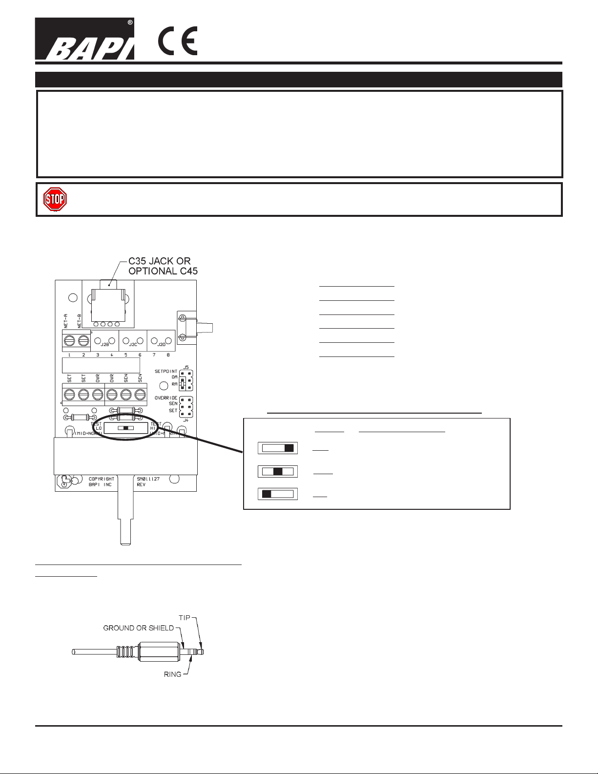
Fig 1
Wire Connections:
T erminal Blocks 1-8 (See Comm Jack wiring below)
Setpoint (Resistive Output)[T o Analog Input of Controller]
Setpoint (Resistive Output)[T o Analog Input of Controller]
Override (Resistive Output)[T o Analog Input of Controller]
Override (Resistive Output)[T o Analog Input of Controller]
Sensor (Resistive Output)[T o Analog Input of Controller]
Sensor (Resistive Output)[T o Analog Input of Controller]
9/13/0
Communications Jack: Standard: C35 3.5mm
Optional: C45
Fig. 2 C35
Male Jack shown for clarity
OPTIONAL TEST & BALANCE SWITCH
Optional: Test and Balance Switch (S2)
High: Will set the sensor value to highest temperature
Norm: Thermistor/RTD will operate normally
Low: Will set the sensor value to lowest temperature
C35 Wiring
NE T- A 1 [Internally connected to Comm Jack GROUND]
NE T - B 2 [Internally connected to Comm Jack TIP]
3 Not Connected
4 Not Connected
5 Not Connected
6 Not Connected
7 Not Connected
8 Not Connected
Note: Ring is not connected
*Some items may not be CE compliant, call BAPI for additional information.
Specifications subject to change without notice.
1
Page 2
10663_ins_uni8_rsoc
4
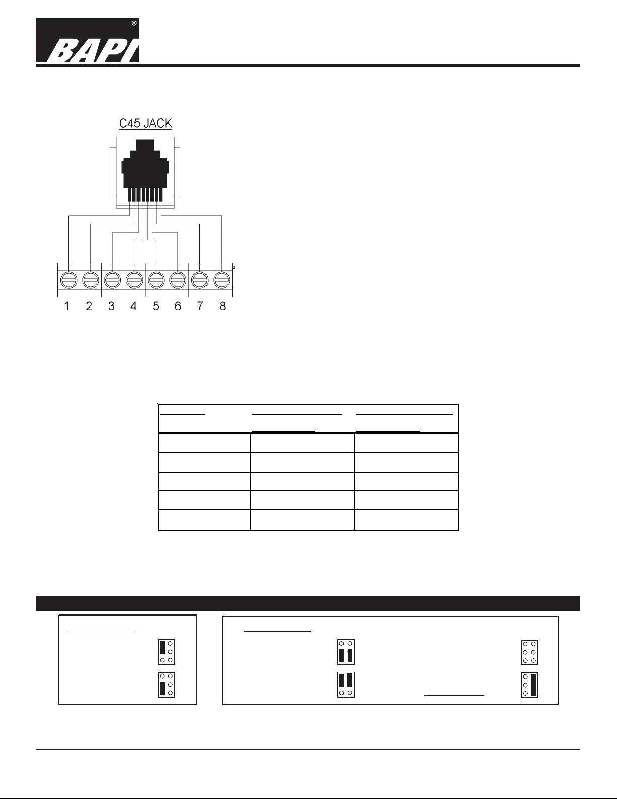
Fig. 3
BA/RSOC-UNI-8
T ermination and Troubleshooting
C45 Wiring
1 [Internally connected to Comm Jack pin 1]
2 [Internally connected to Comm Jack pin 2]
3 [Internally connected to Comm Jack pin 3]
4 [Internally connected to Comm Jack pin 4]
5 [Internally connected to Comm Jack pin 5]
6 [Internally connected to Comm Jack pin 6]
7 [Internally connected to Comm Jack pin 7]
8 [Internally connected to Comm Jack pin 8]
rev.
9/13/0
Jumper Settings
‘J5’ Options
Setpoint Direct
Acting (DA): J5=
Setpoint Reverse
Acting (RA): J5=
Sensor Type Low Temperature (40° F) High Temperature (105° F)
Resistance Value Resistance Value
1000Ω RTD 1.02KΩ (41.2°F) 1.15KΩ (101.5°F)
3000Ω Thermistor 7.87KΩ (39.5°F) 1.5KΩ (106.8°F)
10K-2 Thermistor 30.1KΩ (39.2°F) 4.75KΩ (105.8°F)
10K-3 Thermistor 26.7K
10K-3(11K) Thermistor 7.32KΩ (43.7°F) 3.65KΩ (105.2°F)
Ω
(35.9°F) 5.11KΩ (108.4°F)
‘J4’ Options
Override in parallel
with setpoint: J4=
Override in parallel
with sensor: J4=
Override as a
separate input: J4=
Common Ground
J2-Pins 2,4,6: J4=
Specifications subject to change without notice.
2
Page 3

BA/RSOC-UNI-8
4
T ermination and Troubleshooting
10663_ins_uni8_rsoc
Optional Bi-Metal Displays (Can not be used with RJ45 Comm Jack)
rev.
9/13/0
Celsius Display
10 15 20 25 30
Troubleshooting
Possible Problems:
Controller reports higher than actual temperature
Controller reports lower than actual temperature
Fahrenheit Display
50 60 70 80 90
Possible Solutions:
- Confirm the input is set up correctly in the front end software
- Verify that the wires are not physically shorted
- Check wiring for proper termination
- Verify the “Sensor” output is correct from “SEN” to “SEN”
- Confirm the input is set up correctly in the front end software
- Verify that the thermistor is not physically open
- Check wiring for proper termination
- Verify the “Sensor” output is correct from “SEN” to “SEN”
Setpoint is not working correctly
Override is not working correctly
- Verify the “Setpoint” output is correct from “SET” to “SET”
- Check wiring for proper termination
- Confirm the thermistor is not damaged
- Verify the output from “OVR” to “OVR” is less than 50 ohms
when override button is used
- Check wiring for proper termination
Specifications subject to change without notice.
3
Page 4

10663_ins_uni8_rsoc
4
Mounting
Fig. 2
BA/RSOC-UNI-8
T ermination and Troubleshooting
9/13/0
rev.
Mounting hardware is provided for both junction box and drywall installation (junction box installation shown).
Junction Box
1. Pull the wire through the wall and out of the junction box, leaving about six inches free.
2. Pull the wire through the hole in the base plate.
3. Secure the backplate to the box using the #6-32 x 1/2 inch mounting screw provided.
4. Terminate the unit according to the guidelines in Termination on p age 1.
5. Attach Cover by latching it to the top of the base, rotating the cover down and snapping it into place.
6. Secure the cover by backing out the lock-down screws using a 1/16" allen wrench until they are flush with the bottom
of the cover.
Drywall Mounting
1. Place the base plate against the wall where you want to mount the sensor.
2. Using a pencil mark out the two mounting holes and the area where the wires will come through the wall.
3. Drill two 3/16" holes in the center of each marked mounting hole. Insert a drywall anchor into each hole.
4. Drill one 1/2" hole in the middle of the marked wiring area.
5. Pull the wire through the wall and out of the 1/2" hole, leaving about six inches free.
6. Pull the wire through the hole in the base plate.
7. Secure the base to the drywall anchors using the #6 x 1 inch mounting screws provided.
8. Terminate the unit according to the guidelines in Termination on page 1.
9. Attach cover by latching it to the top of the base, rotating the cover down and snapping it into place.
10. Secure the cover by backing out the lock-down screws using a 1/16" allen wrench until they are flush with the bottom
of the cover.
NOTE
In a wall-mount application, the wall temperature and the temperature of the air within the wall cavity can cause erroneous
readings. The mixing of room air and air from within the wall cavity can lead to condensation, erroneous readings and
premature failure of the sensor.
T o prevent these conditions, seal the conduit leading to the junction box and seal the hole in the drywall by using an
adhesive backed, foam insulating pad(order part number BA/FOAMBACK).
Specifications subject to change without notice.
4
 Loading...