

Page 1

BAPI-Stat “Quantum Prime” Temp & Humidity Sensor
Overview and Identication
The BAPI-Stat “Quantum Prime” is designed for operating rooms,
clean rooms and elder care facilities. It features a large display
and membrane keypad for wipedown cleaning. It is available with
temperature and humidity measurement, temperature and humidity
setpoint and occupant override.
The unit includes a number of eld adjustments including °F or °C
display, temperature and humidity offset and setpoint lockout. The
display can also be set to show a large temperature and small %RH
reading or a large %RH and a small temperature reading when
4 buttons are present. This unit can be congured with up to four
transmitted variables. Contact your BAPI representative for details.
Fig. 1: BAPI-Stat “Quantum Prime”
with temperature and humidity
setpoint, override, and provided
screw pack
Mounting
Installation & Operating Instructions
rev. 03/23/2041148_ins_quantum_prime_hum
JUNCTION BOX
1. Pull the wire through the wall and out of the junction box, leaving
about six inches free.
2. Pull the wire through the hole in the base plate.
3. Secure the backplate to the box using the #6-32 x 1/2 inch
mounting screws provided.
4. Terminate according to the guidelines in the Termination section.
5. Attach cover by latching it to the top of the base and rotating the
cover down. Secure the cover by backing out the lockdown screw
using a 1/16” allen wrench until it is ush with the bottom of the
cover.
DRYWALL MOUNTING
1. Place the base plate against the wall where you want to mount the
sensor.
2. Using a pencil, mark out the two mounting holes and the area
where the wires will come through the wall.
3. Drill two 3/16” holes in the center of each marked mounting hole.
Insert a drywall anchor into each hole.
4. Drill one 1/2” hole in the middle of the marked wiring area.
5. Pull the wire through the wall and out the 1/2” hole, leaving about
six inches free. Pull the wire through the hole in the base plate.
6. Secure the base to the drywall anchors using the #6 x 1” mounting screws provided.
7. Terminate the unit according to the guidelines in the Termination section.
8. Attach cover by latching it to the top of the base and rotating the cover down. Secure the cover by backing out the
lockdown screw using a 1/16” allen wrench until it is ush with the sides of the cover.
Fig. 2: Mounting hardware is provided for
both junction box and drywall installation
(Junction box installation shown).
Note: In any wall-mount application, the wall temperature and the temperature of the air within the wall cavity can cause
erroneous readings. The mixing of room air and air from within the wall cavity can lead to condensation, erroneous
readings and sensor failure. To prevent these conditions, BAPI recommends sealing the conduit leading to the junction
box with berglass insulation.
Specications subject to change without notice.
1 of 6
Page 2
BAPI-Stat “Quantum Prime” Temp & Humidity Sensor
OUT4 X X X X X
TEMP+ X X X
Installation & Operating Instructions
rev. 03/23/2041148_ins_quantum_prime_hum
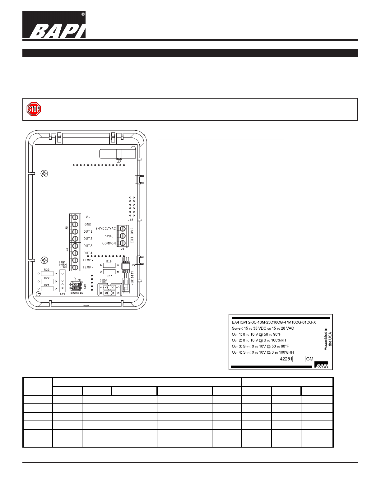
Termination
BAPI recommends using twisted pair of at least 22 AWG. Larger gauge wire may be required for long runs. All wiring
must comply with the National Electric Code (NEC) and local codes. Do NOT run this device’s wiring in the same conduit
as AC power wiring of NEC class 1, NEC class 2, NEC class 3 or with wiring used to supply highly inductive loads such
as motors, contactors and relays. BAPI’s tests show that uctuating and inaccurate signal levels are possible when AC
power wiring is present in the same conduit as the signal lines.
BAPI recommends wiring the product with power disconnected. Proper supply voltage, polarity, and wiring
connections are important to a successful installation. Not observing these recommendations may damage the
product and will void the warranty.
Terminal Notes: (Related to Table 1)
V+: Power. See Power Supply specications.
GND: Ground/Common for V+, OUT1, OUT2, OUT3, OUT4, and
TEMP- terminals when congured as Common Ground (default)
OUT1: Temperature, Temperature Setpoint, or Humidity Setpoint with
voltage or 4 to 20mA output.
OUT2: Humidity, Temperature Setpoint, or Humidity Setpoint with
voltage or 4 to 20mA output.
OUT3/OUT4: Temperature Setpoint or Humidity Setpoint with voltage
or resistive output. Resistive output can be wired as Differential
Ground. Optional override available.
TEMP+/-: Resistive temperature sensor. Optional override available.
Used as input for external sensor option (-ES). External sensor must
be a 10K-2 thermistor purchased separately (max wire length of 25ft).
A humidity output or resistive temperature sensor are not allowed in
this conguration.
EXT OVR: Wiring of the J6 External Override (EXT OVR) terminals is
not covered in this section. It is described in the “Override Display Icon
Activation” section on page 4.
See product label for conguration and termination information.
Fig. 3: BAPI-Stat “Quantum Prime”
Circuit Board
Table 1: Termination Table
Terminal
Name
Temp Humidity Temp Setpoint Humidity Setpoint Override Voltage Current Resistive
Output Variable Output Type
Fig. 4: Example
Product Label
OUT1 X X X X X
OUT2 X X X X X
OUT3 X X X X
TEMP- X X X
Specications subject to change without notice.
X (<50KΩ)
2 of 6
Page 3

BAPI-Stat “Quantum Prime” Temp & Humidity Sensor
Front Panel & Control Descriptions
Installation & Operating Instructions
rev. 03/23/2041148_ins_quantum_prime_hum
Minor Display
Override Icon
Major Display
Setpoint Buttons
Cycle Button
Override
Button
Fig. 5: BAPI-Stat “Quantum Prime” with
Temperature and Humidity Setpoint and Override.
All BAPI-Stat “Quantum Prime” sensors come with a display. Depending on the options selected, the sensor will have
one of three button congurations:
• No buttons;
• Setpoint & Override buttons (3 buttons);
• Setpoint, Cycle and Override (4 buttons) as shown in Figure 5.
Setpoint Buttons:
These buttons are used to change the setpoint. If your sensor has been ordered with setpoint adjustment for
both temperature and humidity, then the setpoint value that changes is the one that is showing in the major
display when the setpoint button is pressed. The major display digits will ash to indicate that the setpoint is
being changed.
Cycle Button:
This button is used to switch the temperature and humidity values between the major and minor display.
Override Button:
This button sends a signal to the controller to place the sensor location into an occupied status. The override
icon will appear in the display according to the wiring options described in the next section “Override Display
Icon Activation.”
Temperature Display:
Temperature can be displayed in Fahrenheit or Celsius. It is eld adjustable via the “F/C” switch on DIP Switch SW5 as
described in the “Optional Technician Adjustments” section on page 5.
Specications subject to change without notice.
3 of 6
Page 4

BAPI-Stat “Quantum Prime” Temp & Humidity Sensor
1000Ω RTD 1.02KΩ (41.20°F) 1.15KΩ (101.5°F)
3000Ω Thermistor 7.87KΩ (39.8°F) 1.5KΩ (106.8°F)
10K-2 Thermistor 30.1KΩ (34.9°F) 4.75Ω (109.1°F)
10K-3 Thermistor 26.7KΩ (35.9°F) 5.11KΩ (108.4°F)
10K-3(11K) Thermistor 7.32KΩ (43.7°F) 3.65Ω (105.2°F)
Installation & Operating Instructions
rev. 03/23/2041148_ins_quantum_prime_hum
Override Display Icon Activation
When the override button is pushed, a resistance of less than 100 ohms appears for a few seconds across the OUT3,
OUT4 or TEMP+/TEMP- terminals
override icon on the LCD will be lit for 10 seconds and then go blank.
If you would like the override icon to continue to display the “Occupied” or “Unoccupied” status of the room, then a
conrmation signal of 5 VDC across the 5VDC and COMMON terminals of J6, or 24 VDC/VAC across the 24VDC/VAC
and COMMON terminals of J6 is required. When the conrmation signal is received, both the outline and center of the
override icon will be lled in or solid, indicating that the room is in an occupied state (Fig 6).
When the conrmation signal is removed, the center portion of the override icon will go out
but the outline will remain lit, indicating that the room is in an unoccupied state. See the
Wiring Examples below (Figs 7 & 8) for more info on adding the conrmation signal.
If power to the sensor is removed, the override icon will be blank until the rst conrmation
signal is received as described above.
Note: The input signals on the terminals of J6 are optically isolated from the rest of the
device’s circuitry.
(depending on how the unit is ordered). Simultaneously, the outline and center of the
“Occupied”
Solid Icon
“Unoccupied”
Outline Icon
Fig. 6: Override Icon
Quantum Pri me
J6 Terminals
Controller
Digital
Output
5VDC Customer
Power Supply
Fig. 7: 5VDC Wiring Example
Controller Output OPEN
Optional Communication Jack Wiring
Optional Communication Jack Termination Wiring
Fig. 9: C11 Jack
Fig. 10: C35 Jack
=
Table: 3 C11/22 Wiring
Comm Jack Pin Wire Color
1 Not Connected
2 Black
3 Red
4 Yellow
5 White or Green
6 Not Connected
Table: 4 C35 Female Jack Wiring
Comm Jack Pin Wire Color
Ground Black
Tip White
Ring Red
Note: Male Jack shown for clarity
Quantum Pri me
J6 Terminals
Fig. 8: 24VDC/VAC Wiring Example
Controller Output CLOSED (Override) =
C11
C35
Fig. 11:
View of
BAPI-Stat
“Quantum
Prime”
Wallplate
Controller
Digital
Output
24VDC/VAC
Customer
Power Supply
Optional Test & Balance Switch (SW1)
- For Passive Sensor Output Only (Output at TEMP+ and TEMP- Terminals)
Optional Test and Balance Switch (SW1)
(Output at TEMP+ and TEMP- Terminals)
High: Will set the sensor value high
Norm: Thermistor/RTD will operate normally
Low: Will set the sensor value low
Specications subject to change without notice.
Sensor Type
Low Temp (40° F)
Resistance Value
High Temp (105°F)
Resistance Value
4 of 6
Page 5

BAPI-Stat “Quantum Prime” Temp & Humidity Sensor
3 Setpoint Not Displayed: Setpoint can be changed, but will not display
Item Display Action
0 Display in whole digits
1 Display in 0.5° increments, °F and °C
P7
P11
Humidity Setpoint Display High
P12
Humidity Setpoint Value
P13
Humidity Output Low
P16
Humidity Output High
P17
±5% in 0.1% increments (Humidity offset adjusts the display and output.)
Installation & Operating Instructions
Optional Technician Adjustments
The unit is shipped ready to install per the order. The following Setup or Program Menu Changes are
available if the installer decides to change the factory settings. Note: the programming pages require
setpoint and override buttons. The parameter adjustments are not available for units without buttons.
ENTERING PROGRAM MODE TO ADJUST PARAMETERS (see Figs 12-14 for adjustment tools)
1. Power unit and set DIP Switch SW5 #2 (PROGRAM) to ON (right). The LCD will show a page
number (P1-P19). P1-P19 will ash to indicate that display parameter can be adjusted.
2. The Setpoint Up/Down buttons on the front of the unit are used to scroll up and down through
pages and adjusting the page parameters.
3. The Override button acts as “Enter” to switch between page number and adjusting the page
parameter.
4. After a page parameter has been adjusted, push the Override button to conrm the change.
5. To exit Program Mode, Set DIP Switch SW5 #2 (PROGRAM) to OFF (left).
Note: DIP Switch SW5 #1 (°F/C) can be used to switch the display between °F and °C.
Programming Pages
Parameter Page
Temperature Offset P1
Humidity Offset P2
Setpoint Lockout
(If resistive temp output, offset only adjusts display. If voltage or current temp output, offset adjusts display & output.)
Item Display Action
0 Setpoint Enabled
1 Setpoint Disabled: Display shows setpoint when activated, but can't be changed
P3
Setpoint Display: Shows setpoint in major display and shows opposite local temperature or humidity in minor
2
Adjustment
±5° in 0.1° increments
display
rev. 03/23/2041148_ins_quantum_prime_hum
Fig. 12: DIP
Switch SW5
Fig. 13:
Setpoint
Up/Down
Buttons
Fig. 14:
Override
Button
Humidity Display P5
Temperature Setpoint Display Low
Temperature Setpoint Display High
OUT3 Setpoint Output Low
OUT3 Setpoint Output High
Temperature Setpoint Value
Humidity Setpoint Display Low
Temperature Output Low
Temperature Output High
OUT4 Setpoint Output Low
OUT4 Setpoint Output High
P4Temperature Display
2 Display in 0.1° increments, °F and °C
Item Display Action
0 Display in whole digits
1 Display in 0.5% increments
2 Display in 0.1% increments
P6
P8
P9
P10
P14
P15
P18
P19
Adjust the Low Temperature of the output range (Note: Minimum -40°F/-40°C. Active temperature output only)
Adjust the High Temperature of the output range (Note: Maximum 185°F/85°C. Active temperature output only)
Adjust the Low Temperature of the setpoint range (Note: Minimum -40°F/-40°C)
Adjust the High Temperature of the setpoint range (Note: Maximum 185°F/85°C)
Low Setpoint Output Range (Note: Read Only. Displayed in 10 ohm resolution. Voltage
outputs will be shown in ohms)
High Setpoint Output Range (Note: Read Only. Displayed in 10 ohm resolution. Voltage
outputs will be shown in ohms)
Shows current temperature setpoint value (Note: Ready Only)
Adjust the Low Humidity of the setpoint range (Note: Minimum 0%RH)
Adjust the High Humidity of the setpoint range (Note: Maximum 100%RH)
Shows current humidity setpoint value (Note: Ready Only)
Adjust the Low Humidity of the output range (Note: Minimum 0%RH)
Adjust the High Humidity of the output range (Note: Maximum 100%RH)
Low Setpoint Output Range (Note: Read Only. Displayed in 10 ohm resolution or 1
ohm resolution depending on setpoint output. Voltage outputs will be shown in ohms)
High Setpoint Output Range (Note: Read Only. Displayed in 10 ohm resolution or 1
ohm resolution depending on setpoint output. Voltage outputs will be shown in ohms)
Specications subject to change without notice.
5 of 6
Page 6

Diagnostics
POSSIBLE PROBLEMS
General diagnostics
BAPI-Stat “Quantum Prime” Temp & Humidity Sensor
Installation & Operating Instructions
rev. 03/23/2041148_ins_quantum_prime_hum
POSSIBLE SOLUTIONS:
- Verify that the input is set up correctly in the controller’s and building automation software.
- Check for proper power at the sensor as described in the specications below.
- Check wiring for proper termination and for corrosion at either the controller or the sensor.
Clean off the corrosion, re-strip the interconnecting wire and reapply the connection. In
extreme cases, replace the controller, interconnecting wire and/or sensor.
- Check for a wiring problem between the unit and the controller. Label the terminals at
the sensor end and the controller end. Disconnect the interconnecting wires at both
ends and measure the resistance from wire-to-wire with a multimeter. The meter should
read greater than 10 Meg-ohms, open or OL depending on the meter you have. Short
the interconnecting wires together at one end. Go to the other end and measure the
resistance from wire-to-wire with a multimeter. The meter should read less than 10 ohms
(22 gauge or larger, 250 feet or less). If either test fails, replace the wire.
Passive temperature
sensor reading
is incorrect at the
controller
- Measure the physical temperature at the sensor’s location using an accurate temperature
standard. Disconnect the temperature sensor wires at the TEMP+ and TEMP- terminals
and measure the temperature sensor’s resistance across the terminals with an ohmmeter.
Compare the temperature sensor’s resistance to the appropriate temperature sensor table
on the BAPI website. If the measured resistance is different from the temperature table
by more than 5% call BAPI technical support. Find BAPI’s website at www.bapihvac.com;
click on “Resource Library” and “Sensor Specs” then click on the type of sensor you have.
Don’t forget to reconnect the wires.
- If the unit has a Test and Balance switch, make sure it is in the correct position.
Specications
Power Supply:
10 to 40 VDC (15 to 24 VDC Recommended) for 4 to 20 mA or 0 to 5 VDC Outputs
15 to 40 VDC (15 to 24 VDC Recommended) for 0 to 10 VDC Outputs
12 to 28 VAC (Requires a separate pair of shielded wires) for 0 to 5 VDC Outputs
Power Consumption:
60 mA maximum DC: 4 to 20 mA Output (<30mA typical)
36 mA maximum DC: 0 to 5 VDC or 0 to 10 VDC Outputs (6mA typical)
0.9 VA maximum AC: 0 to 5 VDC or 0 to 10 VDC Outputs (0.2VA typical)
Outputs: 4 active outputs plus 1 passive temperature sensor
Volts .......................0 to 5 VDC or 0 to 10VDC, Impedance >10KΩ (OUT1, OUT2, OUT3, OUT4)
Current ...................4 to 20 mA, Impedance <500Ω @ 24 VDC (OUT1, OUT2)
Resistance .............
Relay Contact ........ N.O., 500 mA @ 24 VDC max
Temp. Sensor .........Passive RTD or Thermistor (TEMP+/TEMP-)
Inputs:
External Override ...5 VDC or 24 VDC/VAC
External Sensor ..... 10K-2 Themistor purchased separately. Wired 25’ max from sensor
Sensing Elements for Active Outputs and Display:
Temperature ...........10K-2 Thermistor
Humidity .................Capacitive Polymer, ±2%RH
Sensing Element for Resistive Temp Output: Thermistor or RTD
Mounting: 2” by 4” J-box or drywall mount - screws provided
Environmental Ambient:
Temperature ...........32 to 122ºF (0 to 50ºC)
Humidity .................0 to 95%, non-condensing
Storage .................. 32 to 185°F (0 to 85°C)
Setpoint, 5 VDC @ 5 mA max (OUT3, OUT4) - Factory selected per application
Wiring: 2 to 6 pair of 16 to 22 AWG
Enclosure Material: ABS Plastic, UL 94, V-0
Agency: RoHS
Specications subject to change without notice.
6 of 6
 Loading...