

Page 1
BAPI-Stat 4 “X-Combo”, Room %RH and Temp. Sensor
BA/BS4XC
Installation & Operating Instructions
rev. 10/28/1627939_ins_BS4XC
Overview and Identication
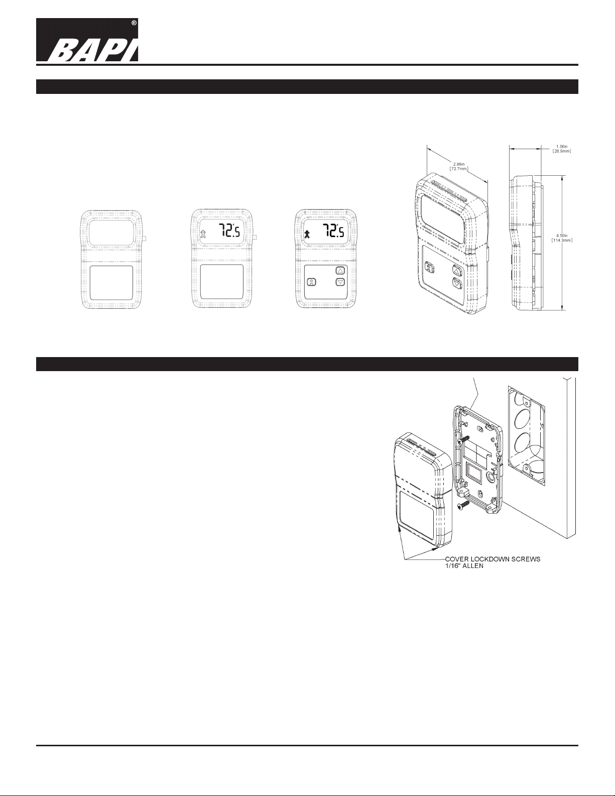
The BAPI-Stat 4 “X-Combo” (BA/BS4XC) Room Unit features 4 output channels and optional local indication of
temperature and humidity. Additional options include Temperature Setpoint, Humidity Setpoint and Local Override.
The optional LCD shows room temperature in °C or °F and room humidity in %RH. In addition, the unit has adjustable
offsets for both temperature and humidity and is capable of having the range for
the temp., humidity and setpoints changed in the eld.
The unit has 4 output channels. Channel 1 and 2 can be ordered as voltage
or current, channel 3 as voltage or resistance and channel 4 as a passive
temperature sensor or isolated override contact.
Fig. 2: Unit with
Override but No
Display or Setpoint
Fig. 3: Unit with
Override and Display
but No Setpoint
Fig. 4: Unit with
Override, Display
and Setpoint
Fig. 1: BAPI-Stat 4
X-Combo Dimensions
Mounting
JUNCTION BOX
1. Pull the wire through the wall and out the junction box, leaving about six
inches free. Pull the wire through the hole in the base plate.
2. Secure the base to the box using the #6-32 x 5/8 inch mounting screws
provided.
3. Terminate the unit according to the guidelines in the Termination section.
4. Attach Cover by latching it to the top of the base, rotating the cover down
and snapping it into place.
5. Secure the cover by backing out the lock-down screws using a 1/16” Allen
wrench until they are ush with the bottom of the cover.
DRYWALL MOUNTING
1. Place the base plate against the wall where you want to mount the sensor.
Mark the two mounting holes and the area where the wires will come
through the wall.
2. Drill two 3/16” holes in the center of each marked mounting hole. Insert a
drywall anchor into each hole.
3. Drill one 1/2” hole in the middle of the marked wiring area. Pull the wire
through the wall and out of the 1/2” hole, leaving about six inches free.
4. Pull the wire through the hole in the base plate.
5. Secure the base to the drywall anchors using the #6 x 1 inch mounting screws provided.
6. Terminate the unit according to the guidelines in the Termination section.
7. Attach Cover by latching it to the top of the base, rotating the cover down and snapping it into place. Secure the cover by
backing out the lock-down screws using a 1/16” Allen wrench until they are ush with the bottom of the cover.
Fig. 5: Mounting hardware is provided for
both junction box and drywall installation
(junction box installation shown).
NOTE: In a wall-mount application, the mixing of room air and air from within the wall cavity can lead to erroneous readings,
condensation, and premature failure of the sensor. To prevent this condition, plug the conduit hole with insulation in the
junction box.
Specications subject to change without notice.
1 of 8
Page 2
BAPI-Stat 4 “X-Combo”, Room %RH and Temp. Sensor
BA/BS4XC
Installation & Operating Instructions
rev. 10/28/1627939_ins_BS4XC
Termination
BAPI recommends using twisted pair of at least 22AWG and sealant lled connectors for all wire connections. Larger
gauge wire may be required for long runs. All wiring must comply with the National Electric Code (NEC) and local
codes. Do NOT run this device’s wiring in the same conduit as AC power wiring. BAPI’s tests show that uctuating and
inaccurate signal levels are possible when AC power wiring is present in the same conduit as the signal lines. If you are
experiencing any of these difculties, please contact your BAPI representative.
BAPI recommends wiring the product with power disconnected. Proper supply voltage, polarity, and wiring
connections are important to a successful installation. Not observing these recommendations may damage the
product and will void the warranty.
Terminal Description
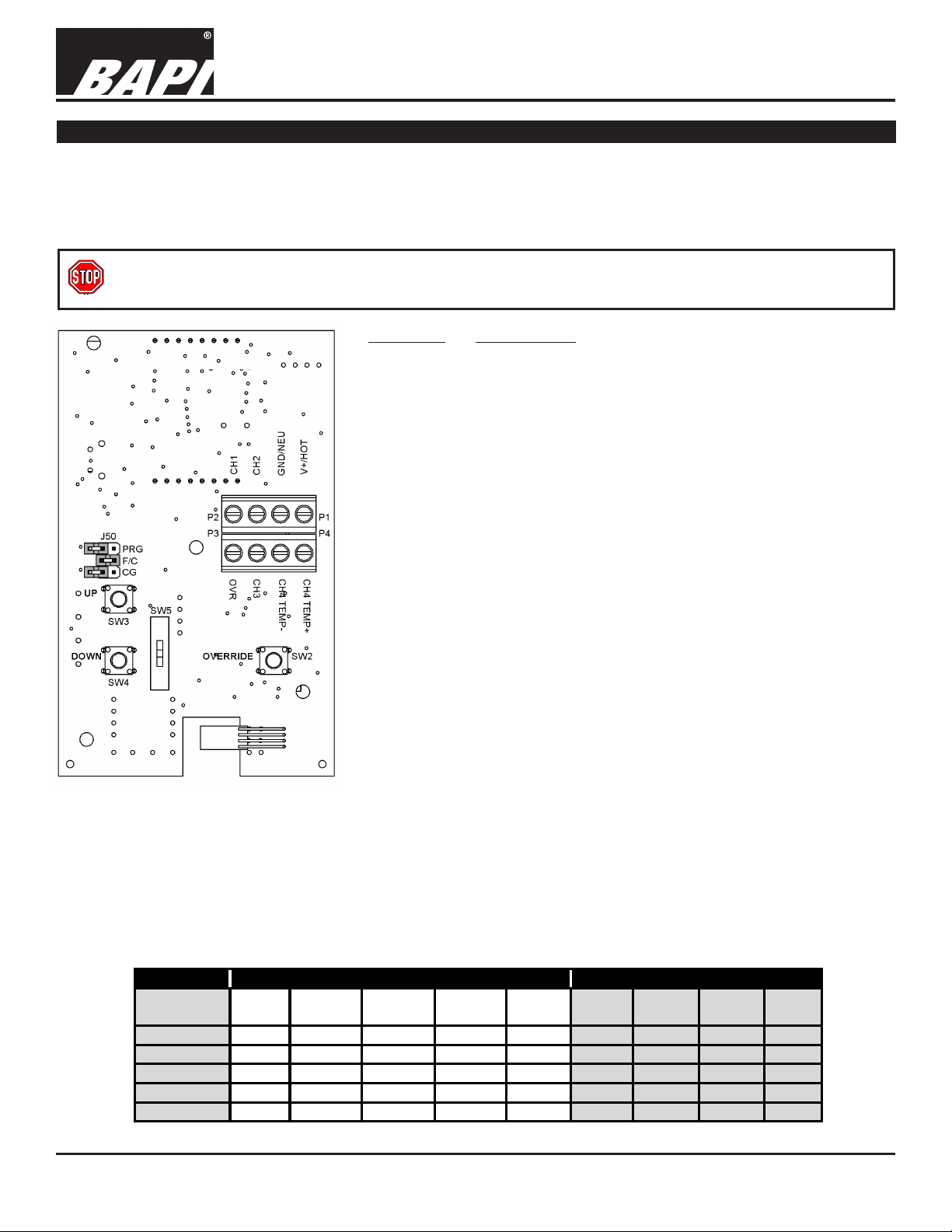
GND/NEU
........Power Supply Common Ground (Ground to the Controller)
Fig. 6: X-Combo Circuit Board
Circuit Board Note: If a display unit is
ordered with Setpoint Adjustment, then
Switches 3 & 4 will NOT be present
on the BACK of the circuit board. If a
display unit is ordered with Override,
then Switch 2 will NOT be present on
the back of the circuit board.
V+/HOT
CH1
...........Power Supply Hot (See specications for voltage details)
.................Ch. 1 Signal, Voltage or 4 to 20mA*, referenced to
Common Ground
CH2
.................Ch. 2 Signal, Voltage or 4 to 20mA*, referenced to
Common Ground
CH3
.................Ch. 3 Signal, Voltage or Resistance, referenced to
Common Ground
CH4 TEMP+
....Channel 4 + Signal, Passive Temp Sensor and/or
Override Contact, referenced to “CH4 TEMP -”
(**See “Grounding Note” below)
CH4 TEMP- .....Channel 4 - Signal, Passive Temp Sensor and/or Override
Contact (**See “Grounding Note” below).
OVR
.................Override input to turn on the Occupied BAPI-Man on the
Display, referenced to Common Ground
*4-20mA Note:
This current output is NOT a loop powered output. It sources the power
for the loop per the specication.
**Grounding Note:
Common Ground (-CG) or Differential Ground (-DF) are selected
per order but can be changed in the eld (see Optional Technician
Adjustments section). In -DF Mode, the “CH4 TEMP–” and “CH4 TEMP+”
terminals are isolated from the rest of the sensor. In -CG Mode, the “CH4
TEMP–” terminal is internally connected to the power ground terminal
GND/NEU.
Channel Output Variable Output Type
Terminal Temp Humidity Temp Humidity Override Voltage Current Resistive 592/334
Name Setpoint Setpoint Sourcing
CH1 X X X X X X
CH2 X X X X X X
CH3 X X X X <50KΩ
CH4 TEMP + X X Sensor V +
CH4 TEMP - X X Sensor V -
Specications subject to change without notice.
2 of 8
Page 3
BAPI-Stat 4 “X-Combo”, Room %RH and Temp. Sensor
Resistance Value
Resistance Value
10K-2 Thermistor 30.1KΩ (34.9°F) 4.75Ω (109.1°F)
10K-3 Thermistor 26.7KΩ (35.9°F) 5.11KΩ (108.4°F)
Optional Communication Jack Wiring
Fig. 7: Back
Plate of the
BAPI-Stat 4
BA/BS4XC
Installation & Operating Instructions
rev. 10/28/1627939_ins_BS4XC
Fig. 8: C35L
Comm. Jack
(male jack
shown for clarity)
C35L
C11L/
C22L
Comm Jack Pin Wire Color
Fig. 9: C11L/C22L
Comm. Jack
C11L/C22L Wiring
1 Not Connected
2 Black
3 Red
4 Yellow
5 Green
6 Not Connected
Optional Test and Balance Switch (SW5)
The test and balance switch is used by the balancer to equalize the ow of air or water per the design prints. This
switch can also be used by the commissioning technician to verify sensor termination in a point to point checkout of the
control system. The “Run” position allows the real sensor to be monitored. The “High” position forces the output to a
very hot reading and the “Low” position forces the output to a very cold output. The table below shows the most common sensor output readings.
High Temp (105°F)
Low: Sets the sensor value low
Sensor Type
Low Temp (40° F)
1000Ω RTD 1.02KΩ (41.20°F) 1.15KΩ (101.5°F)
Run: Sensor operates normally
High: Set the sensor value high
3000Ω Thermistor 7.87KΩ (39.8°F) 1.5KΩ (106.8°F)
10K-3(11K) Thermistor 7.32KΩ (43.7°F) 3.65Ω (105.2°F)
Display and Front Panel Button Operation
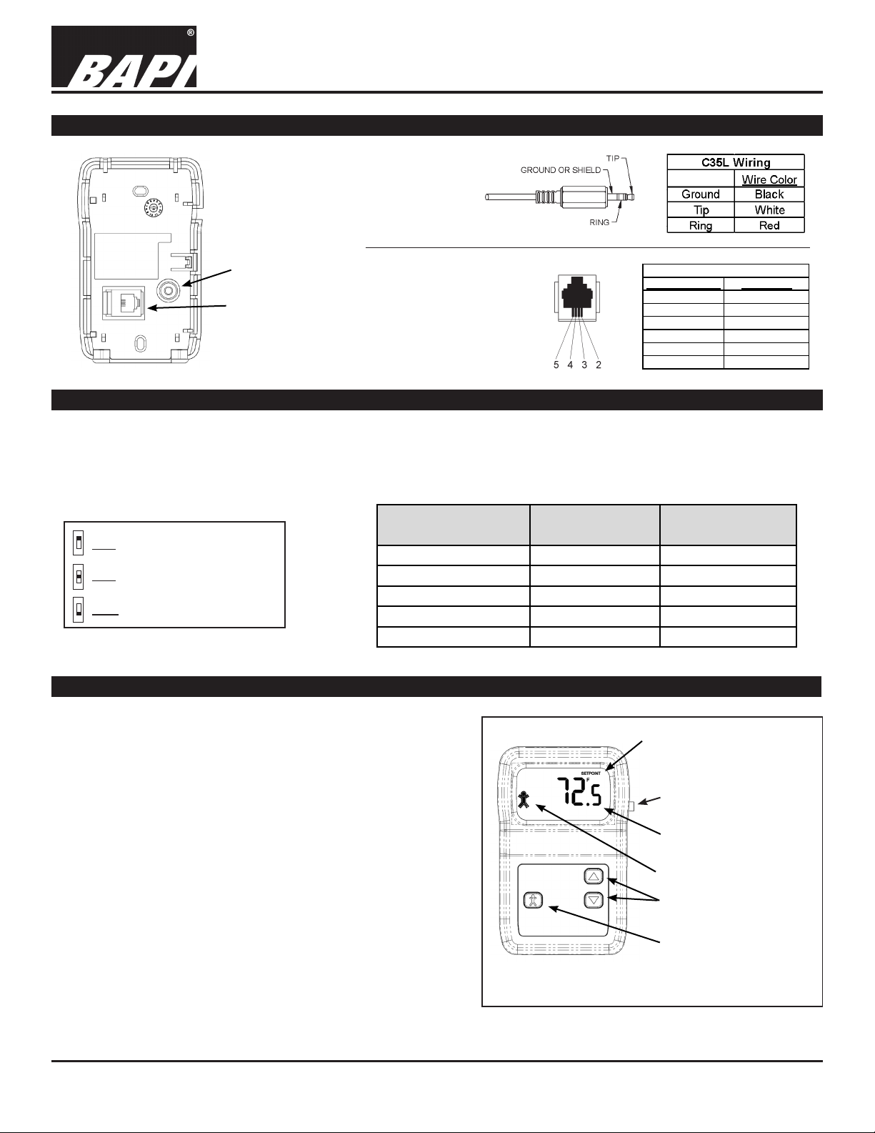
The “X-Combo” is available with optional LCD, override and
setpoint buttons. See Fig. 10 for a fully featured sensor.
NUMERICAL DISPLAY:
The default numerical display shows current temperature, and
toggles to humidity display at an adjustable rate of 1 to 20
seconds. When the up/down buttons are pushed, the display
will show and adjust the current setpoint and hold that display
for 3 seconds. The unit can also be programmed to “setpoint
only” display or setpoint lockout. See pages 4-5.
BAPI-MAN INDICATOR (FIG. 11):
The BAPI-Man on the display indicates whether the room is in
the “Occupied” (solid) or “Un-occupied” (hollow) status.
Note: The unit must receive a conrmation (ground) signal on
the “OVR” terminal for the BAPI-Man to remain visible on the
screen. Pressing the Override button will light the BAPI-Man
indicator; however, if no conrmation signal is received, then
the BAPI-Man will go blank (disappear) after 5 seconds.
Continued on next page....
Specications subject to change without notice.
“Setpoint” word Indicates
that the Setpoint is being
displayed.
Override Pushbutton for
Units without Setpoint
Temperature Display in
.5 Degree Increments
“BAPI-Man” Indicator
Setpoint Up/Down
Buttons
Override Pushbutton
Fig. 10: X-Combo with LCD, Setpoint and Override
3 of 8
Page 4

BAPI-Stat 4 “X-Combo”, Room %RH and Temp. Sensor
BA/BS4XC
Installation & Operating Instructions
rev. 10/28/1627939_ins_BS4XC
Display and Front Panel Button Operation continued...
Upon receiving a rst conrmation (ground) signal on the “OVR” terminal, the
BAPI-Man will show occupied (solid). The BAPI-Man will then show un-occupied
(hollow) whenever the conrmation signal is removed and occupied when the signal
is returned. The only way to blank the BAPI-Man from the display at this point is to
cycle power.
OVERRIDE BUTTON:
When the override button is pressed, the BAPI-Man will be displayed (solid) for 3-5
Solid equals
“Occupied”
Fig. 11: BAPI-Man Indicator
seconds and the override output will shunt or short for 5 seconds depending on the
override option selected. Momentary closure of the selected channel goes to its
minimum value for 5 seconds (Voltage goes to 0, 1, or 2 volts, current goes to 4mA, resistance goes to ~10Ω or the
channel 4 value goes to <1Ω on terminals “CH4 TEMP+” to “CH4 TEMP-”). If an override conrmation (ground) signal
is received on the “OVR” terminal, then the BAPI-Man will stay lled in, indicating an occupied status. If no conrmation
signal is received, then the BAPI-Man will revert to a hollow man display, indicating an un-occupied status. (See “BAPIMan Indicator” above for more information.)
TEMPERATURE SETPOINT:
Press the Setpoint Up/Down buttons once to enter the Setpoint Adjustment Mode. View the display to see whether
you are in Temperature or %RH Setpoint mode. If needed, press the Override Button once to toggle to Temperature
Setpoint mode. The current temperature setpoint will display for 5 seconds. When the Setpoint Up/Down buttons are
pressed in this mode, the temperature setpoint will change in one degree increments. It will only change within the
setpoint range that was ordered. After 5 seconds of no buttons being pushed, the sensor will go into the standard
display or toggle mode.
%RH SETPOINT:
Press the Setpoint Up/Down buttons once to enter the Setpoint Adjustment Mode. View the display to see whether you
are in Temperature or %RH Setpoint mode. If needed, press the Override Button once to toggle to the %RH Setpoint
Adjustment Mode. The current %RH Setpoint will display for 5 seconds. Pressing the UP/Down buttons will change the
selected setpoint by 1% increments. After 5 seconds of no buttons being pushed, the sensor will go into the standard
display or toggle mode.
Hollow equals
“Un-occupied”
Optional Technician Adjustments (The sensor set-up is factory set per your order. Set-up adjustments are not required)
The unit is shipped ready to install per the order and does not require any special setup or programming. The following
Set-up or Program Menu Changes are available if the installer decides to change the factory settings. Program Menu
changes require a display on the sensor. Non-display sensors must be factory congured.
Note: The Setpoint Up/Down Buttons and Override Button are used to make Menu changes. If the unit is ordered
without Setpoint Adjustment or Override, then buttons will be located on the back of the PCB inside the sensor. See
Figure 6 on page 2. These buttons will not be present on the PCB if the unit has been ordered with Setpoint and
Override.
SET-UP JUMPER (J50) CONFIGURATION: (FACTORY SET PER ORDER)
Label Description Setting
PRG Program Mode Program Mode = Jumper installed for Program Mode (See Program Menu below)
or Run Mode Run Mode = Jumper removed for Run Mode (Place jumper on one pin only)
F/C ˚C Indication ˚C = Jumper installed for °C Indication
or ˚F Indication ˚F = Jumper removed for °F Indication (Place jumper on one pin only)
CG Common Ground Common Ground = Jumper installed for Common Ground
or Differential (“CH4 TEMP-” terminal connected to ground)
Differential Ground = Jumper removed for Differential Ground
(“CH4 TEMP-” terminal isolated from ground)
Continued on next page....
Specications subject to change without notice.
Fig. 12:
J50 Jumper
4 of 8
Page 5

BAPI-Stat 4 “X-Combo”, Room %RH and Temp. Sensor
BA/BS4XC
Installation & Operating Instructions
rev. 10/28/1627939_ins_BS4XC
Optional Technician Adjustments continued....
PROGRAM MODE MENU PAGES: (DISPLAY REQUIRED)
Note: The J50 jumper “ ˚F/˚C “ selection determines what engineering unit is used for the following program mode.
Make sure to selected the desired ˚F or ˚C before adjusting the program values below.
ENTERING PROGRAM MODE AND MAKING CHANGES:
1. Install the J50 “PRG” jumper onto both pins to enter Program Mode.
2. Press the Up/Down Buttons to advance to the desired program parameter from P1 through P17.
(Parameters described below).
3. Press the Override Button to select the specic program parameter to change.
4. Change the parameter value as described in the Mode Menus section below.
5. Press the Override Button again to set the selected parameter.
6. Press the Up/Down Buttons to proceed to the next parameter (as in Step 3 above).
7. When done making changes, remove the J50 “PRG” jumper (and place over one pin) to end the programming
mode and store all the values. The sensor is now in the run mode.
MODE MENUS
P1 - Display Selection (Move the Setpoint Up/Down Arrows to change the display mode. Factory default setting is
“03”)
00 = No display (Blank)
01 = Temp display only
02 = %RH display only
03 = Temp and %RH display, toggling
04 = Temp Setpoint display only
05 = Temp and Temp Setpoint display, toggling
06 = %RH and Temp Setpoint display, toggling
07 = Temp, %RH and Temp Setpoint display, toggling
08 = %RH Setpoint only
09 = Temp and %RH Setpoint display, toggling
10 = %RH and %RH Setpoint display, toggling
11 = Temp, %RH and %RH Setpoint display, toggling
12 = Temp Setpoint and %RH Setpoint display, toggling
13 = Temp, Temp Setpoint and %RH Setpoint display, toggling
14 = %RH, Temp Setpoint and %RH Setpoint display, toggling
15 = Temp, %RH, Temp Setpoint & %RH Setpoint display, toggling
P2 - Display Toggle Rate (Factory default is 5 seconds)
Move the Up/Down arrows in 1 second increments up to 20 seconds between variables as selected in P1.
P3 - Temperature Span Low Limit (Factory set per order)
Move the UP/Down arrows in 1˚ increments between -40 to 140 span. (˚F or ˚C must be selected rst on
Jumper J50.)
P4 - Temperature Span High Limit (Factory set per order)
Move the UP/Down arrows in 1˚ increments between -40 to 140 span. (˚F or ˚C must be selected rst on
Jumper J50.)
Continued on next page....
Specications subject to change without notice.
5 of 8
Page 6

BAPI-Stat 4 “X-Combo”, Room %RH and Temp. Sensor
BA/BS4XC
Installation & Operating Instructions
rev. 10/28/1627939_ins_BS4XC
Optional Technician Adjustments continued....
MODE MENUS Continued....
P5 - %RH Span Low Limit: (Factory set per order)
Move the UP/Down arrows in 1% increments between 0% to 100% span.
P6 - %RH Span High Limit: (Factory set per order)
Move the UP/Down arrows in 1% increments between 0% to 100% span.
P7 - Fixed Temperature Setpoint (Must be within the Temperature spans set in menu page P3 and P4.)
This function is used for Temperature Setpoint Lockout Only. Move the UP/Down arrows in 1˚ increments
between -40 to 140 span. (˚F or ˚C must be selected rst on Jumper J50.)
P8 - Temperature Setpoint Span Low Limit (Must be within the Temp spans set in menu page P3 and P4.)
Move the UP/Down arrows in 1˚ increments between -40 to 140 span. (˚F or ˚C must be selected rst on
Jumper J50.)
P9 - Temperature Setpoint Span High Limit (Must be within the Temp spans set in menu page P3 and P4.)
Move the UP/Down arrows in 1˚ increments between -40 to 140 span. (˚F or ˚C must be selected rst on
Jumper J50.)
P10 - %RH Setpoint (Must be within the RH spans set in menu page P5 and P6.)
This function is used for %RH Setpoint Lockout Only. Move the UP/Down arrows in 1% increments between 0%
to 100% span.
P11 - %RH Setpoint Span Low Limit (Must be within the RH spans set in menu page P5 and P6.)
Move the UP/Down arrows in 1% increments between 0% to 100% span.
P12 - %RH Setpoint Span High Limit (Must be within the RH spans set in menu page P5 and P6.)
Move the UP/Down arrows in 1% increments between 0% to 100% span.
P13 - Temperature Offset
Move the UP/Down arrows in 0.1˚ increments between -5 to +5 ˚F or °C. This affects both the display and signal
output values.
P14 - %RH Offset
Move the UP/Down arrows in 0.1% increments between -5% to +5%. This affects both the display and the
signal output values.
P15 - Test & Balance Channel 1:
This only applies to the active Ch. 1 output. The passive sensor must use the (-TB) option and a board
mounted 3 position switch.
Move the UP/Down arrows to “+1” to output a high temp output. Move the UP/Down arrows to “0” to output
the normal temp value on the output. Move the UP/Down arrows to “-1” to output a low temp output. On exit
from programming mode, the active Test & Balance will no longer be active, so the output changes to the live
variable.
P16 - Setpoint Lockout (Move the UP/Down arrows to change the lockout mode desired.)
00 = No Setpoint Lockout (Default)
01 = Temperature Setpoint Lockout Only. (See P7 for lockout value)
02 = Temperature Setpoint Lockout and %RH Setpoint Lockout. (See P7 and P10 for lockout value)
03 = %RH Setpoint Lockout Only. (See P10 for lockout value)
P17 - Temperature Display Resolution (Move the UP/Down arrows to change the resolution to the desired value.)
01 = .1 Degree Temperature Resolution
02 = .5 Degree Temperature Resolution (Default)
03 = 1 Degree Temperature Resolution
Specications subject to change without notice.
6 of 8
Page 7

BAPI-Stat 4 “X-Combo”, Room %RH and Temp. Sensor
Diagnostics - Temperature Output
Problems:
Temperature
Reading is
Incorrect
Possible Solutions
- Check for proper wire terminations and determine that the temperature input is set up correctly in the
controller and in the building automation software.
- Check the wiring between the sensor and controller. Label the terminals at the sensor end and the
controller end. Disconnect the interconnecting wires from the controller and the sensor. With the
wires disconnected, measure the resistance from wire-to-wire with a multimeter. The meter should
read greater than 10 Meg-ohms, open or OL depending on the meter. Short the interconnecting
wires together at one end. Go to the other end and measure the resistance from wire-to-wire with a
multimeter. The meter should read less than 10 ohms (22 gauge or larger, 250 feet or less). If either
test fails, replace the wire.
- Check the sensor temperature output against a reference. Measure the temperature at the sensor’s
location using an accurate temperature standard. Disconnect the temperature channel wires and
measure the temperature signal with a multi-meter and compare to the reference temperature. For
resistive output units, use the “Sensor Specs” tables in the “Resource Library” section of the BAPI
website (www.bapihvac.com) for the reference. For voltage or current output units, use the equations
below for the reference. If the output and reference differ by more than 5%, call BAPI technical support.
- Make sure that the Test and Balance switch is in the correct position.
- Make sure that the temperature sensor element leads are not touching one another.
- Determine if the sensor is exposed to an external source different from the room environment (conduit
draft). Plug the conduit or ll the handy box as necessary. DO NOT use silicon caulk.
BA/BS4XC
Installation & Operating Instructions
rev. 10/28/1627939_ins_BS4XC
Setpoint
reading is
incorrect
- Make sure that the setpoint output is correct. Remove the
setpoint output wire (Channel 1, 2 or 3. See product label for
conguration.) and check
the output for the correct
resistance, current or
voltage output. Call BAPI
technical support if the
value doesn’t match the
label.
Diagnostics - Humidity Output
Problems:
Humidity
Reading is
Incorrect
Possible Solutions
- Check for proper wire terminations and determine that the humidity input is set up correctly in the
controller and in the building automation software.
- Check the wiring between the sensor and controller (as described above).
- Check the sensor humidity output against a reference. Measure
the humidity at the sensor’s location using an accurate standard.
Disconnect the humidity channel wires and measure the humidity
signal with a multi-meter and compare to the reference, using the
equations at right for the reference. If the output and reference differ
by more than 5%, call BAPI
technical support.
- Determine if the sensor
is exposed to an external
source different from the room
environment (conduit draft).
Plug the conduit or ll the
handy box as necessary. DO
NOT use silicon caulk.
4-20mA Temperature Equation
T = TLow + (A -4) x (TSpan)
16
T = Temperature at sensor
TLow = Low temperature of span
THigh = High temperature of span
TSpan = THigh - TLow
A = Signal reading in mA
4-20mA Humidity Equation
RH = RHLow + (A -4) x (RHSpan)
16
RH = %RH at sensor
RHLow = Low %RH of Span
RH
High = High %RH of Span
RH
Span = RHHigh - RHLow
A = Signal reading in mA
Voltage Temperature Equation
T = TLow + (V-VLow) x (TSpan)
VSpan
T = Temperature at sensor
TLow = Low temperature of span
THigh = High temperature of span
TSpan = THigh - TLow
VLow = Low transmitter voltage
usually=(0, 1 or 2v)
VHigh = High transmitter voltage
usually=(5 or 10v)
VSpan = VHigh - VLow
V = Signal reading in volts
Voltage Humidity Equation
RH = RHLow + (V-VLow) x (RHSpan)
VSpan
RH = %RH at sensor
RH
Low = Low %RH of Span
RH
High = High %RH of Span
RH
Span = RHHigh - RHLow
VLow = Low transmitter voltage
usually=(0, 1 or 2v)
VHigh = High transmitter voltage
usually=(5 or 10v)
VSpan = VHigh - VLow
V = Signal reading in volts
7 of 8
Page 8

BAPI-Stat 4 “X-Combo”, Room %RH and Temp. Sensor
BA/BS4XC
Installation & Operating Instructions
rev. 10/28/1627939_ins_BS4XC
Specications
Supply Voltage: ................ 16 to 30 VDC or 18 to 30 VAC
Supply Power: .................. VDC = 50mA
Temperature Sensor: ....... Semiconductor Band gap, ±0.5ºC
%RH Sensor:
Available Outputs: ........... 3 Congurable, 1 Passive Sensor
Channels 1 & 2 ................Voltage or Current
Channel 3......................... Voltage or Resistance
Channel 4......................... Passive Sensor, Dedicated override contact
Output Signals: ................ Direct or reverse acting available
Voltage ............................. VDC 0 to 5V, 1 to 5V, 0 to 10V, 2 to 10V, Impedance>10KΩ, (ref. to common ground)
Current (Sourcing) .......... 4 to 20mA, 500Ω @11.5 VDC (referenced to common ground)
Resistance (Setpoint) ...... Available on Ch. 3 Only
Passive Sensor (Ch. 4) .... Thermistor, RTD or Solid State,
-CG Units, “TEMP-” terminal is Common Ground,
-DF Units, “TEMP” terminals are isolated
Thermistor, ±0.36ºF (±0.2ºC),
High Accuracy Thermistor [XP], ±0.18ºF (±0.1ºC)
Platinum RTD, ±0.12%, [A] ±0.06%
Nickel RTD, 1000Ω @70ºF, JCI curve
Solid State, AD592 or LM334
Digital Input (DI): .............. Occupied dry DI input (lights BAPI-Man on display)
Program Controls: ........... Requires display. See “Program Mode” section
Offset ............................... Temperature or Humidity
Range Setup.................... Temperature, Humidity or Setpoint - Limits: -40 to 140°F or °C or 0 to 100%RH
Display Setup ..................Temp./%RH/Setpoint with adjustable toggle rate
Display Units.................... °F, °C, %RH, Setpoint, BAPI-Man
Field Conguration: ........ J50 Jumper Pins
Channel 4 Ground .......... CG = Jumper installed, “TEMP-” is Common Ground
DF = Jumper removed, terminals Isolated (DF Mode)
˚F/˚C Indication ................ ˚C = Jumper installed, ˚F = Jumper removed
Program Mode ................ ON = Jumper installed for Program Mode
PRG = Jumper removed for Run Mode
Optional Faceplate Controls:
Setpoint ...........................Up/Down Buttons (requires display)
Override (BAPI-Man) ....... Momentary occupied request button (5 sec), or setpoint mode change if in Setpoint Mode
Test & Balance ................. 3-position switch for passive sensor
Optional Override: ........... Shunt on any one of 4 Channels
Face Button ..................... Used on Setpoint units
Side Button ...................... Used on Non-Setpoint units
Optional Comm. Jack: ..... Located in base: -C11 = RJ11, 4 wires • -C35 = 3.5mm, 3 wire • -C22 = RJ22, 4 wires
Optional Colored Plate: .... -WMW = Warm White plate • -GRY = Gray plate
Test & Balance: ................ 3 Temp. Positions: High/Run/Low
Active type ...................... Program Mode, Ch. 1, (Prog. page P15)
Passive Sensor ............... Optional for Ch. 4 w/ 3-Way Internal Switch
Optional Display: ............. LCD-Temp, RH, Setpoint, Override
Display size ....................2.04”W x 1.33”H
Digits................................ ±999.9 Digits @0.6”H
Resolution........................ 0.5 displayed value, 0.1 for offset adjust
Units ................................˚F, ˚C, %, BAPI-Man, Setpoint
Value Displayed ............... Always shows the value regardless of the output range
Termination: ..................... 8 Terminals, 16 to 22 AWG
Mounting: ......................... Standard 2x4” J-Box or Drywall
Enclosure Material: .........ABS Plastic, UL94V-0
Ambient (Enclosure): ...... 32 to 122ºF (0 to 50ºC), 0 to 95% RH, Non-condensing
Agency: ............................RoHS
.................... 2% Accuracy from 20 to 80%, Capacitive
Specications subject to change without notice.
8 of 8
 Loading...