

Page 1
37498_BS4S_NoDisplay_LNX
Product Identication and Overview
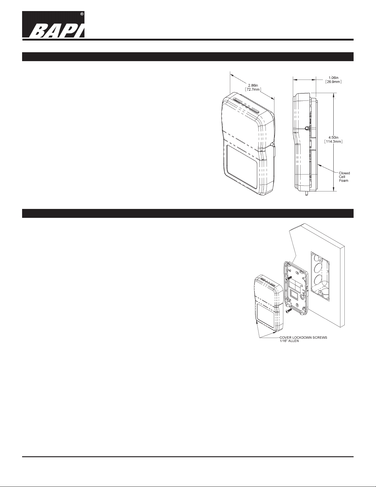
The BAPI-Stat 4 LNX unit features a modern room
enclosure with optional temperature setpoint slider with a
±2°F adjustment range.
Occupancy override is also available as a pushbutton on
the side of the unit.
Fig. 1: BAPI-Stat 4
unit with temperature
setpoint and override.
BAPI-Stat 4S LNX Room Sensor
(BA/LNX-BS4-SP2O, BA/LNX-B4O & BA/LNX-B4)
Installation & Operating Instructions
rev.02/07/17
Mounting
JUNCTION BOX
1. Pull the wire through the wall and out of the junction box, leaving about 6 inches free.
2. Pull the wire through the hole in the base plate.
3. Secure the base to the box using the #6-32 x 1/2 inch mounting screw provided.
4. Terminate the unit according to the guidelines in the Termination section.
5. Attach Cover by latching it to the top of the base, rotating the cover down
and snapping it into place.
6. Secure the cover by backing out the lock-down screws using a 1/16” Allen
wrench until they are ush with the bottom of the cover.
DRYWALL MOUNTING
1. Place the base plate against the wall where you want to mount the sensor.
2. Using a pencil, mark out the two mounting holes and the area where the
wires will come through the wall.
3. Drill two 3/16” holes in the center of each marked mounting hole. Insert a
drywall anchor into each hole.
4. Drill one 1/2” hole in the middle of the marked wiring area.
5. Pull the wire through the wall and out the 1/2” hole, leaving about 6” free.
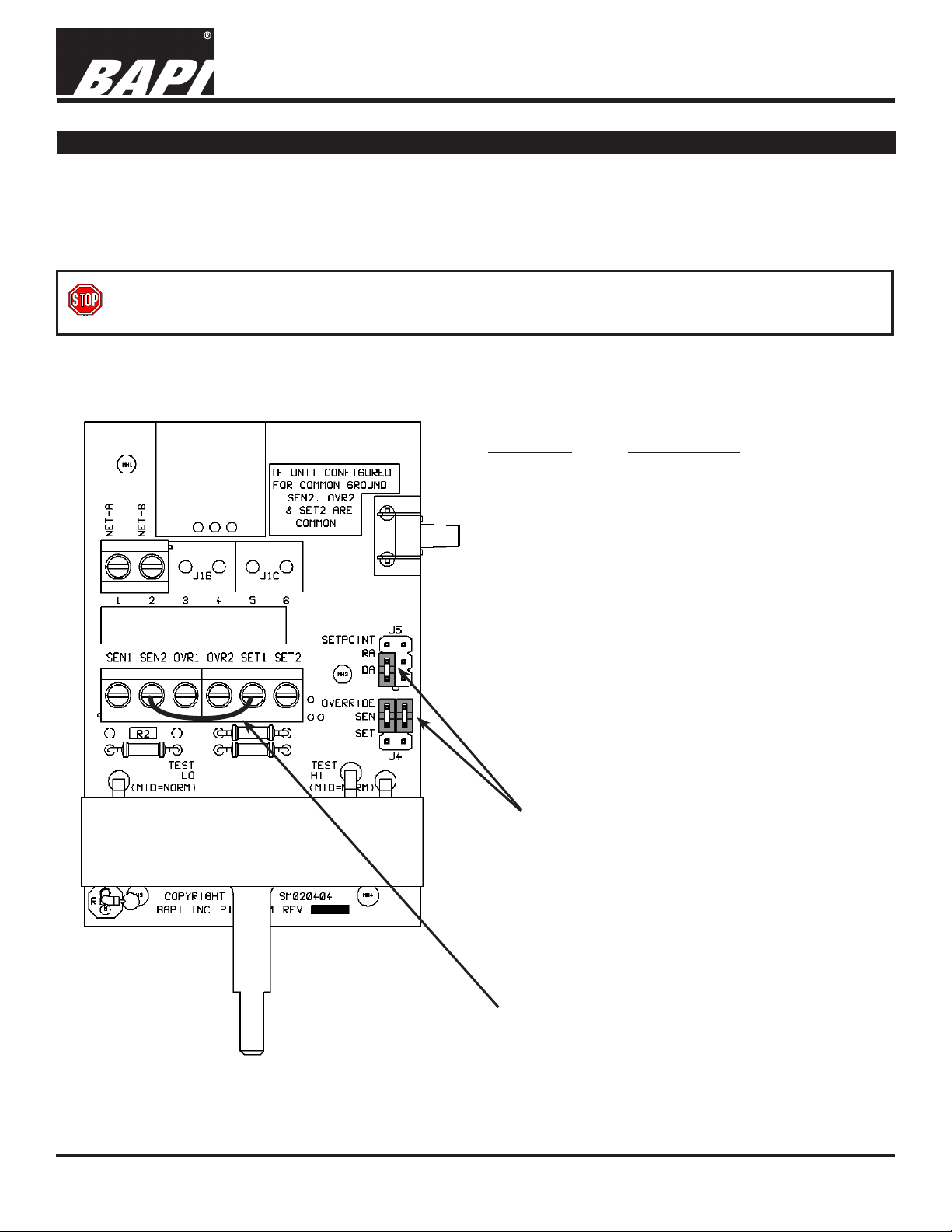
Fig. 2: Mounting hardware is provided
for both J-Box and drywall installation
(J-Box installation shown)
6. Pull the wire through the hole in the base plate.
7. Secure the base to the drywall anchors using the #6 x 1 inch mounting screws provided.
8. Terminate the unit according to the guidelines in the Termination section.
9. Attach Cover by latching it to the top of the base, rotating the cover down and snapping it into place. Secure the cover
by backing out the lock-down screws using a 1/16” Allen wrench until they are ush with the bottom of the cover.
NOTE: In a wall-mount application, the mixing of room air and air from within the wall cavity can lead to erroneous
readings, condensation, and premature failure of the sensor. To prevent this condition, plug the conduit hole with
insulation in the junction box.
Specications subject to change without notice.
1 of 3
Page 2
BAPI-Stat 4S LNX Room Sensor
(BA/LNX-BS4-SP2O, BA/LNX-B4O & BA/LNX-B4)
Installation & Operating Instructions
37498_BS4S_NoDisplay_LNX
Termination
BAPI recommends using twisted pair of at least 22AWG and sealant lled connectors for all wire connections. Larger
gauge wire may be required for long runs. All wiring must comply with the National Electric Code (NEC) and local codes.
Do NOT run this device’s wiring in the same conduit as AC power wiring. BAPI’s tests show uctuating and inaccurate
signals are possible when AC power wiring is in the same conduit as the signal lines. If you are experiencing any of these
difculties, please contact your BAPI representative.
BAPI recommends wiring the product with power disconnected. Proper supply voltage, polarity and wiring
connections are important to a successful installation. Not observing these recommendations may damage the
product and void the warranty.
TERMINAL DESCRIPTION
SEN1
................... Temperature Output Signal
to Controller Sensor Input
rev.02/07/17
SEN2 ................... Connected to “SET1” Terminal Via
Factory Installed Jumper
.................... Not Used
OVR1
OVR2 .................... Not Used
SET1 .................... Connected to “SEN2” Terminal Via
Factory Installed Jumper
.................... Temperature Output Signal Ground
SET2
to Controller Ground
Factory installed shunt jumpers.
Must be in these positions.
Fig. 3:
Circuit board
Factory installed jumper between “SET1” and
“SEN2” for units with temperature setpoint
adjustment. Jumper must be in this position.
(Units without setpoint adjustment do not have
the jumper.)
Specications subject to change without notice.
2 of 3
Page 3

BAPI-Stat 4S LNX Room Sensor
(BA/LNX-BS4-SP2O, BA/LNX-B4O & BA/LNX-B4)
Installation & Operating Instructions
37498_BS4S_NoDisplay_LNX
Setpoint and Override Operation
TEMPERATURE SETPOINT:
When the Temperature Setpoint Slider at the bottom of the unit is moved left or right, the temperature setpoint will
change within the ±2°F setpoint range.
OCCUPANCY OVERRIDE:
When the Override Button at the side of the unit is pressed, a dry resistance of less than 1 ohm appears across the
temperature sensor output terminals (“SEN1” to “SEN2”).
Specications
rev.02/07/17
Temperature Sensor:
10K-2 Thermistor for Units with Temperature Setpoint
11K-2 Thermistor for Units without Temperature Setpoint
±0.36°F Accuracy for 10K-2 and 11K-2 Thermistors
Override Output:
Momentarily shorts the temperature sensor output
terminals (“SEN1” and “SEN2”)
Wiring:
1 or 2 pair of 16 to 22 AWG
Mounting:
Standard 2”x4” J-box or drywall mount
- screws provided
Environmental Operation Range:
32 to 122 °F (0 to 50 °C)
0 to 95%, non-condensing
Material & Rating:
ABS Plastic, UL94, V-0
Certications:
RoHS and CE
Troubleshooting
POSSIBLE PROBLEM: POSSIBLE SOLUTIONS:
Temperature reading is incorrect
- Verify that the input is set up correctly in the controller’s and building
automation software.
- Check wiring for proper termination and check for opens or shorts.
- Check that the Thermistor temperature sensor inside the unit is working
correctly. Do this by measuring the room temperature at the sensor’s
location using an accurate temperature standard. Then disconnect the
temperature sensor wires (terminals “SEN1” and “SEN2”) and measure the
temperature sensor’s resistance across the “SEN1” and “SEN2” terminals
with an ohmmeter. Compare the temperature sensor’s measured resistance
to the 10K-2 Thermistor Temperature/Resistance table on the BAPI website.
(Units without setpoint have a 11K-2 Thermistor rather than a 10K-2
Thermistor. For these units, use the 10K-2 Temperature/Resistance table but
add 1,000 Ohms to the value in the table to obtain the 11K-2 table value.)
If the measured resistance varies by more than 5% from the temperature
table, call BAPI technical support. To view the temperature table, go to the
BAPI website (www.bapihvac.com), click on “Resource Library” and “Sensor
Specs”, then click on the type of sensor you have.
Setpoint reading is incorrect
- Make sure that the jumper is connected between the “SET1” and “SEN2”
terminals.
Override is not working correctly - Check that the resistance across the “SEN1” and “SEN2” terminals is less
than 5Ω when the override button is pushed.
Specications subject to change without notice.
3 of 3
 Loading...