

Page 1
BAPI-Stat 4 Sensor, w/Display, Button Setpoint, Fan or System Mode Control
Product Identication and Overview
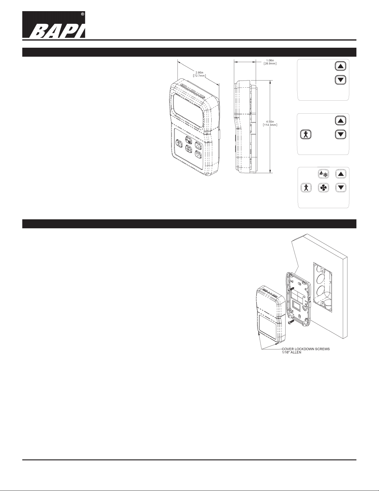
The BAPI-Stat 4M room temperature sensor
features a large format LCD and pushbutton
setpoint adjustment. Additonal options include
pushbutton override, fan speed and mode
adjustments.
The setpoint is available as a resistance or
voltage output. The override is a momentary
closure signal that can be congured in parallel
with the sensor or setpoint, or as a separate
momentary or latching contact output. A 3.5mm
(1/8”), RJ11 or RJ22 communication jack can
also be mounted in the unit’s base to provide
direct access to the network.
BA/BS4M Temperature Sensor
Installation & Operating Instructions
rev. 01/18/1625188_ins_BS4M
Fig. 2: 2 Button Unit
Fig. 1: BAPI-Stat 4M
with optional Setpoint,
Override, Fan and Mode
Control.
Note: BAPI-Stat 4M shown with
ve buttons. Two, three or ve
buttons may be present. See “Front
Panel & Control” section.
Mounting
JUNCTION BOX
1. Pull the wire through the wall and out of the junction box, leaving about 6 inches free.
2. Pull the wire through the hole in the base plate.
3. Secure the base to the box using the #6-32 x 1/2 inch mounting screw provided.
4. Terminate the unit according to the guidelines in the Termination section.
5. Attach Cover by latching it to the top of the base, rotating the cover down
and snapping it into place.
6. Secure the cover by backing out the lock-down screws using a 1/16” Allen
wrench until they are ush with the bottom of the cover.
DRYWALL MOUNTING
1. Place the base plate against the wall where you want to mount the sensor.
2. Using a pencil, mark out the two mounting holes and the area where the
wires will come through the wall.
3. Drill two 3/16” holes in the center of each marked mounting hole. Insert a
drywall anchor into each hole.
4. Drill one 1/2” hole in the middle of the marked wiring area.
5. Pull the wire through the wall and out the 1/2” hole, leaving about 6” free.
6. Pull the wire through the hole in the base plate.
7. Secure the base to the drywall anchors using the #6 x 1 inch mounting screws provided.
8. Terminate the unit according to the guidelines in the Termination section.
9. Attach Cover by latching it to the top of the base, rotating the cover down and snapping it into place. Secure the cover
by backing out the lock-down screws using a 1/16” Allen wrench until they are ush with the bottom of the cover.
Fig. 5: Mounting hardware is provided
for both J-Box and drywall installation
(J-Box installation shown)
Fig. 3: 3 Button Unit
Fig. 4: 5 Button Unit
NOTE: In a wall-mount application, the mixing of room air and air from within the wall cavity can lead to erroneous
readings, condensation, and premature failure of the sensor. To prevent this condition, plug the conduit hole with
insulation in the junction box.
Specications subject to change without notice.
1 of 8
Page 2
BAPI-Stat 4 Sensor, w/Display, Button Setpoint, Fan or System Mode Control
BA/BS4M Temperature Sensor
Installation & Operating Instructions
rev. 01/18/1625188_ins_BS4M
Termination
BAPI recommends using twisted pair of at least 22AWG and sealant lled connectors for all wire connections. Larger
gauge wire may be required for long runs. All wiring must comply with the National Electric Code (NEC) and local codes.
Do NOT run this device’s wiring in the same conduit as AC power wiring. BAPI’s tests show uctuating and inaccurate
signals are possible when AC power wiring is in the same conduit as the signal lines. If you are experiencing any of these
difculties, please contact your BAPI representative.
BAPI recommends wiring the product with power disconnected. Proper supply voltage, polarity and wiring
connections are important to a successful installation. Not observing these recommendations may damage the
product and void the warranty.
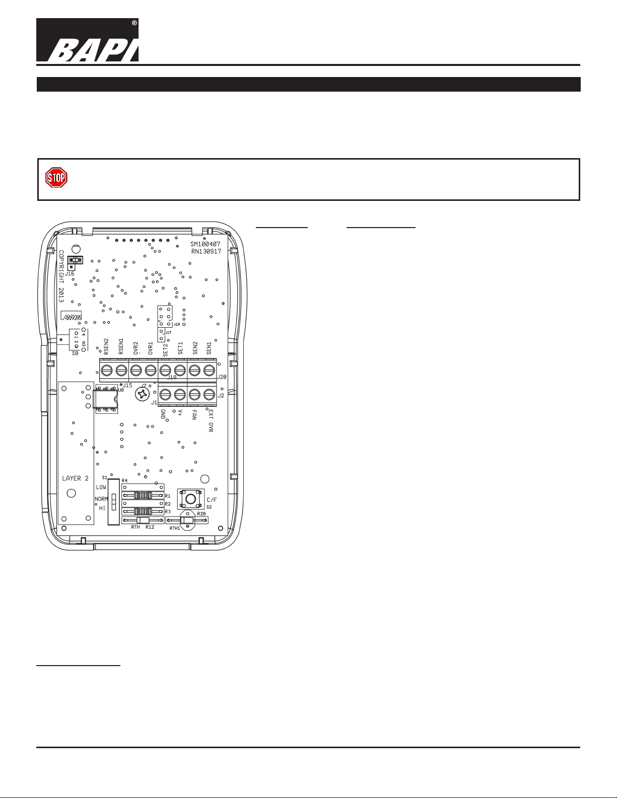
TERMINAL DESCRIPTION
GND ........................Power Supply Ground (Common to the controller)
V+
........................... Power Supply Hot (See specications for voltage
details)
.........................Fan Speed/System Mode (Resistive Output)
FAN
EXT OVR
SEN1 & SEN2
SET1 & SET2 ......... A) Setpoint output per order (resistive). *If the unit
B) Setpoint output per order (voltage). SET1 is
OVR1 & OVR2
Fig. 6: BAPI-Stat 4M Circuit Board
*Grounding Note:
Common Ground (-CG) or Differential Ground (-DF) congurations are selected per order. The Differential Ground
conguration (-DF) indicates that SEN2, SET2, OVR2 and RSEN2 must all be wired separately (No internal common
connection). The Common Ground conguration (-CG) indicates that SEN2, SET2, OVR2 and RSEN2 are connected to
GND internally (All internally common). This is true of all Common Ground units except when ordered with the Override as
a Latching Switch option (-L#). In this case, OVR2 is isolated and not internally connected to SEN2, SET2 and RSEN2.
RSEN1 & RSEN2
................BAPI-Man Occ/Un-Occ indicator Input.
Ground terminal to ll in the BAPI-Man icon for
Occupied.
........Sensor output per order (resistive). No polarity. *If
the unit is a common ground conguration (-CG),
see “Grounding Note” below.
is a common ground conguration (-CG), see
“Grounding Note” below.
“+”, SET2 is “-”. *If the unit is a common ground
conguration (-CG), see “Grounding Note”
below.
........Override output (Dry contact) The contact can be
ordered as a momentary shunt across the sensor
(-N) or as a momentary shunt across the setpoint
(-P) or as a separate momentary contact (-J) or
as a separate latching contact (-L#). *If the unit
is a common ground conguration (-CG), see
“Grounding Note” below.
... Remote sensor option (-ES). No polarity. *If the
unit is a common ground conguration (-CG),
see “Grounding Note” below. A 10K-2 thermistor
sensor must be ordered separately and the
temperature value is displayed on the LCD. Note:
If a temperature reading is needed at the controller,
then a second sensor must be ordered and wired
independently.
Specications subject to change without notice.
2 of 8
Page 3
BAPI-Stat 4 Sensor, w/Display, Button Setpoint, Fan or System Mode Control
Low Temp (40° F)
High Temp (105°F)
3000Ω Thermistor 7.87KΩ (39.8°F) 1.5KΩ (106.8°F)
10K-3(11K) Thermistor 7.32KΩ (43.7°F) 3.65Ω (105.2°F)
HCF 5KΩ 10KΩ 15KΩ 20KΩ 25KΩ 30KΩ
Option Heat Cool Auto Off
Option OFF AUTO LO MED HI ON
XLD 5KΩ 10KΩ 15KΩ 20KΩ 25KΩ
X02 2KΩ 4KΩ 6KΩ 8KΩ 10KΩ
X06 6.5KΩ 8.5KΩ 10.5KΩ 12KΩ
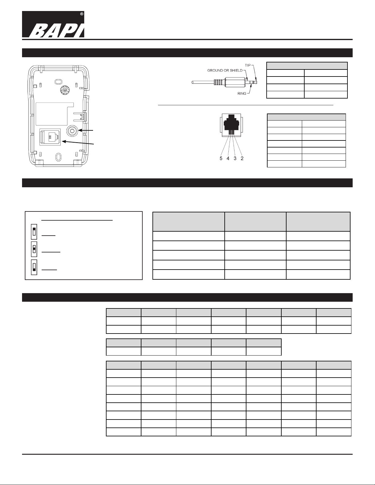
Optional Communication Jack Wiring
BA/BS4M Temperature Sensor
Installation & Operating Instructions
rev. 01/18/1625188_ins_BS4M
Fig. 7:
Back Plate
Comm.
Jack
Locations
C35L
C11L/
C22L
Fig. 8: C35L
Comm. Jack
(3.5mm plug
shown for
clarity)
Fig. 9:
C11/C22
Comm.
Jack
C35L Comm. Jack Wiring
Location WIRE COLOR
Ground Black
Tip White
Ring Red
C11L/C22L Comm. Jack Wiring
PIN # WIRE COLOR
1 Not Connected
2 Black
3 Red
4 Yellow
5 Green
6 Not Connected
Optional Test and Balance Switch (S1)
On the Test and Balance Switch, the NORM position allows the real sensor to be monitored. The HIGH position forces the
output to a very hot reading and the LOW position forces a very cold reading (see Table below).
Test and Balance Switch (S1)
LOW: Sets the sensor value low
Sensor Type
Resistance Value
Resistance Value
1000Ω RTD 1.02KΩ (41.20°F) 1.15KΩ (101.5°F)
NORM: Sensor operates normally
HIGH: Sets the sensor value high
Optional Fan Speed and System Mode Control
The unit is available with
optional Fan Speed and
Option Heat/Auto Off /Auto Cool/Auto Heat/On Off/On Cool/On
System Mode Control.
The resistive outputs for
H01 0Ω 2KΩ 4KΩ 6KΩ 8KΩ 10KΩ
the various options is
shown in the table at right.
The option is selected at
H02 5KΩ 10KΩ 15KΩ 20KΩ
the time of order and the
resistive value is output to
the FAN terminal.
X01 4.89KΩ 2.33KΩ 10.63KΩ 13.24KΩ 16.33K
X03 5KΩ 10KΩ 15KΩ
X05 4.89KΩ 2.33KΩ 15.8KΩ
X07 5KΩ 15KΩ
X08 12.68KΩ 11.86KΩ 13.86KΩ
10K-2 Thermistor 30.1KΩ (34.9°F) 4.75Ω (109.1°F)
10K-3 Thermistor 26.7KΩ (35.9°F) 5.11KΩ (108.4°F)
Specications subject to change without notice.
3 of 8
Page 4

BAPI-Stat 4 Sensor, w/Display, Button Setpoint, Fan or System Mode Control
Front Panel & Control Descriptions
A display is standard for all BA/BS4M
units. It is available with an optional
override button, setpoint buttons, fan
control or system control buttons or any
option combination. Fig. 10 shows a fully
featured sensor.
NUMERICAL DISPLAY:
The default display shows current
temperature. When the up/down buttons
are pushed, then the display will show
and adjust the current setpoint and hold
the display for 3 to 4 seconds. The unit
can also be set up to display setpoint
only or for setpoint lockout. See “Optional
Technicians Adjustments” section.
BAPI-MAN ICON:
The BAPI-Man Icon shows the status of
the room – Solid for Occupied, Hollow for
“Unoccupied” (Fig. 11).
Note: The unit must receive a
conrmation (ground) signal on the “EXT OVR”
terminal for the BAPI-Man to remain visible on the
screen. Pressing the Override button will light the
BAPI-Man icon; however, if no conrmation signal is
received, then the BAPI-Man will go blank (disappear)
after 5 seconds.
Upon receiving a rst conrmation (ground) signal
on the “EXT OVR” terminal, the BAPI-Man will show
occupied (Solid). The BAPI-Man will then show
unoccupied (Hollow) whenever the conrmation signal
is removed and occupied when the signal is returned.
The only way to blank the BAPI-Man from the display
at this point is to cycle power.
Fan and Speed Indicator
Occupied or Unoccupied Icon
Automatic System Mode
BA/BS4M Temperature Sensor
Heat Mode
Cool Mode
System Mode Button
Override Button
Fan Speed Button
Fig. 10: BAPI-Stat 4M unit with Override, Setpoint, Fan
Note: BAPI-Stat 4M shown with ve buttons. Two,
three or ve buttons may be present.
Solid
equals
“Occupied”
Fig. 11: BAPI-Man Icon
Installation & Operating Instructions
& System Buttons.
Hollow
equals
“Unoccupied”
rev. 01/18/1625188_ins_BS4M
Engineering Units
Temperature Display
in .5 Increments
Override On
Override Off
Setpoint Up/Down
Buttons
Fan Speed
Low
Fan Speed
Medium
Fan Speed
High
Fig. 12: Fan Speed
Indicator
FRONT PANEL BUTTONS
SETPOINT:
When pressed, the setpoint will display for three to four seconds. When pressed again, the setpoint will change
in one degree increments. It will only change within the setpoint range that was ordered.
OVERRIDE:
When the override button is pressed, the BAPI-Man will be displayed as “Solid” for 3-5 seconds and the override
output will shunt or short for 3 seconds depending on the override option selected. (-N Option = Momentary
Temperature Sensor Shunt to <15Ω, -P Option = Momentary Setpoint Shunt to <15Ω, -J Option = Momentary Override as
a Separate Shorting Contact Output, -L# Option = Override as a Latching Switch, See “Latching Override Operation” on
pg. 5.) If the occupied input (EXT OVR) terminal is grounded, then the BAPI-Man will stay lled in, indicating an occupied
state. If the input is open, then the BAPI-Man will revert to hollow, indicating unoccupied (or the icon will disappear
completely if there has never been a ground on the EXT OVR terminal).
MODE:
Cycles through ‘HEAT’, ‘OFF’ and ‘COOL’.
FAN:
Cycles through ‘AUTO’, ‘ON’ and Fan Speed (see Fig. 12).
Specications subject to change without notice.
4 of 8
Page 5

BAPI-Stat 4 Sensor, w/Display, Button Setpoint, Fan or System Mode Control
BA/BS4M Temperature Sensor
Installation & Operating Instructions
rev. 01/18/1625188_ins_BS4M
Optional Technician Adjustments (The sensor set-up is factory set per your order. Set-up adjustments are not required)
The unit is shipped ready to install per the order and does not requires any special setup or programming. The following
Setup or Program Menu Changes are available if the installer decides to change the factory settings. Pushing the button
(S2) on the lower right side of the termination board allows the user to change the display from Celsius to Fahrenheit and
back again (See Fig. 6).
ENTERING PROGRAM MODE AND MAKING CHANGES:
1. Remove cover and install the shunt jumper across the J16 pins (see Fig. 13).
2. Use the Up and Down Setpoint Pushbuttons on the front of the sensor to advance
to the parameter you wish to adjust. (Moves up or down from page to page or from
setting to setting.)
3. Push the Override Pushbutton on the front of the unit to select the menu adjust
Jumper Off
Run Mode
parameter. This selects the currently displayed menu.
4. Use the Up and Down pushbuttons to adjust the parameter
Fig. 13: J16 Program
5. Push the Override Pushbutton to select the newly adjusted parameter value.
6. You can quit by removing J16 or move to the next parameter using the Up/Down Setpoint buttons.
Note: If your unit does not have the necessary front Up/Down/Override buttons for
adjustment you can remove the board from the housing and use the three
buttons that are on the back of the board. Removing the board requires
removing the centered board mounting screw. The buttons are identied as S3
= Enter (Override), S5 = Up Adjust and S6 = Down Adjust. (See Fig. 14) After
adjustment, place the board back into the cover and insert the center mounting
screw. Do not over tighten.
Jumper On
Program Mode
Jumper
MODE MENUS:
The setup mode consists of menu pages P1 through P6 for conguring the sensor.
The following adjustments can be done with the program jumper J16 installed.
P1 = Temperature offset: Adjust Up or Down, -5 to 5° in 0.1° increments
P2 = Setpoint Lockout: Adjust the value to dene the Setpoint mode
0 = Enable Setpoint adjustment (Normal mode)
1 = Disable Setpoint adjustment (No setpoint adjust)
Enter
2 = Display Setpoint Only (No room temperature displayed)
3 = No Setpoint Displayed (Rarely used with pushbutton setpoint units)
P3 = Latching Display (see Fig. 15)
-1 = Override Disabled
0 = Momentary Contact, Hollow Man/Solid Man (Typically the normal setting)
1 = Latching Contact: Off/On, No Fan/Fan, Solid Man
2 = Latching Contact: Off/On, No Fan/Fan, No BAPI-Man
3 = Latching Contact: Off/On, Solid Man
4 = Latching Contact: Off/On, No BAPI-Man
Fig. 14: Setup Switch
locations on the circuit board.
5 = Latching Contact: On/Off, Fan/No Fan, Solid Man
6 = Latching Contact: On/Off, Fan/No Fan, No BAPI-Man
7 = Latching Contact: On/Off, Solid Man
8 = Latching Contact: On/Off, No BAPI-Man
9 = Latching Contact: Hollow Man/Solid Man
10 = Non-Latching
See “Latching Override Operation” and “Momentary Override Operation” descriptions for further details.
P4 = Temperature Display: Adjust value to the display increments desired
0 = Display in whole digits only
1 = Display in 0.5° increments, F or C as chosen on switch S2
2 = Display in 0.1° increments, F or C as chosen on switch S2
P5 = Setpoint Display Low: Adjust the Low temperature of the desired setpoint range between -9 to 99°.
P6 = Setpoint Display High: Adjust the High temperature of the desired setpoint range between -9 to 99°.
Up
Down
5 of 8
Page 6
BAPI-Stat 4 Sensor, w/Display, Button Setpoint, Fan or System Mode Control
BA/BS4M Temperature Sensor
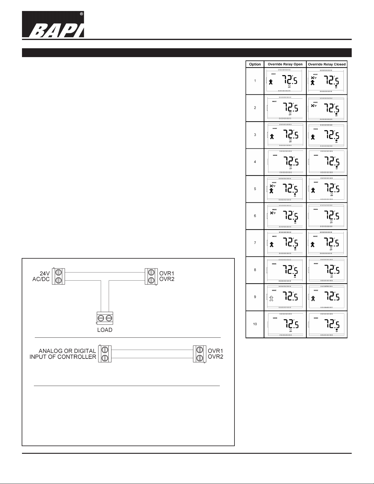
Latching Override Operation
The unit can be ordered with an “Override as a Latching Switch” by selecting
the -L# option. The # (1-10) represents the display the user may want to use
and is shown below. This can be changed by a technicians adjustment.
In the “Override as Latching Switch” Option, pressing the Override button
closes the override relay contacts (Terminals OVR1 & OVR2). They will remain
closed until the “Override” button is pressed again, then they will open and
remain open until the Override button is pressed again. See Fig. 16 below for
examples of “Override as a Latching Switch” circuits.
Ten display options (Fig. 15) are available to indicate when the latching relay
is open and when the latching relay is closed. Note: If one of the “Fan Speed/
Mode” options is selected from the ordering grid, then you MUST use the
latching display Option 9.
BAPI-MAN ICON
On Options 2, 4, 6, 8 & 10, the BAPI-Man Icon is disabled and will not show on
the display, even when the Override button is pushed.
On Options 1, 3, 5 & 7, the BAPI-Man Icon is lled or solid for 3 to 5 seconds
after the Override button is pushed, but it will only remain solid or lled when
there is a ground signal to the EXT OVR terminal of the unit.
For Option 9, the BAPI-Man Icon stays lled or solid when the relay is closed
and hollow when the relay is open.
For Option 10, the BAPI-Man Icon is disabled but the “ON” or “OFF” Dot on the
display is controlled by the EXT OVR terminal. When there is a ground signal at
the EXT OVR terminal, the “ON” dot is lit. Otherwise the “OFF” and hollow dot
are lit. Note: The Override Terminals OVR1 and OVR2 are NOT latching in
Option 10. These terminals close MOMENTARILY in this option.
Installation & Operating Instructions
rev. 01/18/1625188_ins_BS4M
Latching Switch with
External Load Circuit
Latching Switch as Direct Controller Input Circuit
Fig. 16: Latching Switch Wiring Diagrams
In the “Override as Latching Switch” conguration, terminals OVR1 &
OVR2 act as a latching switch with a maximum capacity of 24 VAC/VDC
at 800 mA resistive. Pressing the Override button latches or unlatches
the OVR1 & OVR2 terminals. These diagrams show how to wire the
latching switch with an External Load and as a Direct Controller Input
Fig. 15: Latching Switch Display Options
The 10 “Override as a Latching Switch”
display options are shown above for
when the relay is open and when the
relay is closed.
Note 1: If the unit is ordered with “Fan
Speed/Mode” Options, then you must
use the latching display Option 9.
Note 2: On Options 1, 3, 5 & 7, the
BAPI-Man Icon is lled or solid for 3 to
5 seconds after the Override button is
pushed, but it will only remain solid or
lled when there is a ground signal to
the EXT OVR terminal of the unit.
6 of 8
Page 7

BAPI-Stat 4 Sensor, w/Display, Button Setpoint, Fan or System Mode Control
BA/BS4M Temperature Sensor
Installation & Operating Instructions
rev. 01/18/1625188_ins_BS4M
Momentary Override Operation (Non-Latching)
When the Override pushbutton is pressed, the BAPI-Man (Fig. 11) will be displayed as “Solid” for 3-5 seconds and the
override output will shunt or short for 3 seconds depending on the override option selected. The various options are
described below.
-N Option = Momentary Temperature Sensor Shunt to < 15Ω
-P Option = Momentary Setpoint Shunt to <15Ω
-J Option = Momentary Override as a Separate Shorting Contact Output on OVR1 & OVR2
BAPI-MAN ICON:
The BAPI-Man Icon shows the status of the room – Solid for Occupied, Hollow for “Unoccupied” (Fig. 11). The unit must
receive a conrmation (ground) signal on the “EXT OVR” terminal for the BAPI-Man to remain visible on the screen.
Pressing the Override button will light the BAPI-Man icon; however, if no conrmation signal is received, then the BAPIMan will go blank (disappear) after 5 seconds. Upon receiving a rst conrmation (ground) signal on the “EXT OVR”
terminal, the BAPI-Man will show occupied (Solid). The BAPI-Man will then show unoccupied (Hollow) whenever the
conrmation signal is removed and occupied when the signal is returned. The only way to blank or remove the BAPI-Man
from the display after receiving a conrmation signal is to cycle power.
General Diagnostics
POSSIBLE PROBLEM: POSSIBLE SOLUTIONS:
Temperature reading is incorrect - Verify that the input is set up correctly in the controller’s and building
automation software.
- Check wiring for proper termination and check for opens or shorts.
- Measure the room temperature at the sensor’s location using an accurate
temperature standard. Disconnect the temperature sensor wires and
measure the temperature sensor’s resistance across the sensor output
pins with an ohmmeter. Compare the temperature sensor’s resistance
to the appropriate temperature sensor table on the BAPI website. If the
measured resistance varies by more than 5% from the temperature table,
call BAPI technical support. To view the temperature table, go to the BAPI
website (www.bapihvac.com), click on “Resource Library” and “Sensor
Specs”, then click on the type of sensor you have.
- If the unit has a test and balance switch, make sure that it is in the correct
position.
Setpoint reading is incorrect - Make sure that the setpoint output is correct. Remove the setpoint output
wire and check the output for the correct resistance or voltage output. See
the product label for your specic range.
Override is not working correctly - Check that the resistance across the override output is less than 5Ω when
the override is pushed.
Fan Mode not correct - Make sure that the fan mode output is correct. Remove the fan mode
output wire and check the output for the correct resistance. See the
product label for your specic range and compare it to the resistance chart
at the bottom of page 3. Don’t forget to reconnect the wire.
Specications subject to change without notice.
7 of 8
Page 8

BAPI-Stat 4 Sensor, w/Display, Button Setpoint, Fan or System Mode Control
BA/BS4M Temperature Sensor
Installation & Operating Instructions
Specications
Power for 5 VDC Power Units:
0 to 5 VDC Setpoint or Resistive Setpoint ....5V ±1% (5 VDC nominal, Input regulation affects accuracy)
Power for 24 VDC Power Units:
0 to 5 VDC Setpoint or Resistive Setpoint ...9 to 40 VDC (24 VDC nominal)
0 to 10 VDC Setpoint or Resistive Setpoint ..15 to 40 VDC (24 VDC nominal)
Any Allowed Setpoint ....................................15 to 28 VAC (24 VAC nomimal)
Note: AC power requires a separate pair of shielded wires
Power Consumption: .....................................7 mA max DC; .17 VA maximum AC
Wiring: ................... See Wiring & Termination Section, 22 to 14AWG
Mounting: .............. Standard 2 x 4” box or drywall direct, Screws provided
Outputs:
Passive Sensor....See order grid for thermistor or RTD
Thermistor, ±0.36ºF (±0.2ºC), [XP] ±0.18ºF (±0.1ºC)
Platinum RTD, ±0.12%, [A] ±0.06%
Nickel RTD, 1000Ω @70ºF, JCI curve
External Sensor ...10K-2 thermistor (-ES), (Purchased separately) Wired 25’ maximum from sensor
Setpoint ...............Resistive per order or voltage (0 to 10VDC limit per order)
Isolated Contact ..24VDC @500mA resistive
Inputs: ....................Dry contact (24V, <1mA)
Occupied .............EXT OVR “Grounded”
Unoccupied .........EXT OVR “Open to Ground”
Display: .................LCD, Overall, 2”W x 1.1”H (Temp/Setpoint/Occupied)
LCD ....................3.5 Digits @0.6”H
Occ/Unocc ..........BAPI-Man Icon, (Filled in man is occupied)
Display Limits ......1.0º, 0.5° and 0.1° (F/C) increments, Setpoints in 1º steps
Range .................-40 to 185°F (-40 to 85°C)
Display Setup ......Temp. & Setpoint, Temp. only, or Setpoint only, ºF or ºC
Optional ............... Fan Speed, System Mode, Override
Button Options: .... Factory set options
Setpoint ..............Up & Down buttons
Override .............. Pushbutton
Override .............. Factory set to Momentary shunt across sensor, Momentary shunt across setpoint,
Momentary isolated contact or Latching isolated contact
Fan Speed ...........Off, Auto, Lo, Med, Hi
System Mode ......Heat/Off/Cool, Auto/On Fan
Setup Options:
Offset ...................±5º
Temp Display .......Display in ºF or ºC
Setpoint ...............Disabled or Setpoint display only
Resolution ...........Display in 1.0°, 0.5º or 0.1º increments
Other Options:
Comm. jack .........3.5mm phone jack, 3 wires (-C35) • RJ11 jack, 4 wires (-C11) • RJ22 jack, 4 wires (-C22)
Test & Balance .... Three position switch (-TB), (High Temp/Normal/Low Temp)
Common Ground .Internal common connection (-CG)
Differential GND. .Each output terminal is isolated (-DF)
Environmental Ambient:
Temperature ........32 to 122ºF (0 to 50ºC)
Humidity ..............0 to 95% RH Non-condensing
Storage ................32 to 185°F (0 to 85°C)
Encl. Material: ....... ABS Plastic, UL94V-0
Agency: .................RoHS, CE* (*Units with passive Thermistors 20KΩ and smaller are CE compliant.)
Specications subject to change without notice.
rev. 01/18/1625188_ins_BS4M
8 of 8
 Loading...