

Page 1
BAPI-Stat 4 Room Humidity Sensor (BA/B4-H200 Series)
24595_ins_BAPI_4_room_humidity
Overview
The BAPI-Stat 4 Style room unit is available as a humidity only sensor or as
a combination temperature and humidity sensor with optional LCD display,
temperature setpoint adjustment and occupant override. It is available with the
entire line of BAPI temperature sensors.
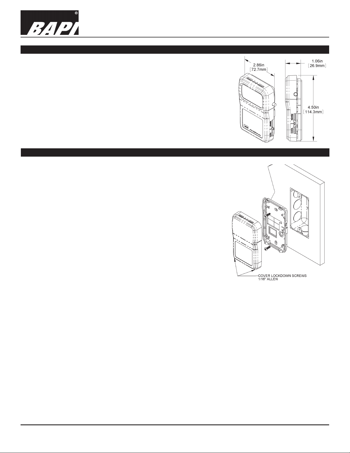
Fig 1: BAPI-Stat 4
Room Humidity with
Setpoint & Override
Mounting
Mounting hardware is provided for both junction box and drywall installation
(junction box installation shown).
JUNCTION BOX
1. Pull the wire through the wall and out of the junction box, leaving about six
inches free.
2. Pull the wire through the hole in the base plate.
3. Secure the plate to the box using the #6-32 x 1/2 inch mounting screws
provided.
4. Terminate the unit according to the guidelines in the Termination section.
5. Attach cover by latching it to the top of the base, rotating down and
snapping into place.
6. Secure the cover by backing out the lock-down screws using a 1/16” Allen
wrench until they are ush with the bottom of the cover.
Installation & Operating Instructions
rev. 12/15/17
DRYWALL MOUNTING
1. Place the base plate against the wall where you want to mount the sensor.
Fig 2: Mounting to a Junction Box
2. Using a pencil mark out the two mounting holes and the area where the
wires will come through the wall.
3. Drill two 3/16” holes in the center of each marked mounting hole. Insert a drywall anchor into each hole.
4. Drill one 1/2” hole in the middle of the marked wiring area.
5. Pull the wire through the wall and out of the 1/2” hole, leaving about six inches free.
6. Pull the wire through the hole in the base plate.
7. Secure the base to the drywall anchors using the #6 x 1 inch mounting screws provided.
8. Terminate the unit according to the guidelines in the Termination section.
9. Attach cover by latching it to the top of the base, rotating the cover down and snapping it into place. Secure the cover
by backing out the lock-down screws using a 1/16” Allen wrench until they are ush with the bottom of the cover.
NOTE: In any wall-mount application, the wall temperature and the temperature of the air within thewall cavity can
cause erroneous readings. The mixing of room air and air from within the wall cavity can lead to condensation, erroneous
readings and premature failure of the sensor. To prevent these conditions, seal the conduit leading to the junction box or
ll the box with insulation.
Specications subject to change without notice.
1 of 5
Page 2
BAPI-Stat 4 Room Humidity Sensor (BA/B4-H200 Series)
Installation & Operating Instructions
24595_ins_BAPI_4_room_humidity
Terminations
BAPI recommends using twisted pair of at least 22 AWG. Larger gauge wire may be required for long runs. All wiring must
comply with the National Electric Code (NEC) and local codes. Do NOT run this device’s wiring in the same conduit as
AC power wiring of NEC class 1, NEC class 2, NEC class 3 or with wiring used to supply highly inductive loads such as
motors, contactors and relays. BAPI’s tests show that uctuating and inaccurate signal levels are possible when AC power
wiring is present in the same conduit as the signal lines.
BAPI recommends wiring the product with power disconnected. Proper supply voltage, polarity, and wiring
connections are important to a successful installation. Not observing these recommendations may damage the
product and will void the warranty.
4 to 20 mA Output Unit Termination
Terminal Function
OVR1 & OVR2
If unit is a common (-CG) model, see Note below.
SET1 & SET2 .... Setpoint Output
If unit is a common (-CG) model, see Note below.
SEN1 & SEN2 ... Sensor Output – Resistive Output.
(Semiconductor: SEN1=+, SEN2=-)
If unit is a common (-CG) model, see Note below.
EXT-OVR ........... Allows remote control of the LCD indicator for
VOUT
................. Not Used
...................... Power, see specications section for details
V+
................... 4 to 20 mA Humidity Signal [to analog input of
GND
... Override Output – Dry Contact Switch
occupancy, and is activated by logic LOW or power
supply ground at this terminal.
controller]
rev. 12/15/17
0 to 5 VDC, 0 to 10 VDC & 2 to 10 VDC Output Unit Termination
Terminal Function
OVR1 & OVR2
If unit is a common (-CG) model, see Note below.
SET1 & SET2 .... Setpoint output.
If unit is a common (-CG) model, see Note below.
SEN1 & SEN2 ... Sensor Output – Resistive Output.
(Semiconductor: SEN1=+, SEN2=-)
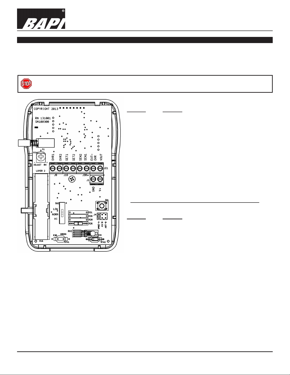
Fig 3: Circuit Board
Notes:
On Common Ground (-CG) Models: On the common (-CG) models, terminals “OVR2”, “SEN2”, and “SET2” are connected
together internally but they are not connected to Ground “GND”. If you intend to use “GND” as common, then a jumper must
be added from terminal “GND” to “SEN2”. This is only allowed on Voltage Output models. Do not install this jumper on 4 to 20
mA Output models.
On Differential Ground (-DF) Models: All terminals are independent.
If unit is a common (-CG) model, see Note below.
EXT-OVR ........... Allows remote control of the LCD indicator for
VOUT
................. Voltage Humidity Signal [to analog input of controller]
...................... Power, see specications section for details
V+
................... To controller power supply ground
GND
... Override Output – Dry Contact Switch
occupancy, and is activated by logic LOW or power
supply ground at this terminal.
2 of 5
Page 3

BAPI-Stat 4 Room Humidity Sensor (BA/B4-H200 Series)
Installation & Operating Instructions
24595_ins_BAPI_4_room_humidity
Optional Test Balance Switch (SW2)
The test and balance switch is used by the balancer to equalize the ow of air or water. It can also be used to verify sensor
termination in a point-to-point checkout of the control system. The “NORM” position allows the real sensor to be monitored.
“HI” position forces the output to a very hot reading and the “LOW” position forces the output to a very cold output (See T
Optional Test and Balance Switch (SW2)
LOW: Will set the sensor value low
NORM: Thermistor/RTD will operate normally
HI: Will set the sensor value high
Table 1: Test and Balance Resistance Values
Sensor Type Low Temp (40º F) Resistance High Temp (105º F) Resistance
1000Ω RTD 1.02KΩ (41.2º F) 1.15KΩ (101.5º F)
3000Ω Thermistor 7.87KΩ (39.8º F) 1.5KΩ (106.8º F)
10K-2 Thermistor 30.1KΩ (34.9º F) 4.75Ω (109.1º F)
10K-3 Thermistor 26.7KΩ (35.9º F) 5.11KΩ (108.4º F)
10K-3(11K) Thermistor 7.32KΩ (43.7º F) 3.65Ω (105.2º F)
Optional Technician Adjustments
Adjustments for Units with a Display
The optional technician adjustments allows a technician to set temperature and humidity offsets, °F or °C
display indication and which parameters are shown on the display. When the unit is powered up, pressing
switch SW1 will enter the user calibration adjustment mode (See Fig 4) and the LCD will show page zero, P0.
Fig 4: SW1
Calibration
Switch
The page numbers auto-scroll to P5 and then the unit returns to the normal run mode. Pressing SW1 when
any page number is displayed will show the calibration value that is associated with that page. The variable will
auto-scroll and will show all the allowed values for the selected page. Pressing SW1 when the variable value
you need is shown will record that value and return to showing page numbers.
rev. 12/15/17
able 1).
The
Parameter Page Designator Adjustment
Temperature Offset P0 ±5° in 0.1° increments. A high accuracy reference is recommended.
Humidity Offset P1 ±5% in 0.1% increments or R34 (When R34 is selected, humidity offset is set
by turning potentiometer R34, See Fig. 5 below.)
Display Units P2 °F or °C
Display RH to Temp Toggle Time P3 3 to 11 seconds
Display Resolution P4 0 = 0.5
1 = 0.1
Display Section P5 0 = Temperature, Humidity and Temperature Setpoint when active*
1 = Temperature and Temperature Setpoint when active*
2 = Humidity and Temperature Setpoint when active*
3 = Temperature, Humidity and Temperature Setpoint**
4 = Temperature and Temperature Setpoint**
5 = Humidity and Temperature Setpoint**
6 = Temperature Setpoint
7 = Temperature and Humidity**
8 = Temperature
9 = Humidity
* “When active” means when moving the setpoint slider.
** Display toggles through selections
.
Humidity Offset Potentiometer R34
Potentiometer R34 (Fig. 5) can be used to adjust the humidity output by ±5%. A high accuracy
humidity reference is recommended.
Fig 5: R34 %RH Adjustment Potentiometer
Humidity Output Selection
Moving the jumper on connector J4 will change the humidity output from 4 to 20mA, 0 to 5VDC or 0 to 10VDC.
Fig 6 shows the jumper in the 4 to 20mA position. The 0 to 10 VDC jumper is used for the 2 to 10 VDC signal if
an H212 or H312 was ordered.
Fig 6: Humidity Output Jumpers
Specications subject to change without notice.
3 of 5
Page 4

BAPI-Stat 4 Room Humidity Sensor (BA/B4-H200 Series)
24595_ins_BAPI_4_room_humidity
Optional Communications Jack Wiring
Male Jack shown for clarity
Fig 7: C35L Communications Jack
Installation & Operating Instructions
rev. 12/15/17
C11L/C22L Wiring
Comm Jack Pin Wire Color
1 Not Connected
2 Black
3 Red
4 Yellow
5 Green
6 Not Connected
Fig 8: C11L/C22L Communications Jack
C35L Front
C35L Back
C11L/C22L Front C11L/C22L Back
User Operation
Signies Temperature Setpoint
Signies Space Temperature
or Humidity Being Displayed
BAPI Man Icon
Display or Setpoint Adjustment
Display Units
0.6 inch Display
Fig 9: Optional Display
The display indicates temperature in degrees Fahrenheit or Celsius, relative humidity in %RH, temperature setpoint in
degrees Fahrenheit or Celsius. Temperatures and relative humidity can be displayed in a rotating manner, see the Optional
Technician Adjustments section. The BAPI Man icon indicates that the override button has been pushed.
Temperature: When temperature is displayed, the INSIDE icon as well as the appropriate units icon are illuminated.
Relative Humidity: When relative humidity is displayed, the INSIDE icon as well as %RH are illuminated.
Setpoint Slidepot: When the temperature setpoint is active (see technician adjustments), moving the slidepot enough to
change the setpoint by one degree will display the setpoint on display units.
Override Button: When the override button is pressed, the Override or BAPI-Man Icon
will display on display units. A
dry resistance of less than 15 ohms appears across the override output (OVR1 to OVR2). Latching the Icon (to make it remain lit on the display when the unit is in override) requires that a digital output on your controller be used to connect terminal
EXT-OVR to power supply ground.
Specications subject to change without notice.
4 of 5
Page 5

BAPI-Stat 4 Room Humidity Sensor (BA/B4-H200 Series)
Installation & Operating Instructions
24595_ins_BAPI_4_room_humidity
Diagnostics
Possible Problems: Possible Solutions:
General troubleshooting • Determine that the input is set up correctly in the controller's and building automation
software.
• Check wiring at the sensor and controller for proper connections.
• Check for corrosion at either the controller or the sensor. Clean off the corrosion, re-strip the
interconnecting wire and reapply the connection. In extreme cases, replace the controller,
interconnecting wire and/or sensor.
• Label the terminals that the interconnecting wires are connected to at the sensor end and the
controller end. Disconnect the interconnecting wires from the controller and the sensor. With
the interconnecting wires separated at both ends measure the resistance from wire-to-wire
with a multimeter. The meter should read greater than 10 Meg-ohms, open or OL depending
on the meter you have. Short the interconnecting wires together at one end. Go to the other
end and measure the resistance from wire-to-wire with a multimeter. The meter should read
less than 10 ohms (22 gauge or larger, 250 feet or less). If either test fails, replace the wire.
Incorrect Humidity • Check power supply/controller voltage supply
• Disconnect sensor and check power wires for proper voltage (see specications page)
• Check all software parameters
• If available, check the sensor against a calibrated instrument such as a hygrometer
• Determine if the sensor is exposed to an external environment different from the room
(conduit draft)
rev. 12/15/17
Incorrect Temperature • Determine that the temperature sensor's wires are connected to the correct controller input
terminals, and check the wires at the sensor and controller for proper connections.
• Determine if the sensor is exposed to an external environment different from the room
(conduit draft)
• Measure the physical temperature at the sensor's location using an accurate temperature
standard. Disconnect the temperature sensor's wires (Terminals SEN1 & SEN2) and
measure the temperature sensor's resistance across the output pins. Put the ohmmeter black
lead on SEN2 and the red lead on SEN1. Compare the temperature sensor's resistance to
the appropriate Sensor Resistance Table on the BAPI website (See below). If the measured
resistance varies from the table by more than 5%, call BAPI technical support.
How to Find The Temperature Sensor Resistance Table
Find BAPI's web site at www.bapihvac.com; click on “Resource Library” and “Sensor Specs”
and then click on the sensor type you have.
Specications
Power:
15 to 35 VDC for 4 to 20 mA Output
10 to 40 VDC or 12 to 24 VAC for 0 to 5 VDC Output
15 to 40 VDC or 15 to 28 VAC for 0 to 10 or 2 to 10 VDC Output
(AC Power requires a separate pair of shielded wires)
Power Consumption:
20 mA max. for 4 to 20 mA Output
4 mA max. for 0 to 5 VDC and 0 to 10 or 2 to 10 VDC Output
0.1 VA max. for 0 to 5 VDC and 0 to 10 or 2 to 10 VDC Output
Sensing Elements:
Temperature - Thermistor, RTD or Semiconductor
±0.3°C (±0.54°F) @ 20 to 40°C (68 to 104°F)
Humidity - Capacitive Polymer
±2%RH @ 25°C (77°F), 20 to 80%RH
Wiring: 2 to 6 pair of 16 to 22 AWG
Field Calibration: Potentiometer (R34), ±5% in 0.1%
increments (Units are factory calibrated)
Terminals: Cage clamp, 16 to 22 AWG
Mounting: 2”x4” J-box or drywall - screws provided
Environmental Operation Range:
Temperature: 32 to 122 °F (0 to 50 °C)
Humidity: 0 to 95%, non-condensing
Material & Rating: ABS Plastic, UL 94, V-0
Agency: RoHS, CE*
*Units with passive Thermistors 20KΩ and smaller are
CE compliant.
Specications subject to change without notice.
5 of 5
 Loading...