

Page 1
BAPI-Stat 4MB Modbus Temp or Temp/Humidity Sensor
Product Identication and Overview
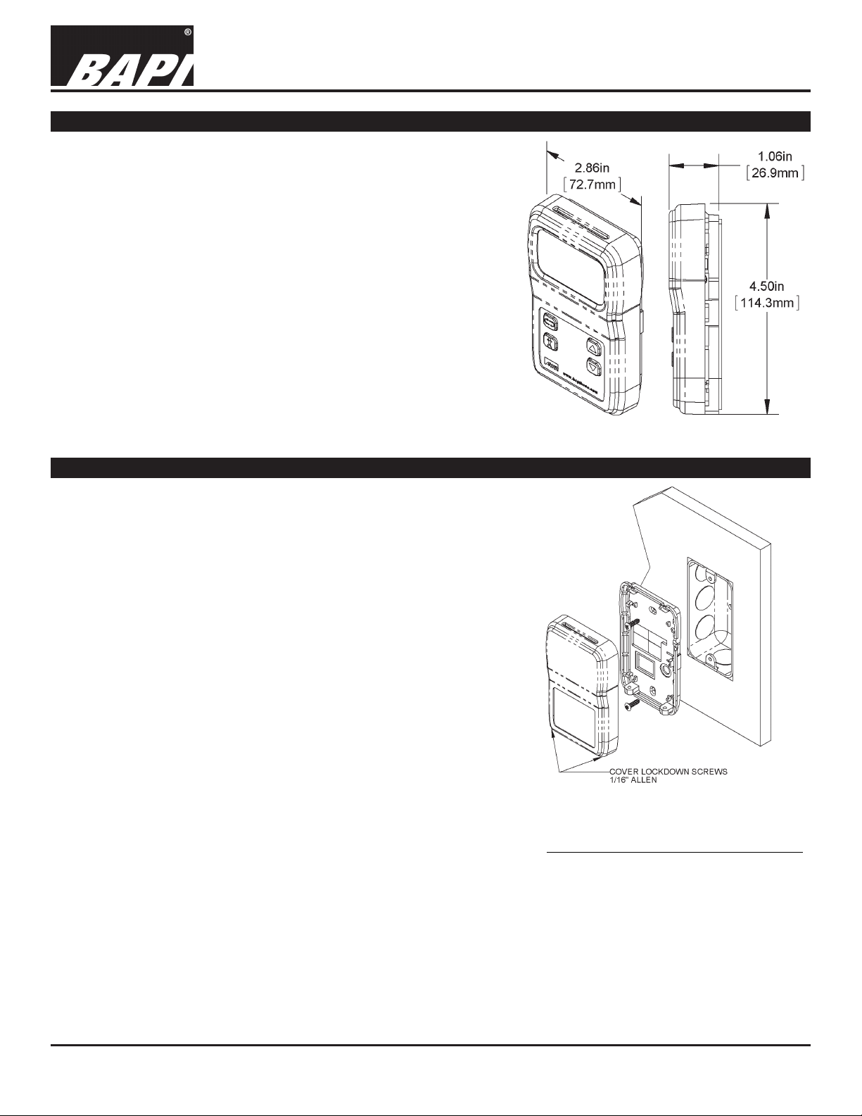
The BAPI-Stat 4MB Modbus room temperature or temperature/
humidity sensor is available with optional large-format LCD,
pushbutton setpoint, override and fan speed adjustments.
The available (and enabled) process variables are available via
standard RS485 network using an industry standard Modbus
RTU protocol.
Communications parameters and user limits are set up through
an included Page parameter adjustment system.
BAPI-Stat 4MB Modbus
unit with Display,
Setpoint and Override.
Note: Unit is also available
without display and buttons.
Installation & Operating Instructions
rev. 02/02/1834350_ins_BS4_modbus
Fig. 1:
Mounting
JUNCTION BOX
1. Pull the wire through the wall and out of the junction box, leaving
about 6 inches free. Pull the wire through the hole in the base
plate.
2. Secure the base to the box using the #6-32 x 1/2 inch mounting
screws provided.
3. Terminate the unit according to the guidelines in the Termination
section.
4. Attach Cover by latching it to the top of the base, rotating the
cover down and snapping it into place.
5. Secure the cover by backing out the lock-down screws using a
1/16” Allen wrench until they are ush with the bottom of the cover.
DRYWALL MOUNTING
1. Place the base plate against the wall where you want to mount the
sensor. Mark the two mounting holes and the area where the wires
will come through the wall.
2. Drill two 3/16” holes in the center of each marked mounting hole.
Insert a drywall anchor into each hole.
3. Drill one 1/2” hole in the middle of the marked wiring area.
4. Pull the wire through the wall and out the 1/2” hole, leaving about
Fig. 2: Mounting hardware is provided for
both junction box and drywall installation
(junction box installation shown).
6 inches free. Pull the wire through the hole in the base plate.
5. Secure the base to the drywall anchors using the #6 x 1 inch mounting screws provided.
6. Terminate the unit according to the guidelines in the Termination section.
7. Attach Cover by latching it to the top of the base, rotating the cover down and snapping it into place.
8. Secure the cover by backing out the lock-down screws using a 1/16” Allen wrench until they are ush with the
bottom of the cover.
NOTE: In a wall-mount application, the mixing of room air and air from within the wall cavity can lead to erroneous
readings, condensation, and premature failure of the sensor. To prevent this condition, plug the conduit hole with
insulation in the junction box.
Specications subject to change without notice.
1 of 7
Page 2
BAPI-Stat 4MB Modbus Temp or Temp/Humidity Sensor
Installation & Operating Instructions
rev. 02/02/1834350_ins_BS4_modbus
Termination
BAPI recommends using twisted pair of at least 22AWG and sealant lled connectors for all wire connections. Larger
gauge wire may be required for long runs. All wiring must comply with the National Electric Code (NEC) and local
codes. Do NOT run this device’s wiring in the same conduit as AC power wiring. BAPI’s tests show that uctuating and
inaccurate signal levels are possible when AC power wiring is present in the same conduit as the signal lines. If you are
experiencing any of these difculties, please contact your BAPI representative.
BAPI recommends wiring the product with power disconnected. Proper supply voltage, polarity and wiring
connections are important to a successful installation. Not observing these recommendations may damage the
product and void the warranty.
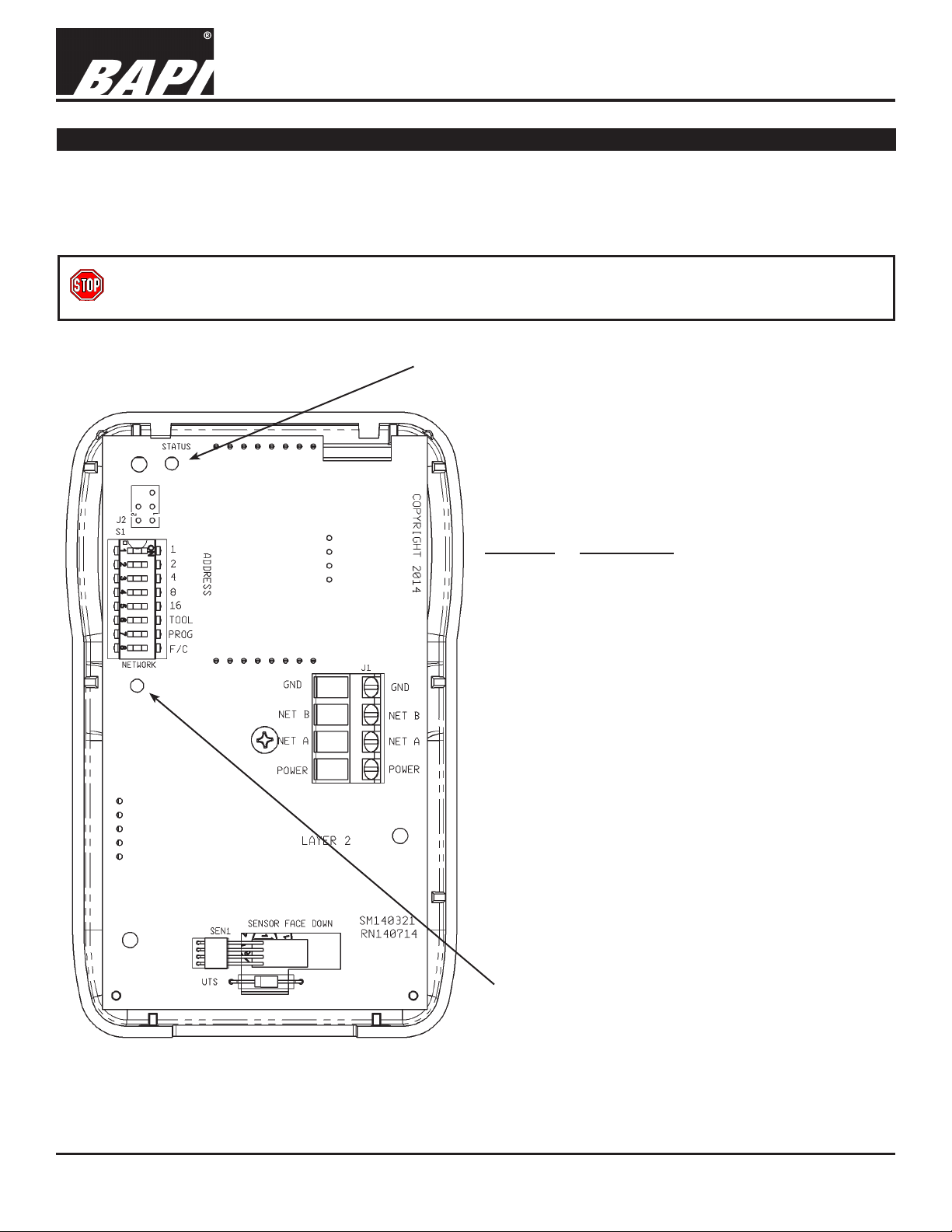
Status LED
Green - Indicates that the unit is operating propertly.
Red - Indicates that there is a problem with the unit.
Fig. 3:
BAPI-Stat 4MB Modbus
Sensor Circuit Board
Terminal Description
GND ............Power Supply Ground
(Common to the controller)
Net B...........RS485 network connection (Data -)
Net A ...........RS485 network connection (Data +)
Power .........Power Supply Hot
(See specications on page 5 for full
voltage details.)
Network LED
Flashing Red Slowly - Indicates that there has been no
communications for 60 seconds.
Flashing Green Slowly - Indicated that there have been
normal communications within the last 60 seconds.
Flashing Green Slowly with Quick Red Flashes - The
quick red ashes indicate active communications.
Specications subject to change without notice.
2 of 7
Page 3
BAPI-Stat 4MB Modbus Temp or Temp/Humidity Sensor
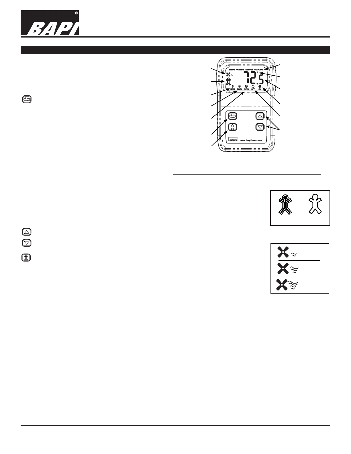
Front Panel & Control Descriptions
The BAPI-Stat 4MB is available without display and
without buttons, or with display and with four buttons Setpoint Up/Down, Scroll and Override. Fig. 4 shows
a fully featured unit. Individual LCD icons can be
controlled via specic Modbus Registers.
Scroll Button Function and Flow
The default display shows current process value
or a rotation of process values based on the Page 6
menu value. Use the Scroll button to index through
the enabled sensor parameters. (See the Register
Map on the last page for a list of allowable display
parameters.) Parameters with the “SETPOINT” icon
displayed are editable. Use the Up/Down buttons to
change them, and use the Scroll button to view the
next parameter or return to the normal display mode.
When in the Pages mode, the Scroll button becomes
the Enter button for entering a page and accepting
changes within a page.
Fan Speed
Indicator
Occupied or
Unoccupied Icon
Heat Mode
Cool Mode
Automatic
Fan Mode
Scroll Button
Override Button
Fig. 4: BAPI-Stat 4MB Modbus Unit with
Override, Setpoint and Scroll Buttons
Installation & Operating Instructions
rev. 02/02/1834350_ins_BS4_modbus
“SETPOINT” Icon
Engineering Units
Temperature Display
Fan Mode On
Fan Mode Off
Setpoint Up/Down
Buttons
BAPI-Man Icon
The BAPI-Man Icon can be used to show the zone status (see Fig. 5). The rst Modbus
write to Register 40, bit 0 (set to true) after power up will latch the BAPI-Man outline
on. Future writes or button presses will only affect the interior of the BAPI-Man. Cycling
power will reset the outline.
Up/Down Buttons
Interior On
Fig. 5: BAPI-Man Icon
Outline
The Up/Down buttons are used to adjust editable parameters whether in the Page
or Parameter/Setpoint modes.
Fan Speed
Override Button:
Low
If the Override feature is enabled then the BAPI-Man outline will be latched on and
any Override button push will do the following. An Override button press will toggle both
Fan Speed
Medium
the inner portion of the BAPI-Man icon (Fig. 5) for 10 seconds and Register 20, bit 0. This
bit and the icon are toggled again after 10 seconds. A Modbus write to Register 40, bit 0
can conrm the Override status and keep the BAPI-Man icon turned on (true) or off (false).
If the Override feature is not enabled, setting Register 40, bit 0 to true will turn on the
BAPI-Man icon, inner and outer. Setting the bit to false will clear the icon, inner and outer.
Fig. 6: Fan Speed
Fan Speed
High
Indicator
Dip Switch Options (see Fig. 7 on next page)
• Switches 1 through 5 - Sets the binary Address for the device. Units are shipped with the Address set to 1. An
Address of 0 is invalid. Additional Addresses are available using the Page 1 Menu (see pg 4).
• Switch 6 (TOOL) - Sets the unit in a Listen-Only Mode when set to On and returns the unit to Normal Operation
when set to Off. The Firmware Version and Address are displayed (on LCD units) for a short period after the
switch is set to Off.
• Switch 7 (PROG) - Sets the unit in Program Mode to access the PAGE Menus.
• Switch 8 (F/C) - Sets the display reading and the output temperature values to °F or °C.
Status and Network LEDs (see Fig. 3 on pg 2)
• Status LED - Green indicates that the unit is operating propertly. Red indicates that there is a problem with the unit.
• Network LED - Flashing Red Slowly indicates that there has been no communications for 60 seconds. Flashing Green
Slowly indicated that there have been normal communications within the last 60 seconds. Flashing Green Slowly with
Quick Red Flashes indicates active communications.
Specications subject to change without notice.
3 of 7
Page 4

BAPI-Stat 4MB Modbus Temp or Temp/Humidity Sensor
Installation & Operating Instructions
rev. 02/02/1834350_ins_BS4_modbus
Optional Technician Adjustments
The unit is shipped ready to install per the order but may require some additional setup depending on the network
and communications parameters used. The following Setup or Program Menu Changes are available if the installer
decides to change the factory settings. Note: For units without display and without pushbuttons, only Page
Menus 1, 11, 12 and 13 are adjustable, and they are accessed through Modbus communications.
ENTERING PROGRAM MODE TO ACCESS THE PAGE MENUS:
1. Remove cover and set DIP Switch #7 (PROG) to On (see Fig. 7).
2. Use the Up/Down buttons to advance to the parameter you wish to adjust.
3. Push the Scroll button to select the Page you want to view.
4. Use the Up/Down buttons to adjust the parameter
5. Push the Scroll button to select the newly adjusted parameter value.
6. To exit Program Mode, set DIP Switch #7 to Off.
QUICK VIEW PAGE MENUS:
Menu
Title Defaults
Page 1 ..........Unit Address Offset .......................................0
Page 2
Page 3
Page 4
Page 5
Page 6
...........LCD Mode .....................................................t
Page 7
Page 8
Page 9
...........Temperature Offset Adjustment .....................0.0
Page 10
Page 11
Page 12
Page 13
Page 14
..........Temperature Setpoint Low Limit ....................60°F
..........Temperature Setpoint High Limit ...................80°F
..........Humidity Setpoint Low limit ........................... 0%
..........Humidity Setpoint High Limit ......................... 100%
..........LCD Resolution .............................................0.1
..........LCD Cycle Rate ............................................5
........Humidity Offset Adjustment ........................... 0.0
........Baud ..............................................................57600
........Stop ...............................................................1
........Parity .............................................................None
........Firmware Version
Fig. 7: Dip Switches
EXPANDED PAGE MENU DEFINITIONS AND LIMITS:
Menu
Parameter Description
P1 ........Unit Address Offset: ................Selects the address offset for the unit
Allowed values are (0, 32, 64, 96, 128, 160 and 192)
Unit address is this value plus DIP switch setting.
P2 ........Temperature Setpoint Low: ....Sets the lowest value that can be set by the user.
Units (°C or °F) are selected via the DIP switch position 8
°F (-40 to 185), °C (-40 to 85)
P3 ........Temperature Setpoint High: .... Sets the highest value that can be set by the user.
Units (°C or °F) are selected via the DIP switch position 8
°F (-40 to 185), °C (-40 to 85)
P4 ........Humidity Setpoint Low: ........... Sets the lowest value that can be set by the user. (0 to 100%)
........Humidity Setpoint High: .......... Sets the highest value that can be set by the user. (0 to 100%)
P5
Continued on next page...
Specications subject to change without notice.
4 of 7
Page 5

BAPI-Stat 4MB Modbus Temp or Temp/Humidity Sensor
Installation & Operating Instructions
Optional Technician Adjustments continued...
Menu Parameter Description
........LCD Mode: .............................Sets the type of values shown on the LCD.
P6
Non – Blank LCD
t - Room temperature value only
rH - Room relative humidity value only
rHt - Room RH and room temperature value alternating
P7 ........LCD Resolution: .....................Selects the resolution for the LCD.
01 - Selects a 0.1 resolution. (xx.1).
05 - Selects a 0.5 resolution. (xx.5).
10 - Selects whole numbers for the resolution. (xx.0).
P8 .......LCD Cycle Rate: ..................... Sets the cycle time for the LCD. (3 to 10 seconds)
P9
........Temperature Offset: ................ Adjusts the measured temperature value. (-9.5° to +9.5° in 0.1° increments)
P10
......Humidity Offset: ...................... Adjusts the measured humidity value.(-9.5% to +9.5% in 0.1% increments)
P11
......Baud: ...................................... Sets the communications speed for the RS485 network.
(9600, 19200, 57600) shown as 96, 192 or 576
P12 ......Stop Bits: ................................Sets the number of stop bits required. (1 or 2)
P13
......Parity: .....................................Sets the type of parity used. (None, Odd or Even) shown as non, odd or EEn
P14
......Sensor Firmware Version: ...... Indicates the current loaded rmware in this sensor. (Readable only)
rev. 02/02/1834350_ins_BS4_modbus
General Diagnostics
POSSIBLE PROBLEM: POSSIBLE SOLUTIONS:
No Communications - Check and verify sensor address, Baud, stop bits, parity and address offset.
- Check wiring polarity
Temperature Value Incorrect - Check internal offset
Humidity Value Incorrect - Check internal offset
No Setpoints - Check enable ags
Specications
Power:
9 to 40 VDC (24 VDC nominal)
24 VAC +20%/-30%.
Note: AC power requires a separate pair
of shielded wires.
Power Consumption: 7 mA max DC;
.28 VA max AC
Sensing Element: Thermistor or Semiconductor
Wiring: See Termination Section
Terminals: 22 to 14AWG
Mounting: Standard 2 x 4” box or drywall direct
(Screws provided)
User Interface:
Setpoint
Override
............... Up & Down buttons
............... Pushbutton
Scroll.................... Display of additional
Sensor Parameters
Sensor Accuracy:
Temperature: .... ±0.2ºC from 32 to 122ºF (0 to 50°C)
%RH: ................ ±2%RH @ 25°C (77°F), 20 to 80%RH
Display: LCD, 2”W x 1.1”H Overall, 3.5 Digits@0.6”H
ICONs ............... BAPI-Man, Heat, Cool, Inside, Outside,
Auto, Off , On , Fan, Remote
Resolution ......... Whole, Half or Tenths (Process variables)
Setpoints ......... 0.5ºF, 0.1°C or 1.0% steps
Range ............... -40 to 185°F (-40 to 85°C), 0 to 100%
Setup Options:
See “Optional Technician’s Adjustments” section
Environmental Ambient:
Temperature ...... 32 to 122ºF (0 to 50ºC)
Humidity ............ 0 to 95% RH Non-condensing
Storage ............. 32 to 158°F (0 to 70°C)
Material: ABS Plastic, UL94V-0
Agency: RoHS and CE
Specications subject to change without notice.
5 of 7
Page 6

Modbus Register Allocation and Map
If flag is set then value is enabled
If flag is set then value is enabled
If flag is set then value is enabled
User Set-Point limit Low in °F 69 105 1 short xxx.xx Degrees R/W
User Set-Point limit Low in °C 6B 107 1 short xxx.xx Degrees R/W
Humidity Set-Point Limit Low 82 130 1 ushort xxx.xx Percent R/W
LCD Fan Status C1 193 1 enum R/W AUTO OFF ON FAN HIGH MED LOW Enabled
Mode Status 141 321 1 enum R/W See Details page for ENUM definitions
Network Message Counter Value 201 513 1 R
Slave Exception Counter Value 203 515 1 R
Slave Message Counter Value 204 516 1 R
Framing and Overrun Counter Value 206 518 1 R
Baud 20B 523 1 Integer (0-2) Allowed R/W 0 = 9600, 1 = 19200, 2 = 57600
Parity 20D 525 1 Integer (0,1,2) Allowed R/W 0 = none, 1 = odd, 2 = even
Register TOP F FF 4095
Reserved 1000 4096 0x1000 through 0xEFFF reserved
BAPI Modbus Register allocation and MAP Revision 01.06
Moniker, Name ID, Serial #, Revision F000 61440 16 BS4MBHn38973sMOD790126Pv01.40.01 ascii R Examp le shown
Reserved EFFF 61439 0x1000 through 0xEFFF reserved
Stop Bits 20C 524 1 Integer (1,2) Allowed R/W 1 = 1, 2 = 2
Slave NoResponse Counter Value 205 517 1 R
CRC Error Counter Value 202 514 1 R
Address Bank Offset 20A 522 1 Integer (0-6) Allowed R/W 0 = 0, 1 = 32, 2 = 64, 3 = 96, 4 = 128, 5 = 160, 6 = 192
Autotest/Reset/etc 207 519 1 Factory use only R/W
Diagnostic Flag Register 200 512 1 R
Fan Status 140 320 1 enum R/W See Details page for ENUM definitions
Humidity Set-Point Limit High 83 131 1 ush ort xxx.xx Percent R/W
LCD Mode Status C0 192 1 enum R/W OFF ON AUTO COOL HEAT Enabled
LCD Status C2 194 1 enum R/W OFF ON REMOTE OUTSIDE INSIDE Enabled
User Set-Point limit High in °C 6C 108 1 short xxx.xx Degrees R/W
User Set-Point limit High in °F 6A 106 1 short xxx.xx Degrees R/W
Temperature Set-Point COOL 63 99 1 short xxx.xx Degrees R/W If enabled this 'temperature set-point' will display in rotation du ring the 'Scroll' bu tton sequence.
Temperature Set-Point HEAT 64 100 1 sh ort xxx.xx Degrees R/W If enabled this 'temperature set-point' will display in rotation during the 'Scroll' button sequence.
Temperature Set-Point BASE 62 98 1 short xxx.xx Degrees R/W If enabled this 'temperature set-point' will display in rotation during the 'Scroll' button sequ ence.
Humidity Set-Point 81 129 1 ushort xxx.xx Percent R/W If ena bled this 'Humidity set-point' will display in rotation during the 'Scroll' button
Humidity 80 12 8 1 ushort xxx.xx Percent R/W If disabled in the PAGE mode then if enab led via flag 'humidity' will display in 'Scroll' button sequence
Digital Out Value (1) 40 64 1 Bit Flags {See bit definition} R/W RHsp LO Tsp LO OVR
Digital IN Value (1) 20 32 1 Bit Flags {See bit definition} R C or F OVR
Temperature (1) 60 96 1 short xxx.xx Degrees R/W
Mode Config 9 9 1 Bit Flags {See bit definition} R/W HCA(0) If flag is set then function/mode is enabled
Temperature config 2 2 1 Bit Flags {See bit definition} R/W RESERVED RESERVED RESERVED RESERVED Heat Cool Base RESERVED
Occupancy Config 7 7 1 Bit Flags {See bit definition} R/W OVR
Humidity Config 3 3 1 Bit Flags {See bit definition} R/W RH SP RH
Fan Config 8 8 1 Bit Flags {See bit definition} R/W FAN(3) FAN(2) FAN(1) FAN(0) If flag is set then function/mode is enabled
Device Status 1 1 1 Bit Flags {See bit definition} R Humidity Temperature If flag is set then sensor is unreliable
Device ID 0 0 1 Bit Flags {See bit definition} R Humidity Temperature If flag is set then sensor active
34350_ins_BS4_modbus
65-68 R/W No Functional use currently
61 97 1 R/W No Functional use currently
HEX DEC Size
Network Register
rev. 02/02/18
Data Format Bit 5Read/Write Bit 15 Bit 14 Bit 13 Bit 12 Bit 11 Bit 10 Bit 9 Bit 8 Bit 7 Bit 6 Bit 4 Bit 3 Bit 2 Bit 1 Bit 0
Application
UnitsName/Description
BAPI-Stat 4Modbus Temperature or Temp/Humidity Sensor
BAPI-Stat 4 Sensor with LCD and Digital Setpoints
Installation & Operating Instructions
6 of 7
Page 7

BAPI-Stat 4MB Modbus Temp or Temp/Humidity Sensor
Fan Mode
FAN(2) Fan Status Value LCD INFO
0 No FAN icon
1 FAN, 1st Wave
2 FAN, 1st and 2nd Waves
3 FAN, 1st, 2nd and 3rd Waves
FAN(3) Fan Status Value LCD INFO
0 No FAN icon
1 FAN, 1st Wave
2 FAN, 1st and 2nd Waves
3 FAN, 1st, 2nd and 3rd Waves
4 FAN, 1st, 2nd, 3rd and 4th Waves
5 FAN, 1st, 2nd, 3rd, 4th Waves and AUTO
Installation & Operating Instructions
Fan Status and Fan Display Icon Values
FAN Mode MODE mode
FAN(0) Fan Status Value LCD INFO HCA(0) Mode Status Value LCD INFO
0 FAN, 1st Wave, OFF 0 HEAT
1 FAN, 1st and 2nd Waves 1 COOL
2 FAN, 1st, 2nd and 3rd Waves 2 AUTO
3 FAN, 1st, 2nd, 3rd and 4th Waves
rev. 02/02/1834350_ins_BS4_modbus
FAN(1) Fan Status Value LCD INFO
0 FAN, 1st Wave, OFF
1 FAN, 1st and 2nd Waves
2 FAN, 1st, 2nd and 3rd Waves
3 FAN, 1st, 2nd, 3rd and 4th Waves
4 FAN, 1st, 2nd, 3rd, 4th Waves and ON
5 FAN, 1st, 2nd, 3rd, 4th Waves and AUTO
4 FAN, 1st, 2nd, 3rd and 4th Waves
Specications subject to change without notice.
7 of 7
 Loading...