

Page 1
VOC Room Sensor in the BAPI-Stat 3 Enclosure with
27018_ins_voc_room
Identication and Overview
Humans exhale Volatile Organic Compounds (VOCs) as well
as CO
therefore it is as good an indicator of space occupancy as a CO
sensor.
The BAPI Sensor is different from other VOC sensors because
it has been optimized for Demand Controlled Ventilation (DCV).
Using a calibration algorithm, the sensor value is converted to
an output with a high correlation to a CO
use ASHRAE’s occupancy-based VRP schedule to ventilate.
(More information on this correlated output is available on our
website at www.bapihvac.com)
The sensor also picks up VOCs from other sources such as
building materials, perfumes, colognes and furniture off-gassing.
Using this sensor to ventilate is a way of achieving true indoor
air quality and not just CO
The unit is available as a VOC sensor alone or in combination
with temperature and humidity. The optional display alternates
between the measured values and is eld adjustable between
°F and °C. An optional three color LED indicates a “VOC Level”
of Good, Fair or Poor.
. The BAPI sensor is able to measure these VOCs,
2
level. This lets you
2
dilution.
2
Common Ground Conguration
Installation and Operating Instructions
rev. 06/05/18
2
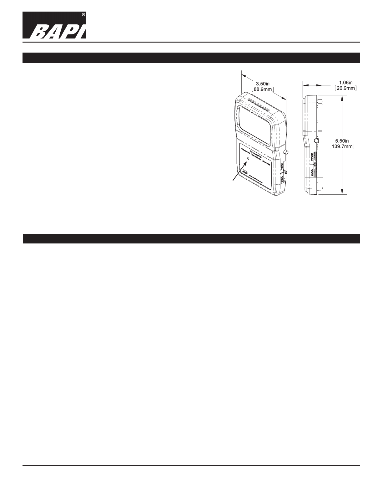
Optional
3-Color LED
Fig 1: BAPI-Stat 3 Room VOC Sensor
with Optional 3-Color LED
Specications
Power: (No AC Power)
0 to 5 VDC Output Units:
9 to 35 VDC @ 50 mA Max (9 to 15 VDC recommended)
0 to 10 VDC Output Units:
15 to 35 VDC @ 50mA Max (15 VDC recommended)
Sensing Elements:
Humidity: Capacitive Polymer, ±2% RH Accuracy
VOCs: Micro-machined Metal Oxide
Temp Sensor: Thermistor, RTD or Semiconductor
Mounting: 2”x4” J-Box or drywall mount – screws provided
VOC Detection Range: 0 to 2,000 CO2 PPM equivalent
Response Time: Less Than 60 Sec. (after Start-Up Time)
Start-Up Time: 15 minutes
Operating Environment:
32 to 122°F (0 to 50°C)
0 to 95% RH non-condensing
LCD Display:
Main Display: 0.76” 4-digit Numeric (Numeric Values)
Minor Display: 0.34” 3-digit Alpha-Numeric (PPM, %RH, °F, °C)
Occupied/Unoccupied BAPI Man Icon: (Blk=Occupied)
Note: The VOC contaminant output (CO2/VOC terminal on the circuit card) is scaled for 0 to 2,000ppm equivalent CO2
for use in an ASHRAE Standard 62.1 Demand Control Ventilation algorithm. The display shows contamination to an
equivalent 5,000ppm CO2. This allows additional troubleshooting for a building manager to determine if there is a very
large VOC contamination when the transmitted output is at its maximum value
Measurement Offsets (eld adjustable)
±5° (F or C) in 0.1° increments
±5% RH in 0.1% RH increments
±5% Contaminants in 0.1% increments
±100 ppp CO2 Equivalent Contaminants in 2 ppm incre-
ments
Analog Outputs
(0 to 5, 0 to 10 or 2 to 10VDC [%RH only], >10KΩ impedance)
VOC Contaminants: 0 to 2,000 CO2 PPM equivalent
%RH: 0 to 100% or 35 to 70% RH
Override Output:
Contact: SPST
Sensor: Shorts out direct Temperature sensor (Temp)
Setpoint: Contact in parallel, resistive setpoint only
LED CO2 Equivalent Level Indicator:
Good, Green < 1,000 PPM
Fair, Yellow = 1,000 to 1,500 PPM
Poor, Red > 1,500 PPM
Material: ABS Plastic, Material Rated UL94V-0
Certications: RoHS
Warranty Period: 5 years from manufacture date
Specications subject to change without notice.
1 of 8
Page 2
VOC Room Sensor in the BAPI-Stat 3 Enclosure with
Common Ground Conguration
Installation and Operating Instructions
27018_ins_voc_room
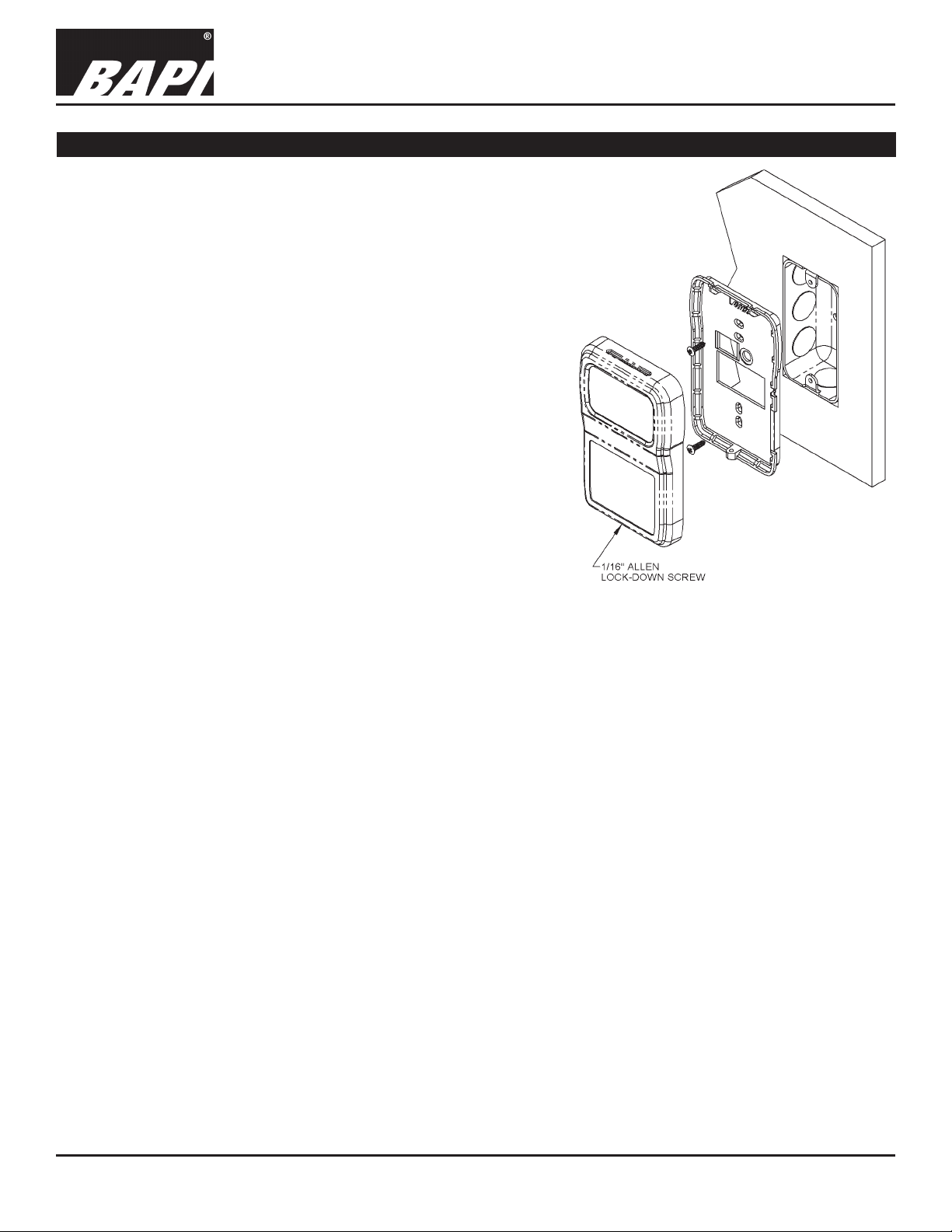
Mounting
Mounting hardware is provided for both junction box and drywall
installation (junction box installation shown).
Note: Screw the 1/16” Allen lock-down screw into the base to open the
case. There is less chance of losing the screw this way. Back out the
lock-down screw to secure the cover.
Junction Box
1. Pull the wire through the wall and out of the junction box, leaving
about six inches free.
2. Pull the wire through the hole in the base plate.
3. Secure the plate to the box using the #6-32 x 5/8 inch mounting
screws provided.
4. Terminate the unit according to the guidelines in the Termination
section. (page 3)
5. Mold the foam on the unit’s base to the wire bundle to prevent
drafts. (see note below)
6. Attach Cover by latching it to the top of the base, rotating the cover
down and snapping it into place.
7. Secure the cover by backing out the lock-down screw using a
1/16” Allen wrench until it is ush with the bottom of the cover.
Fig 2: Mounting to a Junction Box
Drywall Mounting
1. Place the base plate against the wall where you want to mount the sensor.
2. Using a pencil, mark out the two mounting holes and the area where the wires will come through the wall.
3. Drill two 3/16” holes in the center of each marked mounting hole, DO NOT punch the holes or the drywall
anchors will not hold. Insert a drywall anchor into each hole.
4. Drill one 1/2” hole in the middle of the marked wiring area.
5. Pull the wire through the wall and out of the 1/2” hole, leaving about six inches free.
6. Pull the wire through the hole in the base plate.
7. Secure the base to the drywall anchors using the #6 x 1 inch mounting screws provided.
8. Terminate the unit according to the guidelines in the Termination section. (page 3)
9. Mold the foam on the unit’s base to the wire bundle to prevent drafts. (see note below)
10. Attach cover by latching it to the top of the base, rotating the cover down and snapping it into place.
11. Secure the cover by backing out the lock-down screw using a 1/16” Allen wrench until it is ush with the bottom
of the cover.
rev. 06/05/18
NOTE: In any wall-mount application, the wall temperature and the temperature of the air within the wall cavity
can cause erroneous readings. The mixing of room air and air from within the wall cavity can lead to condensation,
erroneous readings and sensor failure. To prevent these conditions, BAPI recommends sealing the conduit leading
to the junction box, lling the junction box with berglass insulation or sealing the wall cavity.
Specications subject to change without notice.
2 of 8
Page 3
VOC Room Sensor in the BAPI-Stat 3 Enclosure with
Sensor Type Low Temp High Temp
10K-3(11K) Thermistor 7.32K (43.7°F) 3.65K (105.2°F)
Common Ground Conguration
Installation and Operating Instructions
27018_ins_voc_room
Termination
BAPI recommends using twisted pair of at least 22AWG and sealant lled connectors for all wire connections.
Larger gauge wire may be required for long runs. All wiring must comply with the National Electric Code (NEC) and
local codes.
Do NOT run this device’s wiring in the same conduit as AC power wiring of NEC class 1, NEC class 2, NEC class 3
or with wiring used to supply highly inductive loads such as motors, contactors and relays. BAPI’s tests show that
uctuating and inaccurate signal levels are possible when AC power wiring is present in the same conduit as the
signal lines. If you are experiencing any of these difculties, please contact your BAPI representative.
BAPI recommends wiring the product with power disconnected. Proper supply voltage, polarity and
wiring connections are important to a successful installation. Not observing these recommendations may
damage the product and void the warranty.
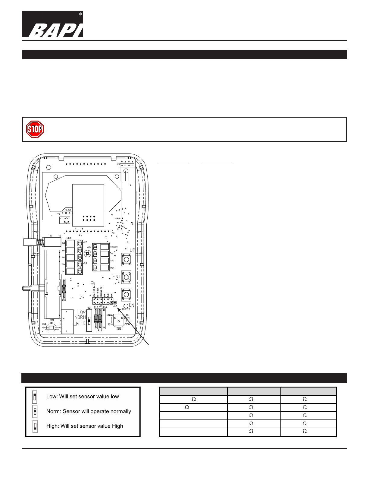
Terminal Function
OVR ..................Override Output (Dry Contact Switch). When Override
switch is pushed this terminal is connected to GND.
SET
...................Setpoint output. Referenced to ground.
...................External occupied LCD indicator is activated by logic
EXT
LOW or ground at this terminal.
TP+ & TP-
........Temperature Sensor Output (Resistive Output).
When a jumper is on J16, TP- is connected to the
GND terminal. When the jumper is off of J16, the
temperature sensor is oating.
(Semiconductor TP+ = +, TP- = -)
CO2/VOC
.........Voltage output VOC Signal (0 to 2,000 ppm)
referenced to GND
HUM
.................Voltage output Humidity Signal referenced to the GND
terminal
GND
..................To controller Ground [GND or Common]
.................Power, referenced to GND
PWR
9 to 35 VDC @ 50 mA Max
(9 to 24VDC recommended) for 0 to 5 VDC Outputs
15 to 35 VDC @ 50mA Max
(15 to 24VDC recommended) for 0 to 10 VDC Outputs
rev. 06/05/18
Note: For proper operation, the
Fig 3: Circuit Board
Optional Test and Balance Switch (SW1)
jumper on PRG connector of J19
must be connected by only one leg.
Specications subject to change without notice.
Note: Unit is not ready for
operation until the 15 minute
start-up time has elapsed.
1000 RTD 1.02K (41.2°F) 1.15K (101.5°F)
3000
Thermistor 7.87K (39.8°F) 1.50K (106.8°F)
10K-2 Thermistor 30.1K
10K-3 Thermistor 26.7K
(34.9°F) 4.75K (109.1°F)
(35.9°F) 5.11K (108.4°F)
3 of 8
Page 4

VOC Room Sensor in the BAPI-Stat 3 Enclosure with
Table 1: C35 Wiring
27018_ins_voc_room
Optional Communication Jack Wiring
Ground Black
Tip White
Ring Red
C35 Communication Jack
(Male jack shown for clarity)
User Operation
Common Ground Conguration
Installation and Operating Instructions
rev. 06/05/18
Wire Color
C35
Fig 5:
Communication Jack
BAPI Man Icon
Minor Display 0.34” 3-digit Alpha-Numeric
Main Display 0.76” 4-digit Numeric
ON Icon for
Verication and
Optional VOC Level “Arrow” Indicator
(-ARW Option)
Commissioning
Fig 6: Optional Display
The display indicates VOC in PPM, air temperature in degrees Fahrenheit or Celsius, relative humidity in %RH,
temperature setpoint in degrees Fahrenheit or Celsius and override using the BAPI Man icon. The three arrow
icons are used with the –ARW option to show VOC levels and their meaning.
The main display indicates the numeric value of the quantity being displayed. The minor display indicates the
engineering units of the value, such as VOC, °F, °C or %RH.
Temperature Setpoint Slide Pot:
Moving the slide pot enough to change the setpoint by one degree
will display the setpoint on the main display if equipped with display.
The setpoint display will hold for ve seconds after moving the slide
pot.
Override Button:
When the override button is pressed on display units, the BAPI Man
icon will display. A dry resistance of less than 1 Ohm appears from
the override output (OVR) to the Ground terminal (GND). Latching
the BAPI Man icon to show that the system is in override requires
that a dry contact on your controller be used to connect terminal
EXT to ground.
Optional VOC Level Indication via Arrow or 3-Color LED (Fig. 7)
VOC level indication is available via a black arrow on the display or
Arrow
Indicators
& Legend
LED
Indicator &
Legend
Note: Both
indicators are
not available
together
a three-color LED on the logo plate with green for good, yellow for
fair and red for poor.
Fig 7: VOC Level Indicators
Specications subject to change without notice.
4 of 8
Page 5

VOC Room Sensor in the BAPI-Stat 3 Enclosure with
Common Ground Conguration
Installation and Operating Instructions
27018_ins_voc_room
Optional Technician Adjustments
BAPI’s VOC room sensor comes calibrated and ready to operate. In some
installations the sensor may not match local instrumentation. The technician
adjustment procedure allows °F or °C display units, temperature or humidity
offsets or display information to be changed at any time, for display units only.
Removing Ground from Temperature Sensor
Some installations may experience erratic temperature readings. A
remedy may be to oat the temperature sensor as shown in Figs 8 and 9. Run
wires directly from TP+ and TP- to the controller’s analog input. The VOC/CO2
and RH jumpers are omitted for clarity.
°F or °C Display Units
Figs 10 and 11 show the jumper positions for displayed values of Celsius or
Fahrenheit degrees. The jumpers on pins PRG and BNK are omitted for clarity.
Parameter Offsets & Display Information
Figs 12 and 13 show how to place the unit into eld setup mode to adjust the
parameter offsets and display functions (shown in Table 1 below). Take the
jumper from the BNK terminals and place it on the PRG terminals. The F/C
jumper is omitted for clarity.
The major display should read P1 and the minor display should read DSP.
Use the UP/DN buttons (See Fig 14) to select the desired page.
Press and release the ENT button to select the desired page.
Use the UP/DN buttons to adjust the desired value
Press and release the ENT button to save the change and return to the page
display.
Adjust another page or place the jumper into normal operation.
possible
Fig 8: Temp.
Sensor
Grounded
Fig 10: °F
Fig 12:
Normal
Operation
rev. 06/05/18
Fig 9: Temp.
Sensor
Floating
Fig 11: °C
Fig 13:
Programming
Setup
Table 1: Parameter Offsets & Display Information
Parameter
Display Options P1 DSP
Temperature Offset P2 TMP
%RH Offset P3 %RH
VOC Offset P4 VOC
Altitude P5 ALT
Display
Main Minor
Adjustment
Item Display Action
1 Temperature Only
2 % RH Only
3 VOC Only
4 Temperature and %RH (10 second rotation)
5 Temperature and VOC (10 second rotation)
6 %RH and VOC (10 second rotation)
7 Temperature, %RH and VOC (10 sec rotation)
8 Setpoint Display Only
±5° in 0.1° increments
±5% RH in 0.1% RH increment
±100 ppm in 1 ppm increment
Effective Pressure Altitude (display only, no adjustment)
Specications subject to change without notice.
Fig 14:
Calibration
Buttons
5 of 8
Page 6

VOC Room Sensor in the BAPI-Stat 3 Enclosure with
Common Ground Conguration
Installation and Operating Instructions
27018_ins_voc_room
Output Selection
The VOC outputs may be eld congured for 0 to
5 VDC or 0 to 10 VDC outputs at any time. Set the
jumpers on J16 as shown in Figs 15 and 16. The
humidity outputs may be eld congured for 0 to 5 VDC
or 0 to 10 VDC outputs at any time. Set the jumpers on
J16 as shown in Figs 17 and 18. Note: The sensor may
be ordered with optional humidity outputs of 1 to 5 VDC
or 2 to 10 VDC, Figs 17 and 18 describe those options.
Note: The jumpers on pins not being described are
omitted for clarity.
Fig 15:
VOC Output
0 to 5 VDC
Fig 16: VOC
Output 0 to
10 VDC
Fig 17: RH
Output 0 to 5
or 1 to 5 VDC
Output 0 to 10
or 2 to 10 VDC
Sensor Start-Up
Do not set the control parameter to a VOC limit until the VOC sensor has been installed for a week. The rst few days of
install may provide different readings compared to several days later.
At each power up, the sensor enters the start-up period for 15 minutes. The main display will show the current temperature and the minor display will show 123 for the rst 15 seconds. The VOC output and display will follow the timing shown
in Fig 19. Start-up time for the humidity output is 30 seconds, while the outputs for temperature and temperature setpoint
are available immediately.
During the start-up period an optional verication/commissioning test, described below, may be performed. This test is
not mandatory, it is necessary only if building commissioning requires sensor verication or if verication of VOC output is
required for later troubleshooting.
Power ON ON Icon Illuminates ON Icon Extinguished
rev. 06/05/18
Fig 18: RH
Action
VOC Output
Voltage &
Display
Time in Minutes
0 1 2 3 4 5 6 7 8 9 10 11 12 13 14 15
VOC Sensor Acclimation
Zero
Apply
Test
Gas
5%
Dynamic Range Calculation
Undefined
Dynamic
Range
Estimate
Adapting to Environment
22.5%
Fig 19: Sensor Start-up Timeline
Optional Sensor Performance Verication and Commissioning
BAPI’s VOC sensor contains an adaptive, self adjusting, Volatile Organic Compound (VOC) sensor element that provides
a CO2 equivalent control signal output. When incorporated into a control strategy based on ASHRAE’s Demand Control
Ventilation algorithm, ventilation using this sensor will achieve true indoor air quality and not just CO2 dilution.
The fundamental performance criterion of the VOC sensor element is its dynamic sensing range. The VOC sensor element requires a minimum dynamic range of 3 for proper operation. During BAPI’s verication/commissioning test, the
dynamic range is tested and displayed.
BAPI recommends installing the sensor and powering it for at least 48 hours before the rst verication test is performed.
BAPI further recommends ventilating the space such that the sensor reads 750 ppm CO2 equivalent before any verication test is performed. Wait at least one hour before repeating the test.
1. Start Automatic Verication/Commissioning Test
A. Remove sensor power for at least one minute and reapply. The VOC sensor will set the VOC output to zero volts.
Display models will indicate 0.0 on the main display and CMS, short for commissioning, on the minor display. (Power
ON in Fig 19)
B. Wait four minutes fteen seconds.
C. The VOC sensor will set the VOC output voltage to 5% of full scale (0.25 VDC for 0 to 5 VDC, 0.5 VDC for 0 to 10
VDC or 2.4 VDC for 2 to 10 VDC outputs). Display units will illuminate the ON icon and set the main display to 1.0.
D. The visual indication and the 5% output voltage conrms that the VOC sensor is in its verication/commissioning
test. (Apply Test Gas period in Fig 19)
Continued on next page...
Specications subject to change without notice.
Normal Operation
Normal Operation
6 of 8
Page 7

VOC Room Sensor in the BAPI-Stat 3 Enclosure with
Common Ground Conguration
Installation and Operating Instructions
27018_ins_voc_room
Optional Sensor Performance Verication and Commissioning continued...
2. Apply Verication Stimulus
A. Apply the stimulus gas during the rst minute after the sensor illuminates the ON icon (See Stimulus Preparation and
Application).
B. Read and record the VOC output voltage or Main LCD display approximately 2 to 4 minutes following the stimulus
gas application to determine the dynamic range measurement. (Dynamic Range Estimate period in gure 19)
C. When the dynamic range estimate period is complete the ON icon will be extinguished.
3. Termination of Verication Mode
A. For the last 7 minutes of the start-up period the sensor adapts to its ambient environment. The VOC sensor will
maintain its output voltage at 450 ppm CO2 equivalent. Display units will show 450 ppm equivalents.
B. At 15 minutes the VOC sensor will terminate the start-up period and begin normal operation.
C. The VOC output will now report the VOCs present as CO2 equivalents.
4. Result Analysis and Recommendations
A. The VOC algorithm requires a dynamic range of greater than 30% for proper operation. Sensors reporting dynamic
range of 30% or less should be considered for replacement. (See Fig 21)
rev. 06/05/18
Stimulus Preparation and Application
Place 50ml of 70% minimum Isopropyl Alcohol (customer supplied) into a 200ml glass bottle (2oz in an 8oz glass bottle)
with stopper and allow to reach room temperature (65° to 80°F, 18° to 27°C), a minimum of 15 minutes.
1. Using a medical grade syringe, remove the stopper from the alcohol bottle, place the tip of the syringe at least half-way
into the bottle and withdraw a 60 ml sample of the ALCOHOL VAPOR. (NO LIQUID)
2. Replace the stopper on the alcohol bottle.
3. Place the end of the syringe -
A. Over, or into the top ventilation slot of the VOC monitor’s housing for room versions.
B. Into a knockout opening or
directly into the aspiration probe’s
top hole for duct mount versions.
4. Empty the syringe into the sensor
using one continuous motion.
Fig 20: Alcohol Bottle
and Syringe
Fig 21: Acceptable Dynamic Range Output
Specications subject to change without notice.
7 of 8
Page 8

27018_ins_voc_room
Diagnostics
VOC Room Sensor in the BAPI-Stat 3 Enclosure with
Common Ground Conguration
Installation and Operating Instructions
rev. 06/05/18
POSSIBLE PROBLEMS:
General troubleshooting
Incorrect VOC
Incorrect Humidity
POSSIBLE SOLUTIONS:
Determine that the input is set up correctly in the controller’s and building automation
software.
Check wiring at the sensor and controller for proper connections.
Check for corrosion at either the controller or the sensor. Clean off the corrosion, re-strip the
interconnecting wire and reapply the connection. In extreme cases, replace the controller,
interconnecting wire and/or sensor.
Label the terminals that the interconnecting wires are connected to at the sensor end and the
controller end. Disconnect the interconnecting wires from the controller and the sensor. With
the interconnecting wires separated at both ends measure the resistance from wire-to-wire
with a multimeter. The meter should read greater than 10 Meg-ohms, open or OL depending
on the meter you have. Short the interconnecting wires together at one end. Go to the other
end and measure the resistance from wire-to-wire with a multimeter. The meter should read
less than 10 ohms (22 gauge or larger, 250 feet or less). If either test fails, replace the wire.
Check power supply/controller voltage supply
Disconnect sensor and check power wires for proper voltage (see specs on pg 1)
Wait 15 minutes after a power interruption.
Check all software parameters
Determine if the sensor is exposed to an external environment different from the room
(conduit draft)
Check all software parameters
If available, check the sensor against a calibrated instrument such as a hygrometer
Determine if the sensor is exposed to an external environment different from the room
(conduit draft)
Incorrect Temperature
Determine that the temperature sensor’s wires are connected to the correct controller input
terminals and are not loose.
Check the wires at the sensor and controller for proper connections.
Make sure that the sensor leads are not touching one another.
Determine if the sensor is exposed to an external environment different from the room
(conduit or wall cavity draft)
Compare the actual temperature of the room to the resistance of the temperature sensor
inside the VOC unit. Measure the physical temperature at the temperature sensor’s location
using an accurate temperature standard. Disconnect the temperature sensor wires (Terminals
TP+ & TP-) inside the VOC unit and measure the temperature sensor’s resistance across the
sensor output pins with an ohmmeter. Put the ohmmeters black lead on Terminal TP- and the
red lead on Terminal TP+. Compare the temperature sensor’s resistance to the appropriate
temperature sensor table on the BAPI website (See below). If the measured resistance
differs from the temperature table by more than 5%, call BAPI technical support. Don’t forget
to reconnect the wires.
How to Find Temperature Sensor Resistance
Find BAPI’s web site at www.bapihvac.com; click on “Resource Library” and “Sensor Specs”,
then click on the sensor type you have.
Specications subject to change without notice.
8 of 8
 Loading...