

Page 1
13682_ins_bs_rm_unit
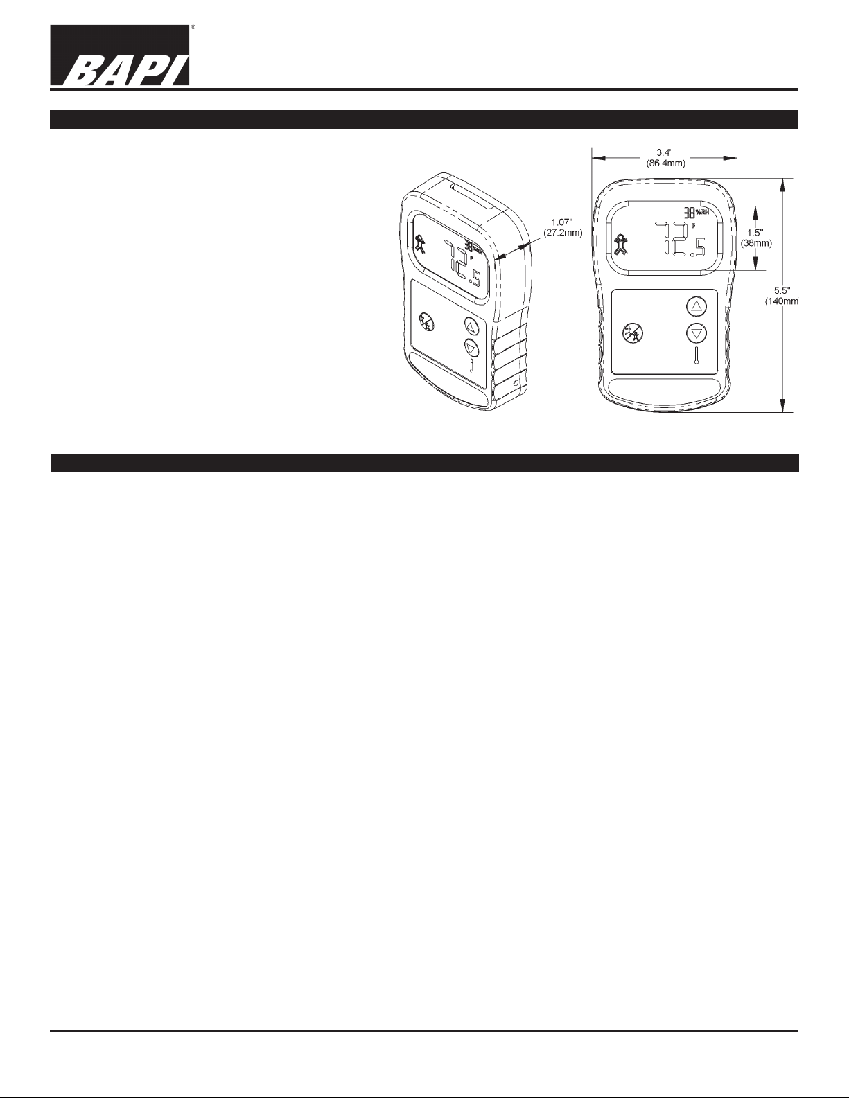
Overview and Identication
The BAPI-Stat is a multiple output transmitter for
temperature and humidity with setpoint capability
for both and occupied/unoccupied override
switching.
The large easy-to-read display is ideal for cross
room viewing and membrane push buttons are
designed for easy operation and cleaning.
A fully featured unit can have 4 active channel
outputs, override and a passive sensor output. All
ranges are factory set, however each temperature
and humidity sensor channel has a local offset
adjust for ne tuning. The display can be locally
customized to the customer’s preference.
“BAPI-Stat” – 3 Button Room Unit
Installation & Operating Instructions
rev.01/07/16
Fig. 1: 3 Button BAPI-Stat
Specications
Power Supply:
10 to 35 VDC (15 to 24 VDC Recommended) for 4 to 20 mA or 0 to 5 VDC Outputs
15 to 35 VDC (15 to 24 VDC Recommended) for 0 to 10 VDC Outputs
12 to 28 VAC (Requires a separate pair of shielded wires) for 0 to 5 VDC Outputs
15 to 28 VAC (Requires a separate pair of shielded wires) 0 to 10 VDC Output
Power Consumption:
60 mA maximum DC: 4 to 20 mA or 0 to 5 VDC Outputs
10 mA maximum DC: 0 to 10 VDC Output
1.44 VA maximum AC: 0 to 5 VDC Outputs
0.2 VA maximum AC: AC: 0 to 10 VDC Output
Outputs: 4 active output channels plus 1 passive temp. sensor
Volts 0 to 5 VDC or 0 to 10VDC, Imp. >10KΩ (CH 1, 2, 3, 4)
Current 0, 4-20 mA, Imp. <500 W @ 24 VDC (CH 1, 2)
Resistance E-POT, 1K, 10K, 50K or 100KΩ, 5 VDC @ 5 mA max (CH 3, 4) - Factory selected per application
Contact N.O. reed switch, 250 mA @ 29 V max
Temp. Sensor Passive RTD, thermistor or semi-conductor (CH 5)
Sensing Elements: Active output and display
Temperature 10K-2 Thermistor,
Humidity Capacitive Polymer, ±2%RH
Optional Passive Temperature Sensors:
Thermistor:
Temp. Output Resistance, NTC
Accuracy (std) ±0.36ºF, (±0.2ºC)
RTD: Resistance Temperature Device
Temp. Output Resistance, PTC
PT Accuracy (std) 0.12% @Ref, or ±0.55ºF, (±0.3ºC)
Semiconductor: Solid State (AD592)
Temp. Output 2 wire, 1uA/ºC (0.556uA/ºF)
Accuracy Offset correction given to 0.1ºC (0.18ºF)
Mounting:
2” by 4” J-box or drywall mount - screws provided
Thermal resistor
Controls: (Buttons required for technician adjustments)
0, 3 or 5 wipe down buttons
(Conguration dependent)
Display: LCD multi-segment
Main 3.5 digit, 0.8” tall
Minor 2.5 digit, 0.25” tall
Other BAPI-Man, units
Ambient Specications:
Temperature: 32 to 122ºF (0 to 50ºC)
Humidity: 0 to 95%, non-condensing
Wiring:
2 to 5 pair of 16 to 22 AWG
(Conguration dependent)
Material: ABS Plastic
Material Rating: UL 94, V-0
Specications subject to change without notice.
1 of 6
Page 2
“BAPI-Stat” – 3 Button Room Unit
Installation & Operating Instructions
13682_ins_bs_rm_unit
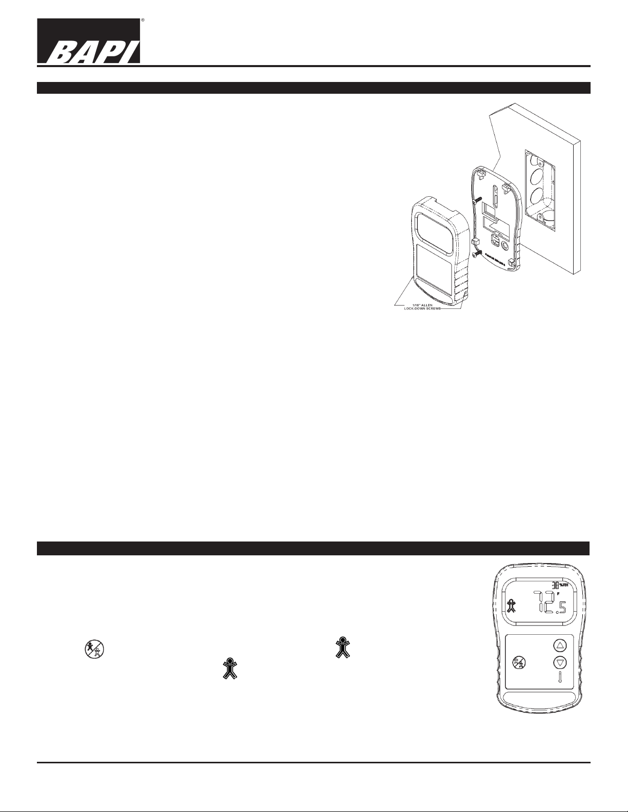
Mounting
JUNCTION BOX
1. Pull the wire through the wall and out of the junction box, leaving
about 6” free.
2. Pull the wire through the hole in the base plate.
3. Secure the backplate to the box using the #6-32 x 1/2 inch mounting
screw provided.
4. Terminate the unit according to the guidelines in the Termination
section.
5. Attach Cover by latching it to the top of the base, rotating the cover
down and snapping it into place.
6. Secure the cover by backing out the lock-down screws using a 1/16”
allen wrench until they are ush with the bottom of the cover.
DRYWALL MOUNTING
1. Place the base plate against the wall where you want to mount the
sensor.
2. Using a pencil, mark out the two mounting holes and the area where
the wires will come through the wall.
3. Drill two 3/16” holes in the center of each marked mounting hole.
Insert a drywall anchor into each hole.
Mounting hardware is provided for both
junction box and drywall installation
(junction box installation shown).
Fig. 2:
4. Drill one 1/2” hole in the middle of the marked wiring area. Pull the
wire through the wall and out the 1/2” hole, leaving about 6” free. Pull the wire through the hole in the base plate.
5. Secure the base to the drywall anchors using the #6 x 1” mounting screws provided.
6. Terminate the unit according to the guidelines in the Termination section.
7. Attach cover by latching it to the top of the base, rotating the cover down and snapping it into place.
8. Secure the cover by backing out the lock-down screws using a 1/16” allen wrench until they are ush with the sides of
the cover.
rev.01/07/16
Note: In any wall-mount application, the wall temperature and the temperature of the air within the wall cavity can cause
erroneous readings. The mixing of room air and air from within the wall cavity can lead to condensation, erroneous
readings and sensor failure. To prevent these conditions, BAPI recommends sealing the conduit leading to the junction
box with berglass insulation.
Front Panel Description
When the s or t buttons are pressed, the temperature setpoint will display, then as the buttons
are pressed again the display will change in one degree increments with each press.
Pressing and holding either button will auto increment/decrement the setpoint value.
The setpoint will change only within the specied range (as ordered).
When the button is pressed, the Occupied/Unoccupied Icon will show for a few seconds.
To retain the Occupied/Unoccupied Icon , you must energize J6*.
(*For more information on Occupied/Unoccupied Icon, see the “Termination” and the “Display
Occupancy Mode Termination” sections)
Fig. 3:
Front View of BAPI-Stat
Specications subject to change without notice.
2 of 6
Page 3

“BAPI-Stat” – 3 Button Room Unit
Installation & Operating Instructions
13682_ins_bs_rm_unit
Termination
BAPI recommends using twisted pair of at least 22 AWG. Larger gauge wire may be required for long runs. All wiring
must comply with the National Electric Code (NEC) and local codes. Do NOT run this device’s wiring in the same conduit
as AC power wiring of NEC class 1, NEC class 2, NEC class 3 or with wiring used to supply highly inductive loads such
as motors, contactors and relays. BAPI’s tests show that uctuating and inaccurate signal levels are possible when AC
power wiring is present in the same conduit as the signal lines.
BAPI recommends wiring the product with power disconnected. Proper supply voltage, polarity, and wiring
connections are important to a successful installation. Not observing these recommendations may damage the
product and will void the warranty.
Terminal Notes: (Related to table 1), [ ] = Terminal designation
1. Only one variable and output type per channel. [CH3] and [CH4] can be
overridden.
2. The [GND] terminal is always the reference for [V+], [CH1] and [CH2]
terminals.
3. The temperature output range is limited to between 32º to 158ºF
(0º to 70ºC).
Power
Supply
Ground
Power
Supply
Hot
4. Humidity setpoint range is limited between 0 to 100% RH.
5. The override is available on [CH3], [CH4] and [TEMP+/TEMP-] only.
6. Voltage outputs are limited to between 0-10 VDC and are only
referenced to [GND].
7. Current outputs are limited to between 0-20 mA and are only referenced to
[GND].
8. Resistive E-POT outputs are limited to a 1K, 10K, 50K or 100KW linier
POT, ±30%.
9. Resistive sensor [TEMP+/TEMP-] outputs may be any BAPI passive or
solid state sensor.
10. When using a 592/334 sensor, [TEMP+] is the supply (5 to 30 VDC)
[TEMP-] is the current output to the analog input @ 1µA/ºC and requires
S1-4 to be set for (DF). Reversal of the power will damage the sensor.
11.
The Test and Balance option (-TB) cannot be used with the 592/334 sensor.
12. If the BAPI-Stat has the external sensor option (-EXT), then it must be a
10K-2 thermistor purchased separately. The external sensor is wired to the
Fig. 4: BAPI-Stat Circuit Board
temp + and temp - terminals. A humidity signal or passive sensor are not
allowed in this conguration.
rev.01/07/16
Table 1: TerminationTable
Input Power
Terminal
Name
GND Pwr- & Sig- Sig- Sig- * **, ^ ** ***
V+ See spec’s
CH1 CG X X X Sig+ mA +
CH2 CG X X X Sig+ mA+
CH3 CG/DF* per order X X ^^E-POT Sig+ ^^*<100KΩ *E-POT
CH4 CG/DF* per order X X
TEMP+ Sensor ^^^N.O ~ ~ N.O. Sensor V+
TEMP- CG/DF, S1-4** Sensor ^^^N.O. ~ ~ **N.O. Sensor ***V-
* [CH3] and [CH4] are referenced to [GND] if (CG) is selected at time of order. [CH3] and [CH4] are referenced to each other if (DF) is selected at time of order.
** S1-4, Position (CG) connects [Temp-] terminal to the [GND] terminal internally. The (DF) position makes the [TEMP -] terminal oating. (See Fig.10)
*** This is the current output of the solid state sensor and must be congured as S1-4 set to (DF) to allow the 592 or 334 sensor to operate.
^ The reed contact to override [CH4] can be set up for (CG) which shorts the [CH4] output to [GND] or (DF) shorting the output terminals [CH3/CH4].
^^ The E-POT controls the output resistance setpoint and during override, the E-POT controls the resistance to <100 ohms for 3-5 seconds.
^^^ A reed dry contact across the sensor [TEMP+/-] is congured at time of order as a (-61) option.
~ The [TEMP] terminals are used for an external 10K-2 thermistor connection [EXT option] for display and transmitted output (wire=25’ max).
Supply
Power
Internal
Grounding
CG=Com. GND
DF=Isolated
Output Variable (See your unit label for your conguration) Output Signal (See your unit label for your conguration)
Temperature
Output
Humidity
Output
Temperature
Setpoint
Output
Humidity
Setpoint
Output
Override
Output
^^E-POT/^N.O. Sig+
Voltage
Output
Current
Resistive
Output
^^*<100KΩ *E-POT/^N.O.
Output
Signal Override
Contact
Passive
RTD or
Thermistor
Sensor
592/334
Solid
State
Sensor
3 of 6
Page 4

“BAPI-Stat” – 3 Button Room Unit
Resistance Value
Resistance Value
1000Ω RTD 1.02KΩ (41.20°F) 1.15KΩ (101.5°F)
3000Ω Thermistor 7.87KΩ (39.8°F) 1.5KΩ (106.8°F)
10K-2 Thermistor 30.1KΩ (34.9°F) 4.75Ω (109.1°F)
10K-3 Thermistor 26.7KΩ (35.9°F) 5.11KΩ (108.4°F)
13682_ins_bs_rm_unit
Display Occupancy Termination Mode (Remote Control)
When the override button is pushed, the override output is active for 3
to 5 seconds. Simultaneously, the outline and center of the Occupied/
Unoccupied Icon on the display will be lled in for 3 to 5 seconds and
then go blank.
If you need visual indication of the override on the LCD display, the
controller must have a digital output connected to the sensor’s threepin EXT OVR terminal block, J6.
When appropriate power is connected between the EXT OVR common
and either 5 VDC or 24 VDC/VAC, both
the outline and center of the Occupied/
Unoccupied Icon will be lled in. When the external override is canceled, the Occupied/
Unoccupied Icon’s outline will remain lled in to show that the external override was used.
Occupied
Icon Filled In
Unoccupied
Icon Outline
If power to the sensor is removed, the outline will be blank until the next time the external
override is used. This input is optically isolated from the rest of the device’s circuitry.
Installation & Operating Instructions
rev.01/07/16
Terminal
Name
COMMON
5VDC
24V DC/VAC
Table 2: Override Display Termination Table
This [COMMON] is isolated from the other [GND]
terminal. See Figures 5 & 6 for more details.
ICON ON
5VDC
-
+
ICON ON
24VDC
- ~N
+
ICON ON
24VAC
~H
Controller Output OPEN
=
Fig. 5: 5VDC Wiring Example
Controller
Digital
EXT OVR Display Input
Optional Communication Jack Wiring
Optional Communication Jack Termination Wiring
Fig. 7: C11 Jack
Fig. 8: C35 Jack
Note: Male Jack shown for clarity
Specications subject to change without notice.
Output
5VDC Customer
Power Supply
Table: 3 C11/22 Wiring
Comm Jack Pin Wire Color
1 Not Connected
2 Black
3 Red
4 Yellow
5 White or Green
6 Not Connected
Table: 4 C35 Female Jack Wiring
Comm Jack Pin Wire Color
Ground White
Tip Black
Ring Red
Controller Output CLOSED (Override) =
Fig. 6: 24VDC/VAC Wiring Example
EXT OVR Display Input
Fig. 9:
View of
BAPI-Stat
wallplate
Controller
Digital
Output
24DC/AC
Customer
Power Supply
Test & Balance Switch (-TB), (For Passive Sensor Ouput Only)
Optional Test and Balance Switch (SW1)
(Output at Temp+ and Temp- Terminals)
Low: Will set the sensor value low
Norm: Thermistor/RTD will operate normally
High: Will set the sensor value high
Consult Factory for Additional Details
Specications subject to change without notice.
Sensor Type
Low Temp (40° F)
High Temp (105°F)
10K-3(11K) Thermistor 7.32KΩ (43.7°F) 3.65Ω (105.2°F)
4 of 6
Page 5

“BAPI-Stat” – 3 Button Room Unit
Installation & Operating Instructions
13682_ins_bs_rm_unit
Optional Technician Adjustments
The four DIP switches on the bottom of the board called S1 congure four different parameters (see Fig: 10).
1) Fahrenheit or Celsius temperature display “F/C” Switch.
2) Display Reading Offset “Mode” Switch for temperature and humidity appearance and output offset.
3) User Setpoint Lockout Enable “SPLO” Switch.
4) Passive temperature sensor differential ground or common ground conguration “TEMP” Switch.
ADJUSTMENT PROCEDURE FOR EACH DIP SWITCH IN S1:
°F OR °C DISPLAY SELECTION [F/C Switch]
The “F/C” Switch allows for either °F or °C operation. Remove the cover from the
backplate and set the switch to the desired position.
DISPLAY READING OFFSET [MODE Switch] (3 button sensor required)
The Display Reading Offset “Mode” Switch lets you adjust the reading of the BAPIStat display. For example if the display reads 70° but you wish it to display and
send a signal to your controller of 70.5°, you will enter an adjustment of 0.5. If the
display reads 40 %RH and you wish it to display and send a signal to your controller of 38% RH, you will enter -2.0.
1) Remove cover from backplate & slide the “MODE” switch on S1 to the “OFFSET” position.
The screen in gure 11 will appear on the display. If you previously entered an offset, the offset
you entered will show on the display. Either the F or C annunciator will be lit depending on the
position of “F/C” Switch
2) Press the Override button on the front of the sensor to advance to the screen for the parameter
you wish to change.
a. TEMPERATURE OFFSET - Screen P26 (gure 11)
b. HUMIDITY OFFSET - Screen P27 (gure 12)
c. DISPLAY MODE - Screen P28 (gure 13)
d. ACTIVE TEST & BALANCE MODE - Screen P29 (gures 14 & 15)
3) Use the Temperature Setpoint up and down arrows on the front of the sensor to select the
calibration needed.
a. TEMPERATURE OFFSET - Adjust the temperature ± 5°in 0.1° increments
b. HUMIDITY OFFSET - Adjust the humidity ± 5% in 0.1% increments
c. DISPLAY MODE - Adjust to 0 through 7 depending on the display mode you desire.
0 - Temperature in the main portion and %RH in the upper section
1 - %RH in the main portion and Temperature in the upper section
2 - The LCD toggles the locations at a ~5 second rate
3 - Temperature Only.
4 - Setpoint Display Only (SDO), Temp Setpoint in the main portion and %RH Setpoint in
the upper section
5 - Setpoint Display Only (SDO), %RH Setpoint in the main portion and Temp Setpoint in
the upper section
6 - Setpoint Display Only (SDO), The LCD toggles the setpoints between the locations at a
~5 second rate
7 - Setpoint Display Only (SDO), Temperature Setpoint only.
(Note: Selecting options 1, 2, 5 or 6 with units without %RH will default to mode 0)
d. ACTIVE TEST & BALANCE MODE - Setpoint buttons up or down toggles between ‘LO’
and ‘HI’ on the LCD. This mode is active only for models which use Channel 1 as a
temperature output. ‘LO’ will drive Channel 1 to it’s lowest voltage or current output. ‘HI’
will drive Channel 1 to it’s highest voltage or current output. (gures 14 & 15)
4) Press the Override button on the front of the sensor to ‘enter’ and store the change. Set the
“MODE” switch on S1 back to “RUN” and put the cover on the backplate.
Fig. 10: Conguration Switches S1
Fig. 11: Temp Offset
Fig. 12: %RH Offset
Fig. 13: Display Mode
Fig. 14: T&B Mode Lo
rev.01/07/16
SETPOINT LOCK OUT [SPLO Switch]
The “SPLO” Switch allows the setpoint buttons to be disabled. A switch setting of “ON” disables the
buttons.
PASSIVE TEMPERATURE SENSOR GROUNDING [TEMP switch]
Adjust DIP switch to “CG” for [TEMP –] connected to common ground [GND]
Adjust DIP switch to “DF” for [TEMP –] differential oating without connection to any ground.
Fig. 15: T&B Mode Hi
5 of 6
Page 6

13682_ins_bs_rm_unit
Diagnostics
“BAPI-Stat” – 3 Button Room Unit
Installation & Operating Instructions
rev.01/07/16
POSSIBLE PROBLEMS
General Diagnostics
Unit does not operate
POSSIBLE SOLUTIONS:
- Determine that the input is set up correctly in the controller’s and building automation
software.
- Check wiring for proper termination
- Check for corrosion at either the controller or the sensor. Clean off the corrosion, restrip the interconnecting wire and reapply the connection. In extreme cases, replace the
controller, interconnecting wire and/or sensor.
- Label the terminals that the interconnecting wires are connected to at the sensor end
and the controller end. Disconnect the interconnecting wires from the controller and the
sensor. With the interconnecting wires separated at both ends measure the resistance
from wire-to-wire with a multimeter. The meter should read greater than 10 Meg-ohms,
open or OL depending on the meter you have. Short the interconnecting wires together
at one end. Go to the other end and measure the resistance from wire-to-wire with a
multimeter. The meter should read less than 10 ohms (22 gauge or larger, 250 feet or
less). If either test fails, replace the wire.
- Check power for proper polarity.
- Disconnect the power wires at the controller. Measure controller output for proper
power (see specications), if the voltage is outside the limits trouble shoot controller.
Reconnect power wires to controller when nished. If the measured voltage is above
the specication limit, you may have damaged the BAPI-Stat, contact your BAPI
representative.
- Disconnect the power wires at the sensor. Measure the wires for the same voltage as
at controller. If the voltage is different from that measured at the controller troubleshoot
wire. Reconnect power wires to sensor when nished.
- Measure the power at the sensor with the power connected for proper power
(see specications), if the voltage is outside the specication limits call your BAPI
representative.
If you need more help troubleshooting a BAPI-Stat problem, see the advanced troubleshooting guide on the BAPI-Stat
sensor page on our website at http://www.bapihvac.com
Specications subject to change without notice.
6 of 6
 Loading...