

Page 1
BAPI-Slim™ Wireless Temperature Transmitter
28936_ins_WFC
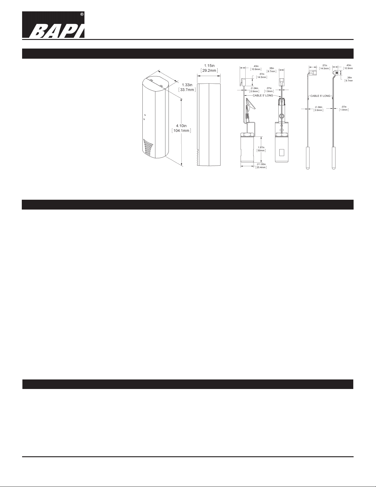
Identication and Overview
The BAPI-Slim Wireless Temperature
Transmitter is designed to monitor
temperature inside refrigerator and
freezer cases. The BAPI-Slim mounts
on the outside of freezer units and
can be mounted either inside or
outside of refrigerator units. The unit
is available with an internal sensor or
an RJ11 jack external sensor.
The external sensor’s ribbon cable
can easily t between the door seal
or through hole with FEP cable
without affecting appliance efciency.
The temperature is then transmitted
at 30-second intervals to the receiver
with a remote probe measurement
range of -40 to 185˚F (-40 to 85˚C).
Fig. 1: BAPI-Slim Wireless
Temperature Transmitter
(Battery Operated)
Installation and Operating Instructions
rev. 06/03/16
Fig. 2: External
Hanging Bracket
Sensor
Fig. 3:
External Probe
Sensor
Specications
Supply Power:
Activation: Starts to transmit when battery is installed (or
battery tab removed) and training button
pushed
Training: A button on the inside of the case. (Pushed
with paper clip through a pin hole in case)
LED: Transmit LED Inside Cover (Visible through
the lower pin hole in the case.)
Battery: 4 Year Replaceable, 1/2 AA, (3.6 VDC)
Battery Ambient: -67° to 185ºF (-55° to 85ºC)
Sensor: Thermistor, 10K-2
Internal: Located at Bottom of Case
External: RJ11 Jack
2” SS Sensor w/ Ribbon Cable or FEP Cable
2” Thermobuffer w/ Ribbon Cable or FEP Cable
Measurement Range: -40 to 185˚F (-40 to 85˚C)
Accuracy: ±0.5ºF (±0.28ºC) from -40 to 185ºF (-40º to 85ºC)
Environmental Operation:
Stainless Steel Probe: -40 to 185˚F (-40 to 85˚C)
Electronics: -22 to 122ºF (-30 to 50ºC)
Humidity: 0 to 95% RH Non-condensing
One 3.6 VDC Lithium Thionyl Chloride Battery
Case Material: ABS Plastic
Ext. Probe Material: 304 Stainless Steel (SS)
Transmitter Mounting:
Keyhole Screw Mounts (Screws not included)
Double-Sided Mounting Tape (Included)
Sensor Mounting:
Remote Probe: Plastic Holder (BA/FPB)
Thermobuffer: Hanging Rack Clip (Included)
Radio Frequency: 418 MHz @ 1mW
Transmitter Interval: Factory selectable from 10 sec to
10 minutes in 5 second intervals (30 seconds default)
Antenna: Spiral Type Built into Case
Transmission Range:
Up to 100 Ft Open Air (418 MHz @ 1mW)
Up to 1,000 Ft Open Air with Repeater (900MHz @ 100mW)
Warranty: 2 Years from Date of Manufacture
Agency:
RoHS
Industry Canada (IC:9067A-SM061025)
Flammability: UL 94 V-O
FCC Approval: FCC ID# T4FSM061025 (418MHz Only)
FCC Compliance
Compliance: This device complies with Part 15 Subpart B of the FCC rules Operation is subject to the following conditions.
1. This device may not cause harmful interference.
2. This device must accept any interference received, including interference that may cause undesired operation.
FCC Radio Frequency Interference Statement:
This equipment has been tested and found to comply with the limits for a Class B digital device, pursuant to Part 15,
Subpart B, of the FCC Rules. This equipment generates, uses, and can radiate radio frequency energy. If not installed
and used in accordance with the instructions, it may cause interference to radio communications.
Specications subject to change without notice.
1 of 4
Page 2
28936_ins_WFC
Mounting
BAPI-Slim™ Wireless Temperature Transmitter
Installation and Operating Instructions
rev. 06/03/16
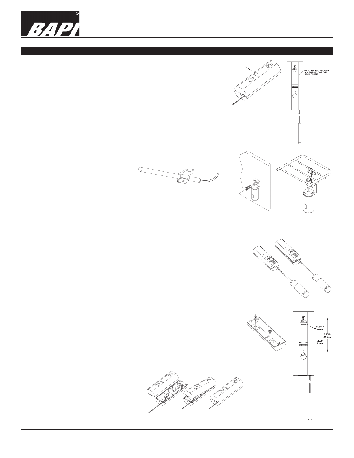
There are two ways to mount the wireless transmitter. One uses a keyhole
screw mount and the other uses double stick mounting tape. Both techniques
BATTERY
TAB
can be used together if desired.
TRANSMITTER MOUNTING WITH TAPE
1. Remove the battery tab by pulling the tab straight out to start the transmitter
(Fig. 4). The battery will last about 4 years before replacement is required.
2. Peel off one side of the mounting tape and apply the mounting tape to the
back (Fig. 5).
Fig. 4: Transmitter
Activation & Battery
3. Select a location you would like monitored or within reach of the remote
sensor. Any orientation is acceptable although vertical will enhance the
transmitter distance.
4. Peel off the mounting tape, position the sensor and rmly push it into place.
5. For units with an internal sensor the mounting process is complete.
6. For remote sensors, string the wire
through the freezer door and place
the sensor in the best location to
measure the required temperature.
7. Mount the External Probe using a
Flexible Probe Bracket (Fig. 6) or
use the clip or screw hole on the
Fig. 6: External Probe Mounting with
a Flexible Probe Bracket (BA/FPB)
Hanging Bracket Sensor (Fig. 7)
TRANSMITTER MOUNTING WITH SCREWS
1. Remove the battery tab to start the transmitter (Fig. 4). The battery will last
about 4 years before replacement is required.
2. Remove the back plate by inserting a small thin screwdriver in the bottom slot and
pushing gently. Then swing the cover up and off (Fig. 8).
3. Select a location within reach of the remote sensor. Any orientation is acceptable
although vertical mount will enhance the transmitter distance.
4. Mark the mounting holes by using the transmitter backplate as a template (Fig. 9).
Drill holes and use hardware appropriate for the application (hardware not included).
6. For units with an internal sensor, the mounting process is complete. Place the
transmitter over the back plate by hooking at the top of the back plate and swinging
down until it snaps into place (Fig. 10).
7. For remote sensors, string the wire through the freezer door and place the sensor
in the best location to measure the required temperature. Sensor removal from the
transmitter may be necessary. See Fig. 11.
8. Mount the External Probe using a Flexible Probe Bracket (Fig. 6) or use the clip or
screw hole on the Hanging Bracket Sensor (Fig. 7). Reconnect the remote sensor if
necessary (Fig. 11)
9. Place the transmitter over the back plate by hooking the transmitter at the top of
the back plate and swinging down until it snaps into place. Be sure the remote
sensor wire is lined up with the bottom slot (Fig. 10).
Tab Removal
Mounting
Application
Fig. 7: External Hanging Bracket
Sensor Mounting
FLATHEAD
SCREWDRIVER
Fig. 8:
Transmitter
Cover Removal
Fig. 9:
Mounting Hole
Location and
Mounting of
Unit
Fig. 5:
Tape
Fig. 10: Cover
Replacement
Specications subject to change without notice.
2 of 4
Page 3

BAPI-Slim™ Wireless Temperature Transmitter
Installation and Operating Instructions
28936_ins_WFC
Remote Sensor Connection
If the transmitter has an internal sensor then there is no external wiring. If a remote
sensor is used, then it is terminated using an RJ11 connector inside the transmitter case.
Remote Sensor Connection
1. Remove the back plate by inserting a small thin screwdriver in the bottom slot and
pushing gently. Then swing the cover up and off (Fig. 8).
2. An RJ11 connector is located at the bottom of the board. Insert the sensor RJ11 plug
(tab down) into the connector until it is fully seated (Fig. 11).
3. Place the transmitter over the base plate by hooking the transmitter at the top of the
back plate and swing down. Be sure the remote sensor wire is lined up in the bottom
slot and swing the cover down until it snaps into place (Fig. 10).
Battery Replacement
New transmitter installations are powered by a pre-installed battery.
To activate the unit, nd the battery tab insulator in the back of the
unit, pull it out and discard the tab (Fig. 4) and push the training
button (Fig. 14). The transmitter will start to transmit approximately
every 30 seconds.
Battery Replacement
1. Replacement requires the removal of the back plate by inserting
a small thin screw driver in the bottom slot and gently push then
swing the cover up and off (Fig. 8).
TRANSMITTER SERIAL NUMBER
(ON BATTERY HOLDER AND ON
STICKER ON BACK OF UNIT)
Fig. 11: Remote
Sensor Connection
TRAINING
BUTTON
HOLE
TRANSMIT
LED HOLE
rev. 06/03/16
2. Remove the old battery and install a new battery (BA/BAT-5AAHIT) so that the negative faces up toward the antenna (Fig. 12).
Push the training button (Fig. 14) and the transmitter will start to
transmit approximately every 30 seconds. The transmission LED
(Fig. 13) will ash once for each transmission.
3. Place the transmitter over the base plate by hooking the
transmitter at the top of the back plate and swing down. Be sure
the remote sensor wire, if used, is lined up in the bottom through
Fig. 12: Transmitter
Internal Components
slot and swing the cover down until it snaps into place (Fig. 10).
Setup and Commissioning
As soon as the batteries are installed (or the insulating battery tab is removed) and
the training button is pressed, the transmitter will start to transmit the temperature
using the serial # code shown on the battery holder (Fig. 12). A small transmit LED
on the circuit board ashes once for each transmission. This happens at 30 second
intervals. This LED is visible through the lower hole on the front cover (Fig. 13).
When using a receiver with one or more Analog Output Modules, the transmitter
will have to be trained to an individual Analog Output Module on the receiver. To do
this, push and hold the Service Button on the Analog Output Module you wish to
train. Then push and release the Training Button on the transmitter with a paper clip
through the top faceplate hole (Fig. 14). The Analog Output Module LED will light up,
indicating a successful training process. The LED on the Analog Output Module will
then ash with each received transmission, approximately every 30 seconds.
Fig. 13: Transmit
LED & Training
Button
PAPER
CLIP
TRAINING
BUTTON
HOLE
Fig. 14: Accessing the
Training Button through
the Front Cover
Specications subject to change without notice.
3 of 4
Page 4

BAPI-Slim™ Wireless Temperature Transmitter
Installation and Operating Instructions
28936_ins_WFC
Diagnostics
Possible Problems: Possible Solutions:
The unit is suspected of not transmitting - Verify that the Transmit LED (Fig. 13) on the transmitter ashes at 30
second intervals. If the LED is not ashing, press the Training Button
(Fig. 14) and recheck if the transmit LED is ashing.
Unit is not talking to the analog output module - If this is a 900MHz system (has a repeater), then be sure the repeater is
within range of the transmitter and within range of the receiver.
- Re-train the analog output module as described in the “Setup and Commissioning” section.
Sensor reads low - Remove the sensor from the case by unplugging the RJ11 plug.
Measure the resistance of the two center terminals and compare
this resistance to the resistance found on the resistance/temperature
chart for the 10K-2 thermistor on the BAPI website. If the measured
resistance is different from the temperature table by more than 5%,
call BAPI technical support. Find BAPI’s website at www.bapihvac.
com; click on “Resource Library” and “Sensor Specs”, then click on the
10K-2 Thermistor sensor.
rev. 06/03/16
Battery may be low - Check the battery voltage to see that it is 2.6 volts or greater. If it is less
than 2.6 volts, replace the battery. The batteries should last for 4 years.
Related Products
Part Number Description
BA/RCV418-WAM-x-EZ ....Wireless 418MHz Wireless Asset Monitoring (WAM) Receiver
BA/RCV418-EZ .................418MHz Wireless Receiver for Analog Output Modules
BA/RCV900-EA-EZ ...........900MHz Wireless Receiver for Analog Output Modules (requires a repeater)
BA/RPT49-EA-EZ .............. 418 MHz to 900MHz Repeater
BA/VOM-10-x-EZ ............... 0 to 10V Voltage Output Module
BA/COM-x-EZ .................... 4 to 20mA Current Output Module
BA/ROM-10x-EZ ................ Resistance Output Module, 10K-2 Thermistor Output
BA/BAT-5AA-HIT .............. Replacement Battery, ½ AA, 3.6V
Specications subject to change without notice.
4 of 4
 Loading...