

Page 1
Wallplate with Semiconductor Sensor (BA/592-SP/AP)
10KΩ uncertainty Table
Tolerance
Temperature uncertainty
0.1%
±8.64°F
1%
±13.47°F
5%
±34.93°F
Table 2: 592 2-Wire Sensors
Table 3: 592 3-Wire Sensors
1. Install a 10KΩ 0.1% resistor from the controller's
analog input to the controller's ground or common.
1. All BAPI BA/592-10K, 3-wire, sensors have a built
in 10KΩ 0.1% resistor.
2. If you are using a separate DC power supply,
connect the power supply's negative terminal to the
controller's ground or common..
2. If you are using a separate DC power supply,
connect the power supply's negative terminal to the
controller's ground or common..
3. Connect the 592 sensor's black wire to the
controller's analog input.
3. Connect the 592 sensor's black wire to the
controller's ground or common.
4. Connect the 592 sensor's red wire to 5 to 30
VDC.
4. Connect the 592 sensor's white wire to the
controller's analog input.
5. Connect the 592 sensor's red wire to 5 to 30
VDC.
Installation & Operating Instructions
16558_ins_592_SP_AP
592 Theory of Operation
The 592 Semiconductor sensor is a two terminal integrated-circuit temperature sensor. The 592 provides an output
current directly proportional to absolute temperature. When the temperature of the 592 sensor changes one-Kelvin (onedegree Celsius), then the current through the 592 changes by 1uAmp. 77° Fahrenheit (25° Celsius) is 298.2 Kelvins and
the output current from the 592 sensor is 298.2uAmp. Initial accuracy of the 592 temperature sensor is ± 8.1° Fahrenheit
(± 4.5° Celsius) at 77° Fahrenheit (25° Celsius).
Since most meters that eld technicians use cannot accurately measure currents this low, BAPI recommends that a 10KΩ
0.1% resistor be placed between the sensor output and ground. The 10KΩ resistor changes the current into a voltage
that varies 0.01 volts per one degree Celsius temperature change; the
voltage at 77°F is 2.982 VDC. Resistors with other tolerances can be
used, but you will have greater temperature uncertainty, see the 10KΩ
uncertainty table;
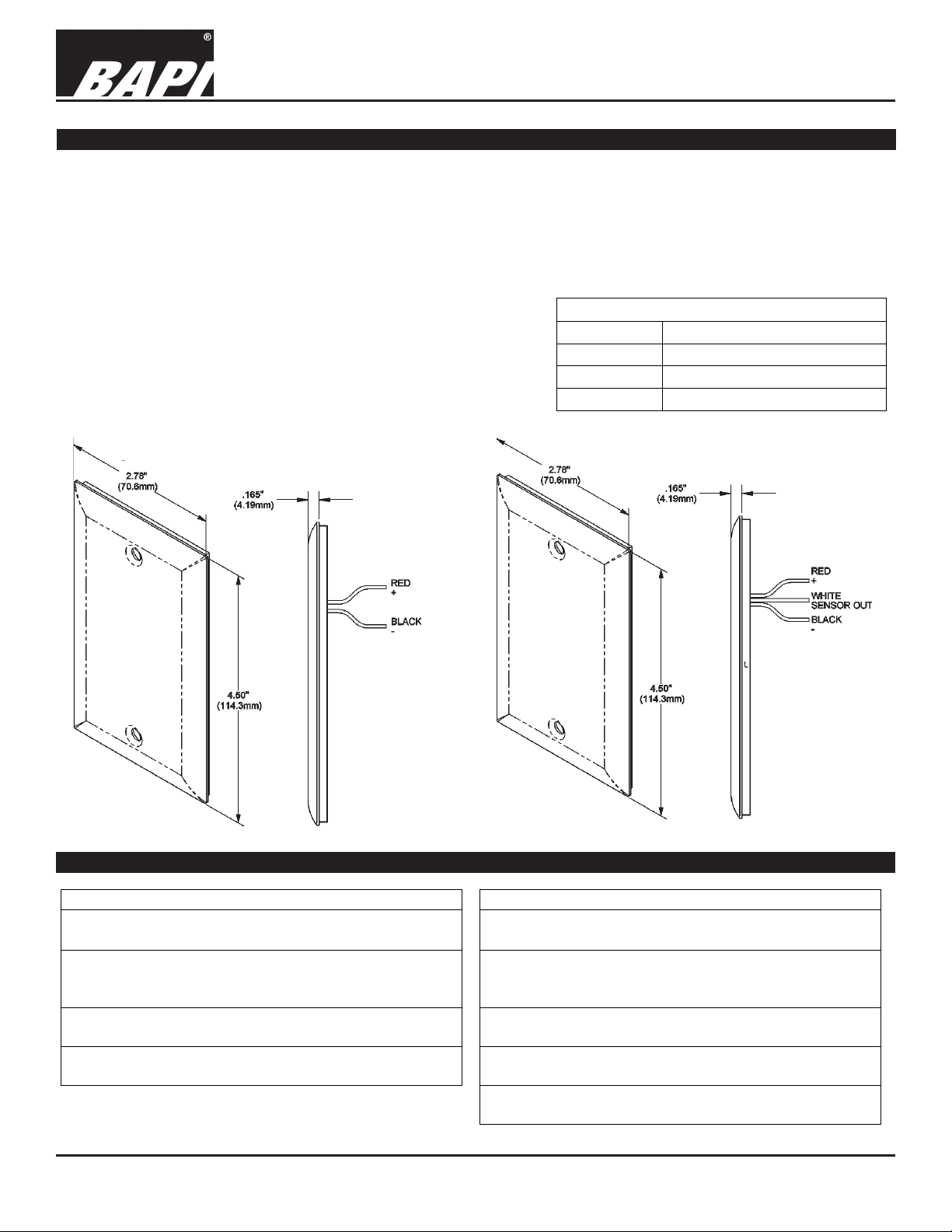
BAPI provides two styles of 592 sensor, one with and one without the
10K ohm, 0.1% resistor. The one with the resistor has three wires –
red, black and white. The one without the resistor has two wires – red
and black.
rev. 08/01/18
Fig. 1:
592 Semiconductor
2-wire unit
Termination
Specications subject to change without notice.
Fig. 2:
592 Semiconductor
3-wire unit
1 of 3
Page 2
Wallplate with Semiconductor Sensor (BA/592-SP/AP)
Installation & Operating Instructions
16558_ins_592_SP_AP
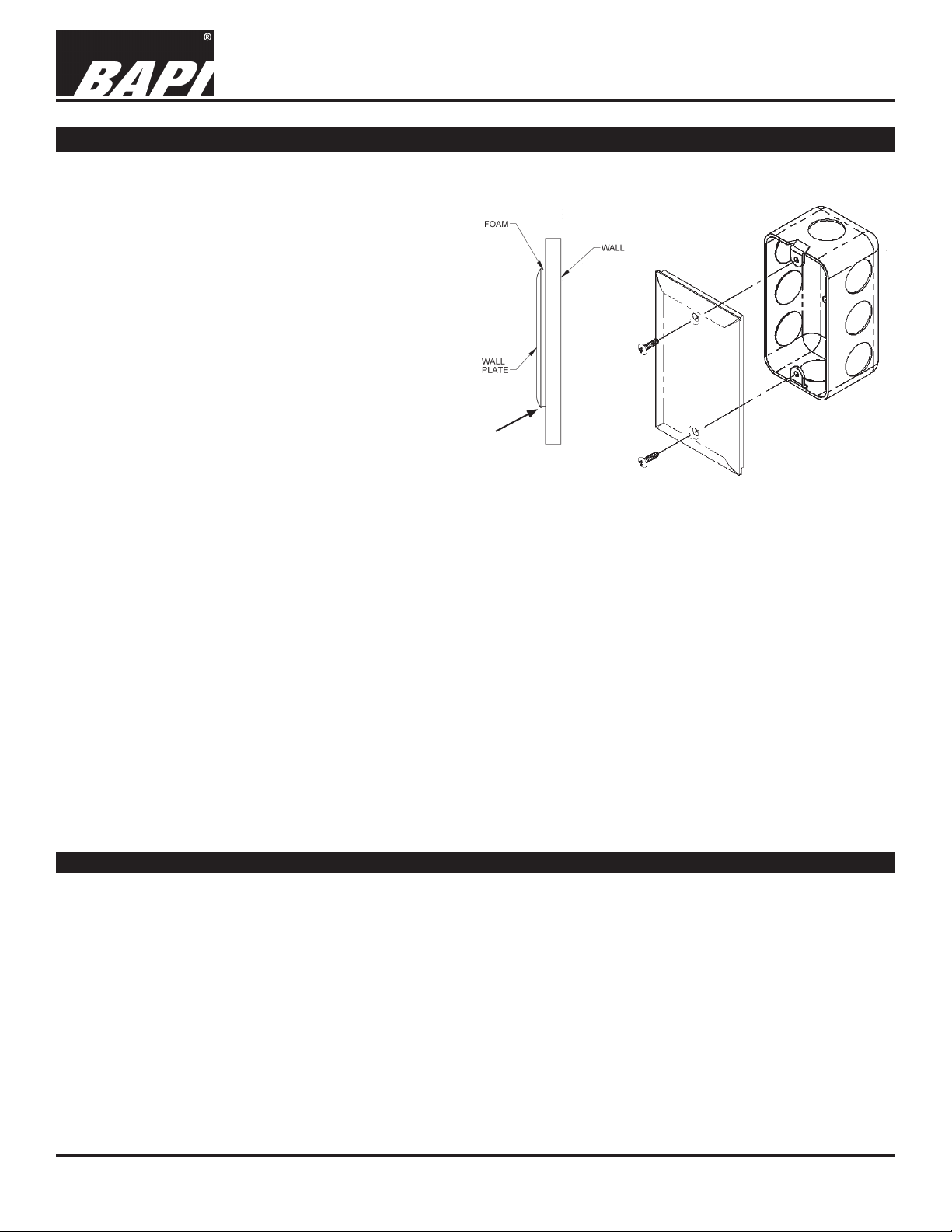
Mounting
Ensure the plate does not touch the wall when it is mounted as this will lead to slower response
rates when the environment changes.
Mounting hardware is provided for both
junction box and drywall installation.
Junction Box
1. Pull the wire through the wall and out of
the junction box, leaving about 6” free.
2. Terminate the unit according to the
guidelines in Termination on page 1.
3. Secure the plate to the box using the
#6-32 x 1/2” mounting screws provided
or with security screws which are
sold separately. (Call BAPI or visit the
Accessories section of our website for
security screw ordering.)
4. Tighten screws until the foam gasket on
the back plate is compressed about 50%.
Ensure the plate doesn’t touch the wall
(Fig 5).
Verify visible
air gap
between plate
and wall.
Fig 5:
Side View of
Mounted Plate
J-Box Mounting
rev. 08/01/18
Fig 6:
Note: Louvered wall plates require a mounting adapter bracket for J-Box mounting. The bracket is not shown in the
diagram above but is included with any louvered wall plates ordered from BAPI.
Drywall Mounting
1. Place the plate against the wall where you want to mount the sensor and mark out the two mounting holes.
2. Drill two 3/16” holes in the center of each marked mounting hole. Insert a drywall anchor into each hole.
3. Cut hole between the mounting holes that clears the apparatus mounted on plate. Pull the wire through the wall hole
cut in step 2, leaving about 6” free.
4. Terminate the unit according to the guidelines in Termination on page 1.
5. Secure the plate to the drywall anchors using the #6 x 1” mounting screws provided. Tighten screws until the foam
gasket on the back plate is compressed about 50%. Ensure the plate doesn’t touch the wall.
Note: In any wall-mount application, the wall temperature and the temperature of the air within the wall cavity can cause
erroneous readings. The mixing of room air and air from within the wall cavity can lead to condensation, erroneous
readings and premature failure of the sensor. To prevent these conditions, seal the conduit leading to the junction box or
ll the box with insulation.
Temperature Measurement Offsetting
All BA/592 sensors will have the following information provided on a label:
Therm Reading_______
The actual temperature reading according to
a thermometer that is certied traceable to
recognized standards by the National Institute of Standards and Technology (NIST).
Sensor Reading ______
The temperature reading according to
the AD592 sensor. The output is dropped
across a 10KΩ 0.1%, read in mV and
converted to a Fahrenheit temperature.
Offset_______
The difference between the
Thermometer Reading and
the Sensor Reading
To correct the Sensor Reading, simply add the offset value to the sensor reading so that it equals the thermometer reading.
e.g. Therm Reading = 74.6, Sensor Reading = 73.0, Offset = +1.6
Correction: Add (+1.6) °F to the sensor for an accurate reading: 73 + 1.6 = 74.6°F
e.g. Therm Reading = 75.4, Sensor Reading = 77.2, Offset = -1.8
Correction: Add (-1.6) °F to the sensor for an accurate reading: 77.2 + (-1.8) = 75.4°F
Specications subject to change without notice.
2 of 3
Page 3
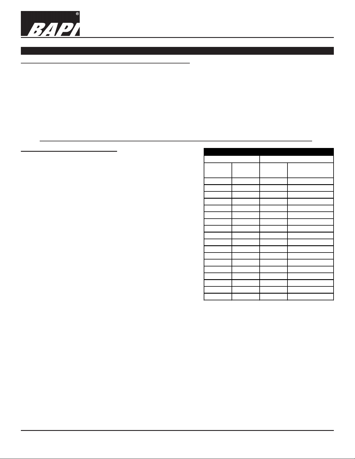
Wallplate with Semiconductor Sensor (BA/592-SP/AP)
°F °C
Output
Current uA
Output Voltage
across 10KΩ
50 10 283.2 2.832
60 15.56 288.8 2.888
62 16.67 289.9 2.899
64 17.78 291 2.91
66 18.89 292.1 2.921
68 20 293.2 2.932
70 21.11 294.3 2.943
72 22.22 295.4 2.954
74 23.33 296.5 2.965
76 24.44 297.6 2.976
78 25.56 298.8 2.988
80 26.67 299.9 2.999
82 27.78 301 3.01
84 28.89 302.1 3.021
86 30 303.2 3.032
88 31.11 304.3 3.043
90 32.22 305.4 3.054
100 37.78 311 3.11
Table 4: 592 Output
Temperature
592 Semiconductor
Installation & Operating Instructions
16558_ins_592_SP_AP
Diagnostics
GENERAL TROUBLESHOOTING AND POSSIBLE SOLUTIONS
- Determine that the input is set up correctly in the controller’s and building automation software.
- Check wiring for proper termination
- Check for corrosion at either the controller or the sensor. Clean off the corrosion, re-strip the interconnecting wire and
reapply the connection. In extreme cases, replace the controller, interconnecting wire and/or sensor.
- Label the terminals that the interconnecting wires are connected to at the sensor end and the controller end. Discon-
nect the interconnecting wires from the controller and the sensor. With the interconnecting wires separated at both ends
measure the resistance from wire-to-wire with a multimeter. The meter should read greater than 10 Meg-ohms, open
or OL depending on the meter you have. Short the interconnecting wires together at one end. Go to the other end and
measure the resistance from wire-to-wire with a multimeter. The meter should read less than 10 ohms (22 gauge or
larger, 250 feet or less). If either test fails, replace the wire.
592 SENSOR TROUBLESHOOTING
Note: The BAPI crimp-on sealant lled connectors have a
convenient hole opposite the wire opening to insert a meter probe
for measurements.
1) Measure the sensible temperature at the sensors location
using an accurate temperature standard.
2) Set your meter to the Volts setting.
3) Measure from the controller ground (black sensor lead) to the
592’s power lead (red sensor lead) for +5 to +30 VDC.
4) Set your meter to the mV setting.
a) For two wire units place a 10KΩ resistor between the
sensors black lead and the return wire to the controller.
Measure and record the voltage across the resistor.
b) For three-wire units measure and record the voltage from
the black lead to the white lead.
5) Using Table 4, if the sensor voltage is greater or less than
0.050VDC from the expected voltage measurement, call BAPI
technical support.
6) If the sensor reads properly, verify that the controller is
operating correctly.
7) If the sensor reads improperly, determine if the sensor is
exposed to an external source different from the measured
environment (conduit draft).
rev. 08/01/18
Specications subject to change without notice.
3 of 3
 Loading...