

Page 1
BA/10K-3(RZ)-RSOC Family
T ermination and Troubleshooting
14778_ins_(rz)rsoc
Termination
BAPI recommends using twisted pair of at least 22AWG and sealant filled connectors for all wire connections. Larger gauge
wire may be required for long runs. All wiring must comply with the National Electric Code (NEC) and local codes.
Do NOT run this device’s wiring in the same conduit as AC power wiring of NEC class 1, NEC class 2, NEC class 3 or with
wiring used to supply highly inductive loads such as motors, contactors and relays. BAPI’s tests show that fluctuating and
inaccurate signal levels are possible when AC power wiring is present in the same conduit as the signal lines. If you are
experiencing any of these difficulties, please contact your BAPI representative
BAPI does not recommend wiring the sensor with power applied as accidental arcing may
damage the product and will void the warranty
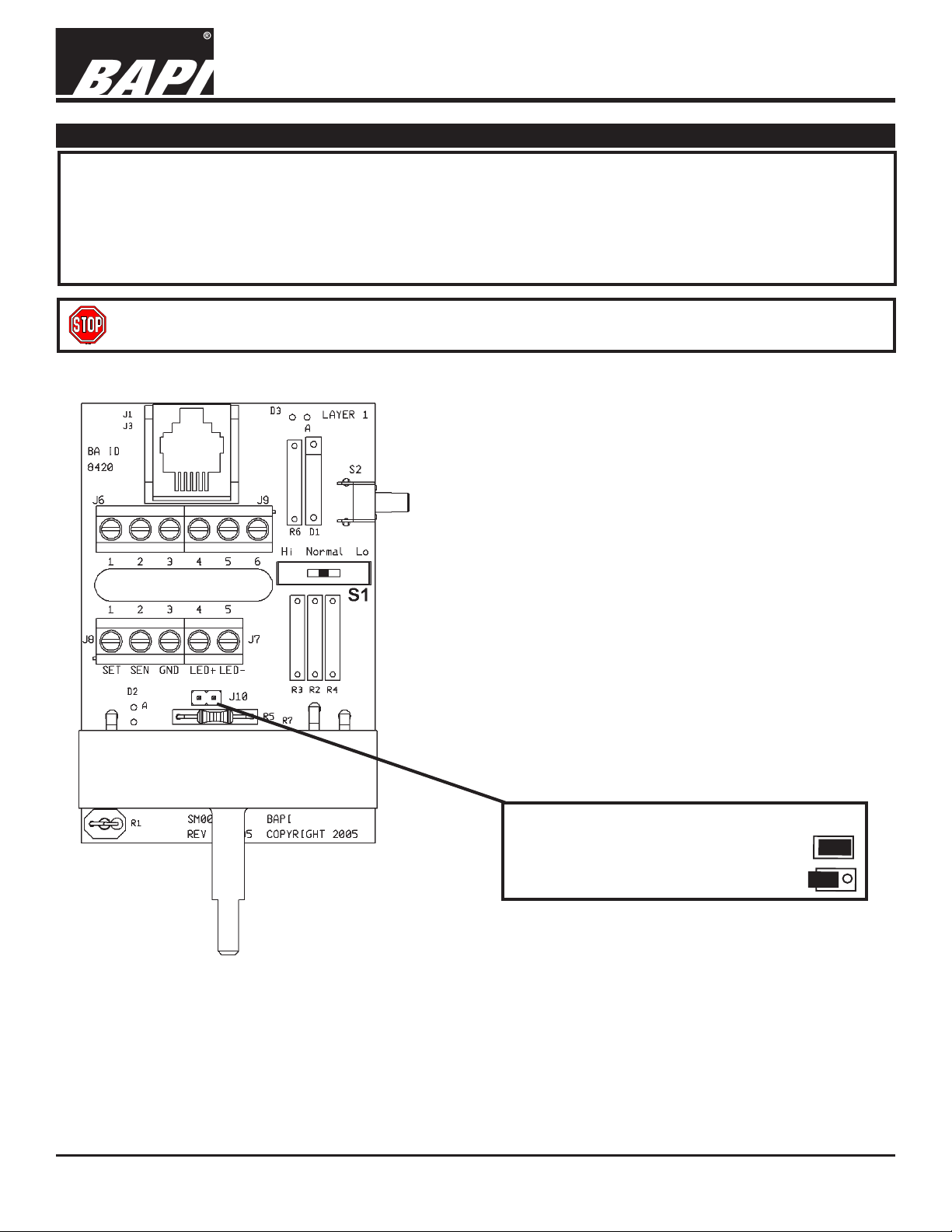
Wiring Connections
rev.
7/14/05
Fig. 1
SET [T o Analog Input of Controller]
[Range is 0 to 1K ohm or 10K to 11K ohm]
SEN [To Analog Input of Controller]
GND [To GND (common) of Controller]
LED+ [Hot/Positive]
[Occupancy LED activated with 24VAC or 5VDC]
LED- [Neutral/GND]
Jumper ‘J10’ - Setpoint
Setpoint Resistance = 0 to 1000 Ω
Setpoint Resistance = 10,000 to 1 1,000 Ω
Specifications subject to change without notice.
1
Page 2
14778_ins_(rz)rsoc
Termination continued...
BA/10K-3(RZ)-RSOC Family
T ermination and Troubleshooting
7/14/05
rev.
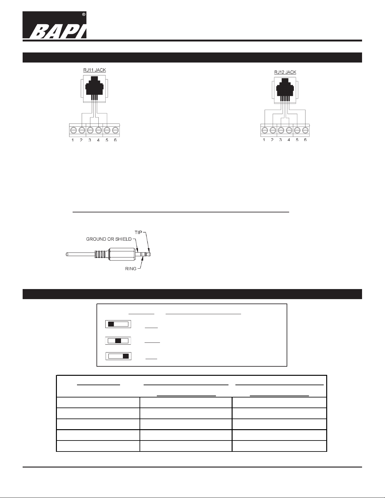
Fig. 2
C11 W iring
1 Not Connected
2 [Internally connected to Comm Jack pin 2]
3 [Internally connected to Comm Jack pin 3]
4 [Internally connected to Comm Jack pin 4]
5 [Internally connected to Comm Jack pin 5]
6 Not Connected
Fig. 4
Fig. 3
C12 Wiring
1 [Internally connected to Comm Jack pin 1]
2 [Internally connected to Comm Jack pin 2]
3 [Internally connected to Comm Jack pin 3]
4 [Internally connected to Comm Jack pin 4]
5 [Internally connected to Comm Jack pin 5]
6 [Internally connected to Comm Jack pin 6]
C35 Wiring
1 [Internally connected to Comm Jack GROUND]
2 [Internally connected to Comm Jack TIP]
3 [Internally connected to Comm Jack RING]
4 Not Connected
5 Not Connected
6 Not Connected
Optional Test & Balance Switch
Optional: Test and Balance Switch (S1)
High: Will set the sensor value HIGH temperature
Norm: Thermistor/RTD will operate normally
Low: Will set the sensor value LOW temperature
Senso r Type Low Temperature (40° F) High Temperature ( 105° F)
1000Ω RTD 1.02KΩ (41.2°F) 1.15KΩ (10 1.5 °F)
3000Ω Th er mistor 7.87KΩ (39.8°F) 1.5KΩ (106.8°F)
10K-2 Thermistor 30.1KΩ (34.9°F) 4.75KΩ (10 9.1 °F)
10K-3 Thermistor 26.7K
10K-3(11 K) Thermistor 7.32KΩ (43.7°F) 3.65KΩ (10 5.2 °F)
Specifications subject to change without notice.
Resistance Value Resistance Value
(35.9°F) 5.11KΩ (10 8.4 °F)
Ω
2
Page 3

14778_ins_(rz)rsoc
Troubleshooting
BA/10K-3(RZ)-RSOC Family
T ermination and Troubleshooting
7/14/05
rev.
Problems:
General troubleshooting
T emperature reading is incorrect
Possible Solutions:
- Determine that the input is set up correctly in the controller’s and
building automation software.
- Check wiring for proper termination
- Check for corrosion at either the controller or the sensor. Clean of f
the corrosion, re-strip the interconnecting wire and reapply the
connection. In extreme cases, replace the controller, interconnecting
wire and/or sensor.
- Label the terminals that the interconnecting wires are connected to
at the sensor end and the controller end. Disconnect the interconnecting wires from the controller and the sensor. With the interconnecting wires separated at both ends measure the resistance from
wire-to-wire with a multimeter. The meter should read greater than 10
Meg-ohms, open or OL depending on the meter you have. Short the
interconnecting wires together at one end. Go to the other end and
measure the resistance from wire-to-wire with a multimeter . The
meter should read less than 10 ohms (22 gauge or larger, 250 feet or
less). If either test fails, replace the wire.
- Determine that the temperature sensors wires are connected to the
correct controller input terminals and are not loose.
- Check the wires at the sensor for proper connections.
- Measure the physical temperature at the temperature sensor’s
location using an accurate temperature standard. Disconnect the
temperature sensor wires and measure the temperature sensor’s
resistance across the sensor output pins with an ohmmeter . Compare the temperature sensor’s resistance to the appropriate temperature sensor table on the BAPI web site. If the measured resistance is
different from the temperature table by more than 5% call BAPI
technical support. Find BAPI’s web site at www .bapihvac.com; click
on the button labeled SENSORS on the left of the screen and then
click on the type of sensor you have. Don’t forget to reconnect the
wires.
- Make sure that the test and balance switch is in the correct position.
- Make sure that the sensor leads are not touching
Setpoint reading is incorrect
Override is not working correctly
- Make sure that the setpoint output is correct. Remove the setpoint
output wire and check the output for the correct resistance or voltage
output. See the product label for your specific range. Don’t forget to
reconnect the wire.
- Check that the resistance across the override output is less than 5
ohms when the override switch is pushed
- Make sure that the override jumper setting are correct.
Specifications subject to change without notice.
3
Page 4

14778_ins_(rz)rsoc
Mounting
Fig. 5
BA/10K-3(RZ)-RSOC Family
T ermination and Troubleshooting
7/14/05
rev.
Mounting hardware is provided for both junction box and drywall installation (junction box installation shown).
Junction Box
1. Pull the wire through the wall and out of the junction box, leaving about six inches free.
2. Pull the wire through the hole in the base plate.
3. Secure the plate to the box using the #6-32 x 1/2 inch mounting screw provided.
4. Terminate the unit according to the guidelines in Termination on p age 1.
5. Attach Cover by latching it to the top of the base, rotating the cover down and snapping it into place.
6. Secure the cover by backing out the lock-down screws using a 1/16" allen wrench until they are flush with the bottom of
the cover.
Drywall Mounting
1. Place the base plate against the wall where you want to mount the sensor.
2. Using a pencil mark out the two mounting holes and the area where the wires will come through the wall.
3. Drill two 3/16" holes in the center of each marked mounting hole. Insert a drywall anchor into each hole.
4. Drill one 1/2" hole in the middle of the marked wiring area.
5. Pull the wire through the wall and out of the 1/2" hole, leaving about six inches free.
6. Pull the wire through the hole in the base plate.
7. Secure the base to the drywall anchors using the #6 x 1 inch mounting screws provided.
8. Terminate the unit according to the guidelines in Termination on p age 1.
9. Attach cover by latching it to the top of the base, rotating the cover down and snapping it into place.
10. Secure the cover by backing out the lock-down screws using a 1/16" allen wrench until they are flush with the bottom of
the cover.
NOTE
In a wall-mount application, the wall temperature and the temperature of the air within the wall cavity can cause erroneous
readings. The mixing of room air and air from within the wall cavity can lead to condensation, erroneous readings and
premature failure of the sensor. To prevent these conditions, seal the conduit leading to the junction box and use BAPI’s
adhesive backed, foam insulating pad centered over the hole (order part number BA/FOAMBACK).
Specifications subject to change without notice.
4
 Loading...