

Page 1
Duct & Outside Air Humidity Units with RTD Temperature Transmitter
Humidity Output (4 to 20mA, 0 to 5V, 0/2 to 10V), Temperature Output (4 to 20mA)
Installation and Operating Instructions
26415_ins_hum_RTD_temp_trans_duct_out
Overview
The BA/T1x-(H2xx, H3xx) is a humidity transmitter which comes in 2% or 3% accuracies and an RTD temperature
transmitter. It can be ordered for either Duct or Outside Air applications with a doublegang Weatherproof Enclosure
(NEMA 3R) or a BAPI-Box Enclosure (NEMA 4, IP66). The humidity transmitter can be ordered with 4 to 20 mA, 0 to
5VDC, 0 to 10V or 2 to 10V output while the temperature transmitter has a 4 to 20mA output.
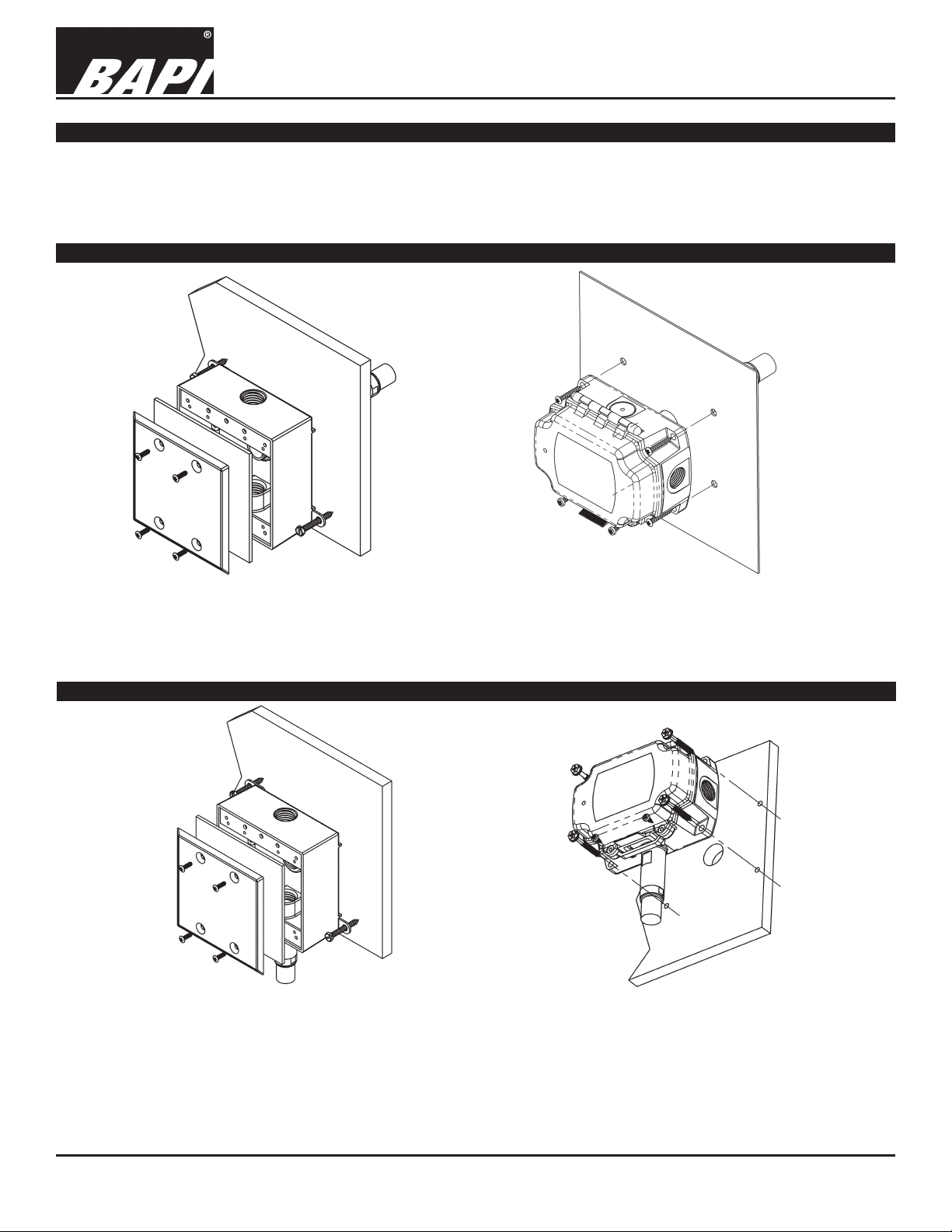
Duct Unit Mounting
rev. 01/12/16
Fig. 1: Duct Humidity Unit in a Weatherproof (WP) Enclosure
Fig. 2: Duct Humidity Unit in a BAPI-Box (BB) Enclosure
Mount in the center of the duct wall at least 3 duct diameters from humidiers. Drill a 1 inch hole in the duct for the probe
and use two number 8 sheet metal screws to attach the sensor to the duct. Center the probe in its mounting hole. Be sure
that the foam seals the hole, but do not over tighten the screws.
Outside Air Mounting
Fig. 3: Outside Air Humidity in a Weatherproof (WP) Enclosure
Fig. 4: Outside Humidity Unit in a BAPI-Box (BB) Enclosure
Mount in a permanently shaded area away from windows and doors. Do not mount in direct sunlight. Mount with the
sensor probe pointed down. Drill a hole large enough for your sensor cable through your mounting surface. Mount the
unit to the surface with the wiring knock-out centered over the wiring hole. Pull the wiring into the unit and terminate using
sealant lled connectors. Best practice is to seal the wiring hole with caulk after the wiring is installed. Be sure that the
foam on the back of the unit makes a good weather tight seal.
Specications subject to change without notice.
1 of 4
Page 2
26415_ins_hum_RTD_temp_trans_duct_out
Table 1: Humidty Transmitter with 4 to 20mA Output
Table 2: HumidityTransmitter with 0 to 5VDC Output
Red
Termination
Duct & Outside Air Humidity Units with RTD Temperature Transmitter
Humidity Output (4 to 20mA, 0 to 5V, 0/2 to 10V), Temperature Output (4 to 20mA)
Installation and Operating Instructions
rev. 01/12/16
Wire Color Purpose Note
White Not Used Not Used (Cap Wires)
Black Humidity Output 4 to 20 mA, To Analog Input of Controller
Red Power 10 to 35VDC
Wire Color Purpose Note
White Humidity Output 0 to 5VDC, To Analog Input of Controller
Black GND (Common) Ground for Power and Humidity Output
Power 10 to 35VDC or 12 to 27 VAC
Table 3: Humidity Transmitter with 0 to 10VDC Output
Wire Color Purpose Note
Green Humidity Output 0 to 10VDC, To Analog Input of Controller
Black GND (Common) Ground for Power and Humidity Output
Red Power 15 to 35VDC or 15 to 27VAC
Table 4: Humidity Transmitter with 2 to 10VDC Output
Wire Color Purpose Note
Brown Humidity Output 2 to 10VDC, To Analog Input of Controller
Black GND (Common) Ground for Power and Humidity Output
Red Power 15 to 35VDC or 15 to 27VAC
Table 5: Temperature Transmitter with 4 to 20mA Output
Wire Color Purpose Note
Black Temperature Output 4 to 20mA, To Analog Input of Controller
Red Power 7 to 40VDC
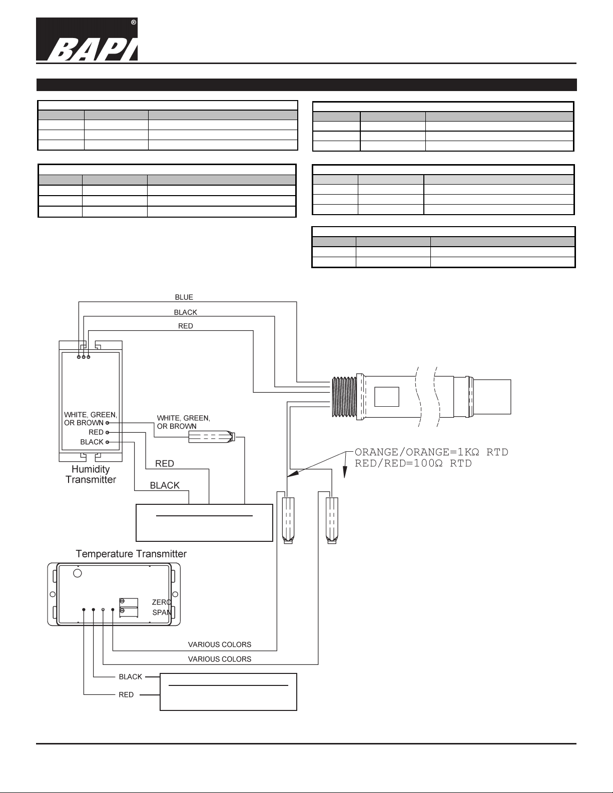
Humidity Output & Power
See Tables 1 through 4 above for
Wiring Information
Temperature Output and Power
See Table 5 above for Wiring
Fig. 5: Wiring Diagram
Notes:
2% and 3% Humidity Transmitters Are Polarity
Sensitive as well as Reverse Polarity Protected.
Information
Specications subject to change without notice.
2 of 4
Page 3

Duct & Outside Air Humidity Units with RTD Temperature Transmitter
Humidity Output (4 to 20mA, 0 to 5V, 0/2 to 10V), Temperature Output (4 to 20mA)
Installation and Operating Instructions
26415_ins_hum_RTD_temp_trans_duct_out
Specications
Power:
Units with RH Output of 4 to 20mA or 0 to 5VDC: 10 to 35VDC, 22mA max
Units with RH Output of 0 to 5VDC: 12 to 27VAC, 0.53VA max
Units with RH Output of 0 to 10VDC or 2 to 10VDC: 15 to 35VDC, 6mA max or 15 to 27VAC, 0.14VA max
Units with Temperature Output of 4 to 20mA: 7 to 40VDC, 22mA max
Humidity Sensor: Factory corrected @17 RH points (10 to 90% RH)
Humidity Capacitive Polymer
RH Accuracy ±2% @ 73°F (23°C) from 10 to 90%
Drift 0.5% per year
Response time < 5 seconds in moving air
RH Linearity Negligible, factory corrected linier from 10 to 90%
RH Hysteresis Factory corrected to <1%
Humidity Filter: 80 micron sintered stainless steel lter
Humidity Transmitter Output
Transmitter Output 0 to 100%
H200, H300 4 to 20mA output, 700Ω@24VDC, Voltage drop is 10VDC
H200, H300 0 to 5VDC output, 10kΩ
H210, H310 0 to 10VDC output, 10kΩ
H212, H312 2 to 10VDC output, 10kΩ
Humidity Sensor Calibrated Accuracy: Calibration @17 RH points, (10% to 90%)
RH 2%
RH 3%
Output Wiring 2 wire current loop, or 3 wire voltage
Transmitter Ambient
Temperature -4 to 158ºF (-20 to 70ºC)
Humidity 0 to 100% RH, condensing
Probe Ambient:
Temperature -40º to 158ºF, (-40º to 70ºC)
Humidity 0 to 100% RH, condensing
Probe Length:
Duct 5.3” (13.5cm) Duct Insertion, 1” dia.
Outside Air 2.4” (6.1cm) Below Enclosure, 1” dia.
Dimensions: W x H x D
Weatherproof (
(doublegang)
BAPI-Box (BB)
Enclosure Material:
Weatherproof (WP)
BAPI-Box (BB) Polycarbonate, UV resistant
Enclosures Ratings:
Weatherproof (WP)
BAPI-Box (BB) NEMA-4, IP66, UL94V-0
Termination: Open wire
Crimp 18 to 26 AWG with Sealant Filled Crimp Connector (BA/SFC1000-x00)
Wire Nut 26 to 16 AWG with Sealant Filled Wire Nut (BA/SFC2000-x00)
Approvals: RoHs
2% from 10 to 90% @ 73°F (23°C), Non-condensing
3% from 10 to 95% @ 73°F (23°C), Non-condensing
WP) 4.5” x 4.5” x 2.2”, (114 x 114 x 55 mm)
4.15” x 5” x 2.5”, (105.4 x 127 x 63.5mm)
Cast Aluminum (doublegang)
NEMA-3R (doublegang)
Temperature Sensor:
T1K Platinum 1KΩ RTD
T100 Platinum 100Ω RTD (discontinued)
RTD Transmitter Output
Transmitter Output 4 to 20mA, 850Ω@24VDC
Output Wiring 2 wire loop
Output Limits <1mA (short), <22.35mA (open)
Span Min. 30ºF (17ºC), Max 1000ºF, (555ºC)
Zero Min. Min -130°F (-90°C)
Zero Max Max 900ºF (482ºC)
Accuracy ±0.065% of span
Linearity ±0.125% of span
Power Output Shift ±0.009% of span
RTD Sensor 2 wire Platinum (Pt), 385 curve
Transmitter Ambient -4 to 158ºF (-20 to 70ºC)
0 to 100% RH, condensing
rev. 01/12/16
Specications subject to change without notice.
3 of 4
Page 4

Duct & Outside Air Humidity Units with RTD Temperature Transmitter
Humidity Output (4 to 20mA, 0 to 5V, 0/2 to 10V), Temperature Output (4 to 20mA)
Installation and Operating Instructions
26415_ins_hum_RTD_temp_trans_duct_out
Filter Care
A lter protects the humidity sensor from various airborne particles that might reduce the sensor’s accuracy. Depending
on the sensor’s location and environment, this lter may need periodic cleaning. To do this, gently unscrew the lter from
the probe. Rinse the lter under warm water until clean. Warm soapy water may be used if necessary. Gently replace the
lter by screwing it back into the probe. The lter should screw all the way into the probe. Hand tighten only. If a replacement lter or replacement probe is needed, call BAPI.
BA/HDOFS3 Stainless Steel Sintered Filter Replacement
Diagnostics - Humidity
rev. 01/12/16
Possible Problems:
Unit will not operate
Humidity output is at its maximum
or minumum value
Humidity reading in controller’s
software appears to be off by
more than the specied accuracy
Output Humidity Formula
4 to 20mA %RH =(mA-4)/0.16
0 to 5VDC %RH = V/0.05
0 to 10VDC %RH = V/0.1
2 to 10VDC %RH = (V-2)/0.08
Diagnostics - Temperature
Possible Problems:
Unit will not operate
Temperature sensor reading
is inaccurate at the controller
software
Temperature Equation
(A-4)x(Tspan)
low +
T = T
T = Temperature at sensor
Tlow = Low temperature of span
Thigh = High temperature of span
Tspan = Thigh - Tlow
A = Ammeter reading in mA
Note:
The temperature surrounding
the transmitter must be between
-4 and 158
16
o
F (-20 and 70oC).
Possible Solutions:
- Check for proper supply power. (See the wiring diagram and power specications)
- Make sure the humidity sensor is wired properly.
- Check all software parameters
- Determine if the sensor is exposed to an external air source different from the
measured environment, such as air inltration through the wiring conduit.
- Check the Humidity transmitter output against a calibrated reference such as a
2% accurate hygrometer. Measure the humidity at the sensor’s location using the
reference meter, then calculate the humidity transmitter output using the humidity
formula at left. Compare the calculated output to the actual humidity transmitter
output (see the wiring diagram for the humidity transmitter output wire colors). If
the calculated output differs from the humidity transmitter output by more than 5%,
contact BAPI technical support.
Possible Solutions:
- Check for proper supply power (7 to 40VDC) to the temperature transmitter. (See
pages 2 for wiring diagram and power specications.)
- Determine if the input is set up correctly in the controller’s front end software.
- Check if the RTD sensor wires are physically open or shorted.
- Determine if the sensor is exposed to an external air source different from the
measured environment, such as air inltration through the wiring conduit.
- Check the resistance of the temperature sensor (located inside the unit’s probe)
against an accurate temperature standard. Measure the temperature at the
sensor’s location using a reference meter. Disconnect the temperature sensor
wires (2 Red Wires for a 100 Ohm Platinum RTD sensor or 2 Orange Wires for
a 1,000 Ohm Platinum RTD sensor) and measure the temperature sensor’s
resistance with an ohmmeter. Compare this resistance to the appropriate
temperature sensor’s Output Table on the BAPI website. (Go to www.bapihvac.
com; click on “Resource Library” and “Sensor Specs” and then on the 100 Ohm
Plat. RTD or the 1,000 Ohm Plat. RTD.) If the measured resistance is different
from the Output Table by more than 5%, contact BAPI technical support.
- Check the output current of the temperature transmitter (located inside the unit’s
enclosure) against an accurate temperature standard. Measure the temperature
at the sensor’s location using a reference meter. Measure the transmitter current
by placing an ammeter in series with the controller input (the black wire on the
temperature transmitter). The current should read according to the equation at left.
If the measured output is different from the calculated output, call BAPI technical
support. If the measured output is the same as the calculated output, then check
the wiring between the unit and the controller.
Specications subject to change without notice.
4 of 4
 Loading...